UD Trucks. Owner’s Manual (2011-2013) - page 6


  Главная      Manuals     UD Trucks. Owner’s Manual (VEHICLE SERVICE AND MAINTENANCE) (2011-2013)


Search            copyright infringement  


Content      ..     4      5      6      7     ..


UD Trucks. Owner’s Manual (2011-2013) - page 6


-------------------------------------------------------------------------------------------------------------------------------------------------------------
INSTRUMENTS AND CONTROLS
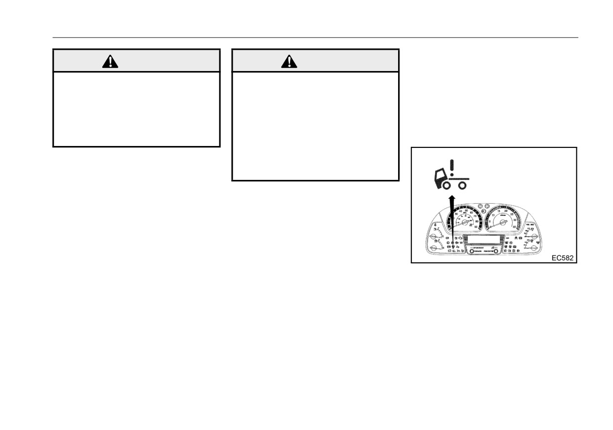
Tilt lock warning light
WARNING
WARNING
If the tilt lock of the cab is improperly
z Never operate the vehicle with
z
Never drive the vehicle while
latched, the warning light will come
the warning light on and a
the warning light is on and the
on and the warning buzzer will
warning buzzer sounding. The
warning buzzer is sounding.
sound.
brakes may provide less effec-
The brakes will not provide
When the tilt lock is secure, the
tive action or become totally
normal braking effectiveness
warning light will go off and the warn-
ineffective.
and may become totally inef-
ing buzzer will stop sounding.
fective. Determine cause of
<Brake fluid level (Not applicable to
brake fluid loss, repair system,
UD3300)>
and refill brake fluid.
When the fluid level in the brake fluid
reservoir drops below the normal
operating level, the warning light
comes on and a warning buzzer
sounds. The buzzer stops when the
vehicle is stopped and the parking
brake is engaged.
Have the brake system checked and
repaired by an authorized UD Trucks
dealer or a qualified brake service
When the warning light comes on
facility.
and the warning buzzer sounds,
immediately move the vehicle to a
safe place. To do this, apply the
brake slowly.
Correct the tilt lock of the cab, and
make sure that the cab is securely
locked and the warning light is off. If
the warning light does not turn off,
have the tilt lock system checked at
7 - 48

-------------------------------------------------------------------------------------------------------------------------------------------------------------

INSTRUMENTS AND CONTROLS
an authorized UD Trucks dealer or
ATM shift limit warning light
CAUTION
other qualified service facility.
(Allison 1000, 2200 and 2500
series)
z Do not drive the vehicle if the
warning light remains on. Have
WARNING
The warning light comes on when
the vehicle checked by an
there has been an error in operation
authorized UD Trucks dealer
z
Do not operate the vehicle
or when the safety circuit has been
when the warning light is on
activated. It indicates that the
and the warning buzzer is
Shift limit
change from the current range to
sounding. Otherwise, if the
Under the following conditions, the
another specified range cannot be
brake is used during driving,
transmission control module (TCM)
done.
the cab could raise, causing a
prohibits gear shifting for the pur-
For Allison 3000 series, refer to the
serious accident.
pose of transmission protection, as
"SHIFT LIMIT warning message" on
the reaction of diagnostic trouble
page 10-30.
code (DTC) or a safety measure of
optional functions.
1.Idling too high: At
1,000 rpm or
higher, shifting from the Neutral is
prohibited.
2.Forward/reverse
change-over:
When the vehicle is moving at over
a specified speed, forward/reverse
change-over is prohibited. If this
occurs, stop the vehicle, and shift
first to P or N. then depress the
brake pedal and shift to the
desired driving range.
3.Transmission failure: When the
TCM receives abnormal signals,
gear shifting is limited to protect
7 - 49

-------------------------------------------------------------------------------------------------------------------------------------------------------------

INSTRUMENTS AND CONTROLS
the system from major troubles.
Exhaust gas high temperature
ATM maintenance information
The SHIFT LIMIT warning light
indicator light
light
and the ATM SYSTEM warning
This indicator does not indicate a
This light will illuminate when the
light illuminate and transmission is
system malfunction, however it
ATM should be serviced as soon as
fixed to a safety range. When the
alerts the driver of the high tempera-
possible for its components such as
lock up clutch is engaged, it will be
ture of the system.
fluid, filter or clutch.
disengaged.
For details, refer to the section
DANGER
"Automatic transmission mainte-
nance schedule" on page 11-12.
z Exhaust
component and
exhaust gas are at extremely
high temperature when this
CAUTION
warning light becomes on.
z Do not continue driving the
z When parking vehicle keep
vehicle with the ATM mainte-
away from people, or any flam-
nance information light on.
mable materials, vapors or
Doing so may cause damage
structures.
to the ATM.
7 - 50

-------------------------------------------------------------------------------------------------------------------------------------------------------------

INSTRUMENTS AND CONTROLS
Turn signal and hazard indicator
Exhaust brake indicator light
Intake air heater indicator light
light
The indicator light will come on if the
The indicator light will come on when
exhaust brake switch is turned on
When the turn signal switch is oper-
the ignition key is turned to the ON
and the exhaust brake is operating.
ated, the left or right indicator light
position to preheat intake air. When
flashes. When the hazard warning
the light goes off, the engine is ready
flasher switch is turned to the ON
to start.
position, the left and right indicator
lights flash simultaneously.
NOTE:
z Do not crank the engine until the
indicator light goes off.
The intake air heater will not activate
unless the engine coolant tempera-
ture drops below normal operating
temperature.
The engine coolant temperature
determines whether the indicator
light stays off or comes on when the
ignition key is turned to the ON posi-
tion.
7 - 51

-------------------------------------------------------------------------------------------------------------------------------------------------------------

INSTRUMENTS AND CONTROLS
High beam indicator light
Automatic transmission O/D OFF
POWER MODE indicator light
indicator light (Allison 1000, 2200
This indicator light comes on when
The indicator light will come on when
and 2500 series)
the dimmer switch is set to the high
the power mode switch is set to the
beam position with the lighting
This indicator comes on when the
power mode.
switch in the second position or the
overdrive switch is turned OFF. The
passing switch is operated.
overdrive switch is located on the
While operating, the indicator light in
selector lever.
the switch come on. (Allison 1000,
2200, 2500 series)
Allison 1000, 2200, 2500 series
While operating, both the indicator
light in the power mode switch and
the indicator light on the multi-dis-
play monitor come on. (Allison 3000
series)
7 - 52

-------------------------------------------------------------------------------------------------------------------------------------------------------------

INSTRUMENTS AND CONTROLS
SWITCHES AND BUTTONS
Engine throttle control knob
Allison 3000 series
The automatic adjustment of engine
idling speed
z When the knob is turned all the
way to the left (counterclockwise),
The engine throttle control knob,
automatic idling mode will be
located to the left of the steering col-
reached, and the engine idling
umn, can be used to adjust engine
speed will be adjusted automati-
idling speed. Normal engine idling
cally according to the temperature
speed is 550 rpm. If equipped with
of the engine coolant.
automatic transmission, make sure
z Normally, this should be turned all
the engine idling speed is 550 rpm at
the way to the left (counterclock-
the forward range.
Allison 3000 series
wise).
7 - 53

-------------------------------------------------------------------------------------------------------------------------------------------------------------

INSTRUMENTS AND CONTROLS
Engine warm-up switch
CAUTION
z
The engine warm-up system oper-
z
The manual adjustment mode
ates the exhaust shutter during
is canceled while driving. Set
idling to shorten the engine warm-
to the automatic adjustment
up time and temperature of the
mode while driving.
engine coolant.
z
Turn the knob carefully, or the
Note that the engine warm-up sys-
engine speed may increase too
tem can only be used when the
quickly.
vehicle is stopped.
z
For information regarding the oper-
The manual adjustment of engine
ation method, refer to the section
idling speed
“To quickly warm up the engine” of
z Stop the vehicle and apply the
Vehicle Operation.
parking brake before performing
manual adjustment.
z When the knob is turned to the
right
(clockwise), the mode
changes from automatic idling
mode to manual adjustment mode,
the engine speed will increase,
and adjustment up to about 980
rpm will become possible.
7 - 54

-------------------------------------------------------------------------------------------------------------------------------------------------------------

INSTRUMENTS AND CONTROLS
engine speed is increased, or
Windshield wiper, washer and
WARNING
the clutch pedal is depressed.
exhaust brake switch
z
If the engine coolant tempera-
z
Do not warm up the engine in
ture rises abnormally when the
Windshield wiper and washer
areas with poor ventilation.
engine warm-up switch is ON,
the engine warm-up system will
automatically cancel it.
CAUTION
z
When not warming up the
engine, leave the engine warm-
up switch OFF. Leaving it on
could worsen the fuel econ-
omy when idling.
z
Leave the engine warm-up
switch OFF when the transmis-
sion PTO is operating.
The windshield wiper control
is
z
When turning ON the engine
located on the lever mounted on the
warm-up switch, put the throt-
right side of the steering column.
tle control knob in the AUTO
position. Turning the engine
z Turning this switch turns on the
warm-up switch to ON when at
wipers, and washer liquid is
high speed could generate
sprayed while pushing the switch
black smoke, although this
on the end of the lever.
only occurs rarely.
INT: Intermittent operation
NOTE:
LO: Operates at a low speed
z Even if the engine warm-up
HI: Operates at a high speed
switch is ON, the engine warm-
up system will cancel it if the
vehicle is being driven, the
7 - 55

-------------------------------------------------------------------------------------------------------------------------------------------------------------

INSTRUMENTS AND CONTROLS
z Operating the wipers when the
Exhaust brake
CAUTION
wiper blades are stuck or frozen to
the glass will cause the wiper stop
z
Do not operate the windshield
function to operate and temporarily
wipers when the windshield is
dry. Dry wiper operation will
stop the wipers (for about 10 sec-
scratch the windshield.
onds). When this happens, be sure
z
To avoid damage to the washer
to turn off the wiper switch and
motor, do not operate the
remove what is causing the wiper
windshield washer continu-
blades to stick before operating
ously for more than 20 sec-
the wipers again.
onds or with no washer fluid in
the tank.
z
To avoid damage to the wiper
WARNING
blades, do not operate the wip-
Operating instructions for exhaust
ers when the windshield is
brake
z
Do not use cooling system
iced over.
Exhaust brake provides additional
solution in the windshield
z
The windshield wiper motor is
engine braking effect. Use it as an
washer fluid reservoir. When
protected by a circuit breaker
auxiliary brake when descending a
sprayed on the windshield,
in addition to a fuse. If the
prolonged grade or when decelerat-
cooling system solution can
motor overheats, due to over-
ing from high speeds. The exhaust
significantly affect visibility.
load caused by heavy snow,
brake is controlled by the exhaust
z
To reduce the possibility of
etc., the wiper will remain
brake switch lever located on the
washer fluid freezing on the
stopped until the motor cools.
right side of the steering column.
windshield which may reduce
Be sure to have the cause of
visibility, use the defroster to
To apply the exhaust brake, move
the overload corrected.
warm the windshield.
the lever upward to the ON position
with the accelerator and clutch ped-
als released and shift gear in other
than neutral. An indicator light on the
instrument panel comes on when the
7 - 56

-------------------------------------------------------------------------------------------------------------------------------------------------------------

INSTRUMENTS AND CONTROLS
lever is in the ON position and the
If the exhaust brake is released by
Lighting, dimmer, passing and
exhaust brake is operating.
depressing the accelerator pedal
turn signal switch
The exhaust brake is activated only
suddenly and not by operating the
This switch lever mounted on the left
when both clutch and accelerator
lever, it may cause fuel injection into
side of the steering column operates
pedals are released. The purpose of
the engine with a blocked exhaust
and dims the headlights. It also
these provisions is to protect the
system and subsequent puff of black
serves as a turn signal and passing
engine and to improve driveability.
smoke and possible exhaust pipe
switch.
overheating.
To release the exhaust brake, move
the lever downward to the OFF posi-
Lighting
While the vehicle is stationed, con-
tion. Depressing either the accelera-
firm exhaust brake actuation by fol-
tor or clutch pedal can release the
lowing procedures:
exhaust brake, but it is preferable to
use the lever to release the exhaust
1.Move the exhaust brake switch
brake.
lever upward to the ON position
NOTE:
2.Confirm that the exhaust brake
z The wheels could slip when
indicator light illuminates and
using the exhaust brake while
that the engine sound changes
driving on slippery roads or
at the same time.
over bumps, etc., which could
cause the ABS to operate and
the exhaust brake to be tempo-
Turn the
knob
on
the
end
of
the
rarily cancelled and the indica-
switch lever to the 1st or 2nd position
tor light to turn off, but this is
to operate the following lights.
normal ABS operation and is
not a problem. Try to drive care-
fully taking into consideration
the road conditions, the inter-
vehicular distance, and other
factors.
7 - 57

-------------------------------------------------------------------------------------------------------------------------------------------------------------

INSTRUMENTS AND CONTROLS
Knob
* The daytime running lights comes
Dimmer, passing and turn signal
Light name
position
on when:
1st
2nd
z The ignition key is turned ON.
z The headlight is turned off
(with
Tail light
the lighting switch in the OFF or
1st position).
License plate light
z The parking brake is released.
(After the headlight comes on, it
will not turn off when operating the
Front position light
parking brake.)
Instrument cluster illumi-
NOTE:
nation light
z If the lighting switch is in the 1st
position, daytime running light
Heater or Air conditioner
To operate the left turn signal, pull
control illumination light
does not go out by turning off
the turn lever on the left side of the
the key switch. The light goes
steering column down beyond the
Automatic transmission
out when the lighting switch is
selector control illumina-
resistance. To operate the right turn
tion light
turned off.
signal, push the lever up beyond the
resistance. The lever will automati-
Clearance and identifica-
tion light
cally return to the neutral position
after the turn is completed. When
operating the left or right signal, con-
Headlight
firm that the TURN SIGNAL AND
HAZARD indicator light flashes.
*Daytime running light
When the ON-OFF intervals are
unusually short, the bulb is probably
burned out.
7 - 58

-------------------------------------------------------------------------------------------------------------------------------------------------------------

INSTRUMENTS AND CONTROLS
Hazard warning flasher switch
Cruise Control
WARNING
Cruise Control is a device that allows
z Replace the burned-out bulb
a vehicle to be driven at a set con-
as soon as possible.
stant speed without depressing the
accelerator pedal with your foot. This
To change the headlights to high
is useful when driving on express-
beam, push the turn lever forward.
ways and at other times when there
To return the headlights to low beam
is no need to accelerate or brake fre-
pull the lever to its normal position.
quently. Cruise Control is engaged
An indicator light on the instrument
by switching it on at the speed you
panel comes on when the headlights
want to maintain.
are on high beam.
The hazard warning flasher switch is
The headlight high beams can be
located on the lever mounted on the
momentarily operated as a signal
right side of the steering column.
when passing another vehicle by
Use the switch to warn approaching
pulling the turn lever towards the
vehicles during an emergency stop or
driver. The lever will return to the
other extraordinary conditions. Pull the
neutral position when released.
switch lever to activate the hazard
Return the headlights to the low
warning flashers. When the switch is
beam position as a courtesy when
operated, both the outside left and
overtaking vehicles or meeting
right turn signals and TURN SIGNAL
oncoming traffic.
AND HAZARD indicator lights flash.
Pull the switch lever to turn off the
flashers. The switch can be used with
the ignition key in any position.
NOTE:
z Turn flasher signals do not work
when the switch is operating.
7 - 59

-------------------------------------------------------------------------------------------------------------------------------------------------------------

INSTRUMENTS AND CONTROLS
Cruise Control operation instruc-
WARNING
tions
To prevent loss of control and an
To set Cruise Control to preferred
accident, do not use Cruise Con-
constant speed
trol under the following road
1.Make sure the exhaust brake
conditions.
switch is in the OFF position.
z
When the roads are slippery,
2.Turn the Cruise Control main
such as when they are icy or
snowy or wet.
switch to the ON position. Confirm
z
When descending steep
that the Cruise Control ON indica-
slopes and engine braking is
tor light is illuminated.
not sufficient, thus allowing
3.When the preferred speed is
the vehicle to exceed the set
reached, press and release the
speed.
Cruise Control Set and Coast But-
z
When driving in traffic condi-
ton located at the end of the com-
tions that require frequent
bination switch.
acceleration and deceleration,
such as roads with heavy traf-
fic on city streets, winding
roads or roads with sharp
curves.
7 - 60

-------------------------------------------------------------------------------------------------------------------------------------------------------------

INSTRUMENTS AND CONTROLS
To increase the set speed
<Acceleration pedal operation>
There are three ways to increase
z
Depress the accelerator pedal to
speed:
increase to the preferred speed
quickly, and when the preferred
<Tip up operation>
speed is reached, press and
z Press and immediately release
release the Set and Coast Button
(within 0.5 second) the Accelerate
to set the speed.
and Resume switch to increase
the set speed 0.6 mph (1 km/h) at
a time.
<Set acceleration operation>
4.Remove your foot from the accel-
z
Press and hold the Accelerate and
erator pedal.
Resume switch until the preferred
speed is reached, and then
To temporarily accelerate
release the switch to set the
Accelerate by depressing the accel-
erator pedal.
speed.
You can then return to the originally
set speed by removing your foot
from the accelerator pedal and
To decrease the set speed
allowing the vehicle to gradually slow
There are three ways to decrease
down to the set speed.
speed:
<Tip down operation>
z Press and immediately release
(within
0.5 second) the Set and
Coast Button to decrease the set
speed 0.6 mph (1 km/h) at a time.
7 - 61

-------------------------------------------------------------------------------------------------------------------------------------------------------------

INSTRUMENTS AND CONTROLS
<Set and Coast operation>
Set and Coast Button to set the
z
Press and hold the Set and Coast
speed.
Button until the preferred speed is
To temporarily cancel the Cruise
reached, and then release the but-
Control
ton to set the speed.
Cruise Control will be temporarily
cancelled in the following situations.
z When you depress the brake
pedal.
z When you depress the clutch
pedal.
NOTE:
z When the gear shift lever or selec-
Cruise Control will be temporarily
tor lever is moved to neutral.
cancelled in the following situa-
z When the exhaust brake switch is
tions.
switched to the operation position.
z
When the Set and Coast Button
z When the vehicle speed drops
and the Accelerate and Resume
NOTE:
below approximately 22 mph (35
switch are pressed at the same
z If you continue to press and
km/h).
time.
hold the Set and Coast Button,
When the Cruise Control is tempo-
z
When a malfunction occurs
the speed will not drop below
rarily cancelled, Cruise Control ON
within the system.
approximately 22 mph (35 km/h),
indicator light continues to illuminate
it is set at a speed of approxi-
and Cruise Control SET indicator
mately 22 mph (35 km/h).
light turns off.
<Brake pedal operation>
z Depress the brake pedal to
decrease to the preferred speed
quickly. When the preferred speed
is reached, press and release the
7 - 62

-------------------------------------------------------------------------------------------------------------------------------------------------------------

INSTRUMENTS AND CONTROLS
z When the ignition key is turned to
WARNING
the OFF position.
z Before cancelling the Cruise
Control, make sure that no car
is too close. Cancelling the
Cruise Control can signifi-
cantly reduce vehicle speed.
To resume the speed that was set
before cancellation
When Cruise Control has been tem-
porarily cancelled, pressing and
WARNING
releasing the Accelerate and
z When resuming your set
Resume switch will cause the vehi-
WARNING
speed, do not press and hold
cle to resume the speed that was set
the Accelerate and Resume
before cancellation.
z
To prevent the vehicle from
switch for any length of time.
Resume cannot be performed when
accidentally starting to move,
Doing so causes the set speed
vehicle speed is less than 19 mph
when not using Cruise Control,
to increase.
(30 km/h).
switch the Cruise Control main
switch to the OFF position.
To cancel the Cruise Control
The following situations will cancel
the Cruise Control and cause the
Cruise Control ON and SET indicator
lights to turn off.
z When the Cruise Control main
switch is switched to the OFF posi-
tion.
7 - 63

-------------------------------------------------------------------------------------------------------------------------------------------------------------

INSTRUMENTS AND CONTROLS
Illumination control rheostat
Transmission PTO switch
NOTE:
z When the combination meter is
not illuminated, the brightness
of the multi-display meter
screen cannot be adjusted.
z If a warning or an indicator light
interrupts the monitor display of
the multi-display meter, the
monitor screen is brightened to
alert the driver regardless of the
adjusted illumination.
z
The illumination in the combination
This switch located on the instru-
meter turns on when the lighting
ment panel to the left of the steering
column, couples and uncouples
switch is in the 1st or in the 2nd
power flow to the transmission PTO.
position.
To turn the PTO ON, idle the engine,
z
The brightness can be adjusted by
depress the clutch pedal fully, and
turning the switch to the right and
depress the switch. The PTO indica-
left. Turn it to the right for brighter
tor and operation message will come
illumination and to the left for
on. To turn the PTO OFF, idle the
darker illumination.
engine, depress the clutch pedal
z
When the brightness is adjusted
fully, and depress the switch. The
while the combination meter is illu-
PTO indicator and operation mes-
minated, the brightness of the
sage will go out.
multi-display meter screen is
simultaneously adjusted.
7 - 64

-------------------------------------------------------------------------------------------------------------------------------------------------------------

INSTRUMENTS AND CONTROLS
Power mode switch (ATM
This switch is located on the instru-
specification vehicles)
ment panel to the right of the steer-
ing column (Allison 1000, 2200 and
2500 series) or on the selector
switch to the right of the driver’s seat
(Allison 3000 series).
Select the normal or power mode
with the mode change switch
depending on the driving condition.
When the switch is pushed once, the
power mode will operate. When the
switch is pushed again, operation
CAUTION
stops (normal mode). While operat-
ing, the indicator light in the switch
Allison 1000, 2200, 2500 series
z
Never operate the
PTO while
illuminates and also the indicator on
driving the vehicle.
the multi-display comes on (Allison
z
Operate the PTO switch only
3000 series only).
when the vehicle is stopped.
The transmission gears may
be damaged if the switch is
operated while the vehicle is
moving.
z
Turn the PTO switch off before
starting the vehicle.
z
Depress the clutch pedal fully
before activating the PTO
switch to the ON or OFF posi-
Allison 3000 series
tion.
7 - 65

-------------------------------------------------------------------------------------------------------------------------------------------------------------

INSTRUMENTS AND CONTROLS
Air suspension dump switch
Procedure for returning the bed to
the normal driving height
<UD2600 and UD3300 equipped
1.Check that there is no person or
with air suspension>
object under or near the vehicle.
2.After ensuring the safety around
the vehicle, start the engine and
push off the air suspension dump
switch. The bed is returned to the
normal driving height.
CAUTION
Operation procedure
z
Before operating the air sus-
Operation procedure for lowering
pension dump switch, check
the bed
that there is no person or
1.Stop the vehicle on a level ground.
This switch is located at the right
object under or near the vehi-
2.Pull up the parking brake valve
side of the heater control.
cle.
By operating this switch, the vehicle
and turn the ignition key to the ON
z
Before turning ignition key to
bed can be lowered by exhausting
or ACC position.
the OFF position or releasing
air from the air spring at the rear axle
3.Before operating the air suspen-
the parking brake, make sure
to facilitate loading/unloading work.
sion switch, check that there is no
that the bed is in the normal
person or object under or near the
driving height.
vehicle.
If the ignition key is turned to
the OFF position or the parking
4.After confirming the safety, push
brake is released while the bed
the air suspension dump switch.
is in the lowered state, the bed
Air is exhausted from the air spring
will be automatically returned
at the rear axle and the bed is low-
to the normal driving height.
ered.
7 - 66

-------------------------------------------------------------------------------------------------------------------------------------------------------------

INSTRUMENTS AND CONTROLS
Mirror heater switch (Optional)
z
The air suspension dump
CAUTION
switch will be activated only
z
After removing the fogging of
when the parking brake valve
the mirrors, immediately turn
is pulled up and the ignition
off the switch.
key is turned to the ON or ACC
If not, the battery may go dead.
position.
z
If the air suspension dump
switch is accidentally pressed
during driving, the bed will not
be lowered for safety but a
warning buzzer will sound.
BY pressing the dump switch
again, the warning buzzer
stops.
This switch is located at the right
side of the steering column.
By turning on the mirror heater
switch, the heaters incorporated in
the right and left outside mirrors are
energized and the mirrors are
defogged.
While the heaters are energized, the
indicator light in the switch stays illu-
minated.
7 - 67


Content      ..     4      5      6      7     ..