UD Trucks. Owner’s Manual (2011-2013) - page 4


  Главная      Manuals     UD Trucks. Owner’s Manual (VEHICLE SERVICE AND MAINTENANCE) (2011-2013)


Search            copyright infringement  


Content      ..     2      3      4      5     ..


UD Trucks. Owner’s Manual (2011-2013) - page 4


-------------------------------------------------------------------------------------------------------------------------------------------------------------
INSTRUMENTS AND CONTROLS
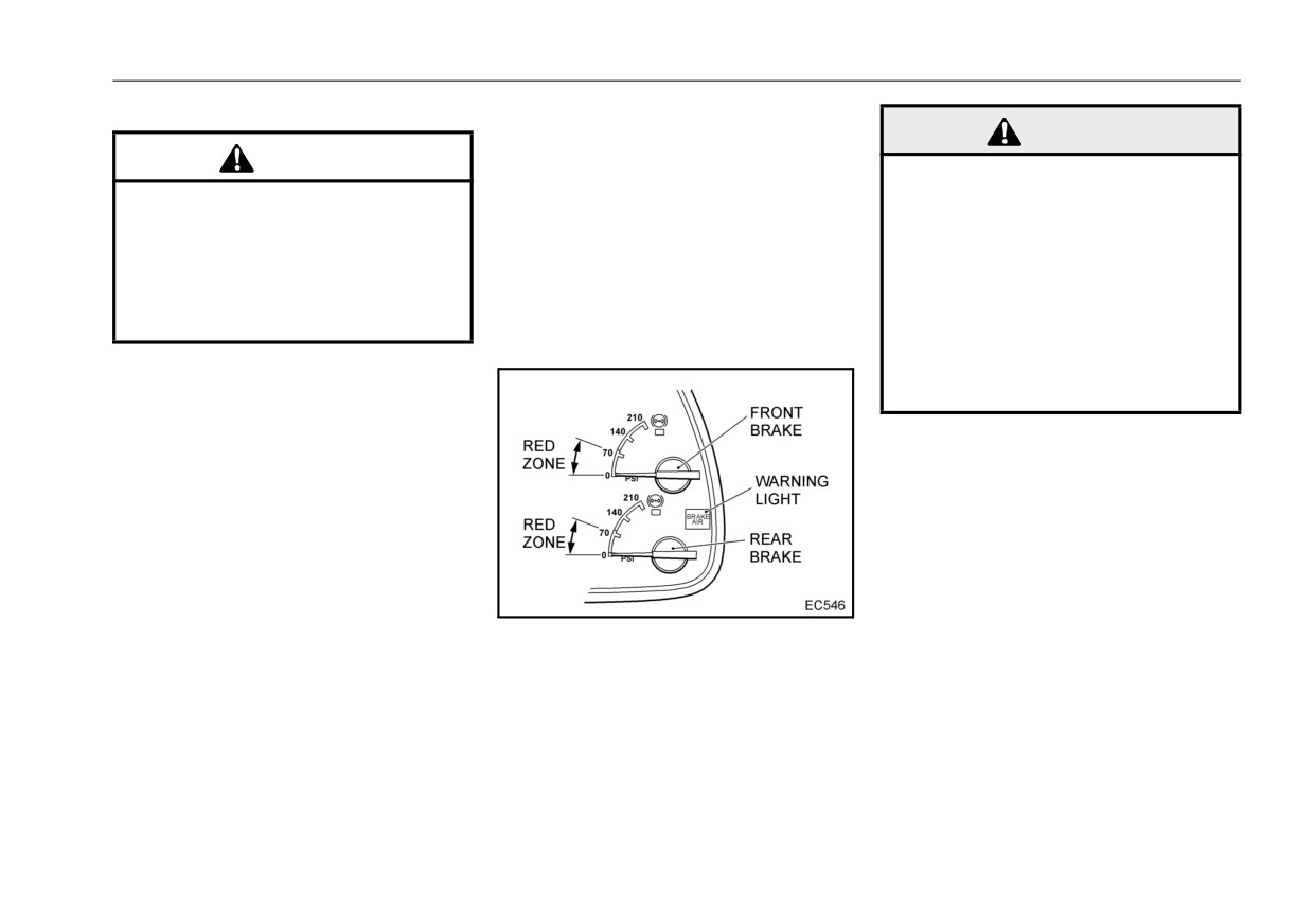
Air pressure gauge
WARNING
This gauge shows the air pressure in
CAUTION
the air reservoir.
z If the air pressure gauge indi-
z Please do not exceed the maxi-
If the indicator shows the standard
cator is in the red zone and
mum allowable rpm. Driving
air pressure while driving, this is nor-
either the warning light illumi-
beyond this range over-
mal.
nates or the warning buzzer
stresses the engine compo-
Normal air pressure is:
sounds, stop driving the vehi-
nents and could cause the
102 - 121 psi (706 - 834 kPa)
cle. Not doing so could lead to
engine to malfunction.
the brakes not working.
(7.2 - 8.5 kgf/cm2)
z Do not drive until the air pres-
sure gauge indicator shows
the normal air pressure.
7 - 8

-------------------------------------------------------------------------------------------------------------------------------------------------------------

INSTRUMENTS AND CONTROLS
Engine Coolant Temperature
z If the coolant temperature signifi-
WARNING
(ECT) gauge
cantly increases, an overheat
warning with a 2-phase indication
z If the cap is removed without
This gauge indicates the engine
(amber: moderate, red: severe) will
allowing the pressure inside
coolant temperature (ECT).
appear.
the cooling system to drop,
you could be burned by hot
steam or hot water, so be very
careful when opening the cap.
CAUTION
z
Do not suddenly stop the
engine when it has overheated.
Doing so could cause the
engine to seize up.
z
When the gauge indicates nothing,
Keep the engine idling until the
z
it is recommended to idle the
the ECT is very cold.
engine coolant temperature
engine until the ECT drops, then
When the gauge indicates
(ECT) drops before turning off
stop the engine and check the
between 1 to 8 point, the ETC is
the engine.
engine coolant level
(ECL), and
normal.
then inspect the cooling system for
z
When the ECT becomes high
leaks.
while another screen is displayed
on the multi-display, a beep will
sound twice and the display will
automatically change to the ECT
gauge (except when other warn-
ings are displayed).
7 - 9

-------------------------------------------------------------------------------------------------------------------------------------------------------------

INSTRUMENTS AND CONTROLS
Diesel exhaust fluid (DEF) gauge
Low level
DEF empty
The DEF gauge indicates the
z When the level in the aftertreat-
z If the level of DEF becomes empty,
approximate amount of DEF in the
ment DEF tank is low, a warning
the DEF warning light blinks. The
aftertreatment DEF tank.
message will be displayed and a
25% of engine torque reduction is
z When the ignition key is turned
warning light will illuminate to warn
simultaneously performed.
OFF position, the indicator returns
the driver.
to E.
z F denotes FULL, and E denotes
EMPTY. Add DEF before the indi-
cator reaches E.
7 - 10

-------------------------------------------------------------------------------------------------------------------------------------------------------------

INSTRUMENTS AND CONTROLS
DEF empty + 1 hour
True empty & Speed limit
CAUTION
z 1 hour after the DEF becomes
z Furthermore, if the warning
z Once the DEF Trigger is
nearly empty, the engine control
changes to the engine control
achieved, the vehicle will be
warning light illuminates, the 40%
warning,
vehicle
speed is
limited to 5 mph (8 km/h) after
of engine torque reduction is per-
restricted to 5 mph (8 km/h).
refuel up to the measurable
formed.
amount, or keeping zero vehi-
cle speed for 20 minutes with
engine off or idle.
7 - 11

-------------------------------------------------------------------------------------------------------------------------------------------------------------

INSTRUMENTS AND CONTROLS
Fuel gauge
Engine oil pressure gauge
The fuel gauge indicates the approx-
This gauge shows the engine oil
imate amount of fuel in the fuel tank.
pressure.
z
When the ignition key is turned
z
The range of 29 to 67 psi (200 to
OFF position, the indicator returns
460 kPa) (2.0 to 4.7 kgf/cm2) is
to E.
shown while the engine is running.
z
F denotes FULL, and E denotes
The pressure could exceed the
EMPTY. Add fuel before the indica-
standard pressure when the oil is
tor reaches E.
cold, but it will return to the stan-
z
If regenerate the DPF when the
dard pressure when the engine
fuel gauge indicates less than E,
warms up.
engine system malfunction might
z
If the engine oil pressure drops
be detected.
below the specified pressure, the
In this case, refill the fuel and
engine oil pressure warning with a
regenerate DPF again, and then
2-phase indication (amber: moder-
confirm that this malfunction is
ate, red: severe) will be displayed
solved.
to notify the driver.
z
For more information regarding the
warning, refer to “Warnings”.
7 - 12

-------------------------------------------------------------------------------------------------------------------------------------------------------------

INSTRUMENTS AND CONTROLS
Voltmeter
Engine oil temperature gauge
NOTE:
z This will not decline below the
This meter operates when the igni-
This gauge shows the engine oil
battery voltage while driving
tion key is in the ON position, and it
temperature.
even if charging is insufficient
shows the battery voltage when the
z The range of 194 to 257 °F (90 to
or inoperable. Always be con-
engine is stopped and the generator
125 °C) is shown while the engine
scious of the meter indicator
charge voltage when the engine is
is running.
and check the state of charging.
running.
z If the engine oil temperature
z The normal value is 12V when the
exceeds the specified tempera-
engine is stopped and 14V when it
ture, the engine oil temperature
is running.
warning a
2-phase indication
z When charging is not possible
(amber: moderate, red: severe) will
while the engine is running, the
be displayed to notify the driver.
charge warning is displayed to
z For more information regarding the
notify the driver of the malfunction.
warning, refer to “Warnings”.
z For more information regarding the
warning, refer to “Warnings”.
7 - 13

-------------------------------------------------------------------------------------------------------------------------------------------------------------

INSTRUMENTS AND CONTROLS
DPF Soot level gauge
DPF ash level gauge
z Indicates the soot accumulation
z Indicates the ash accumulation
level in the diesel particulate filter
(DPF).
(DPF).
z For details on the diesel particulate
z For details on the DPF ash level
filter (DPF), refer to the “DPF sys-
gauge, refer to the “Regular main-
tem” section in
“INSTRUMENTS
tenance for the DPF system” sec-
AND CONTROLS”.
tion in “VEHICLE SERVICE AND
z For details on how to display the
MAINTENANCE”.
gauge, refer to the “Multi-display
z For details on how to display the
monitor” section.
gauge, refer to the “Multi-display
monitor” section.
7 - 14

-------------------------------------------------------------------------------------------------------------------------------------------------------------

INSTRUMENTS AND CONTROLS
MULTI-DISPLAY MONITOR
MTM specification vehicles
The multi-display monitor displays
The multi-display monitor shows
the following information: engine
several kinds of information in each
coolant temperature gauge, calen-
display area.
dar, engine oil pressure and temper-
ature gauges, voltmeter, DPF soot
and ash level gauges, operation con-
z
MTM specification vehicles:
trol display, several maintenance
The left area of the monitor dis
and inspection items. Furthermore,
plays a calendar and the time.
other setting items such as date and
ATM specification vehicles:
language are displayed. If neces-
The left area of the monitor dis-
sary, the multi-display warns the
plays ATM select positions, over-
driver with display items that include
drive off (Allison 1000, 2200, 2500
warnings and warning messages.
ATM specification vehicles
series) and power mode (Allison
3000 series).
z
The center area of the monitor dis-
plays warnings and icons.
z
The right area of the monitor dis-
plays warning messages that oper-
ate simultaneously with icons and
several multi-gauges.
z
The ODO area displays the ODO
meter and other operational mes-
sages.
7 - 15

-------------------------------------------------------------------------------------------------------------------------------------------------------------

INSTRUMENTS AND CONTROLS
The screens of the multi-display monitor can be toggled as follows.
7 - 16

-------------------------------------------------------------------------------------------------------------------------------------------------------------

INSTRUMENTS AND CONTROLS
Changing the screen of the multi-
display monitor
z The initial screen is displayed
when the ignition key is turned to
the ON position.
z The initial screen changes to the
next screen after 2 seconds.
z After the initial screen display dis-
appears, a warning cannot be dis-
Normal mode
While setting
played on the screen for
10
Briefly press the
Press and hold the
Briefly press the
Press and hold the
seconds in order to display the
button (less than 1
button (more than 1
button (less than 1
button (more than 1
second)
second)
second)
second)
gauge.
The value is
The value is continu-
MODE
Mode change
Go to settings
increased by 1
ously increased
The screen returns to
SELECT
Change in order
Go to settings
The digit shifts up
normal
Change sub-
The digit shifts
The screen returns to
RETURN
screens in reverse
Go to settings
down
normal
order
7 - 17

-------------------------------------------------------------------------------------------------------------------------------------------------------------

INSTRUMENTS AND CONTROLS
EACH SCREEN DISPLAY AND
<Clock/Calendar display (ATM
NOTE:
specification vehicles)>
z
Inputting and modifying an item
VALUE INPUT METHOD
cannot be done while a warning
is displayed.
<Engine coolant temperature gauge
display>
To input or modify an item while
the warning is displayed, press
the mode select switch for less
than 1 second so that the warn-
ing display can be temporarily
cancelled.
The screen will return to the
warning display approximately
60 seconds after the mode
select switch is pressed.
<Engine oil pressure, Engine oil
z
Setting is not available while
temperature gauge display>
driving the vehicle.
Park the vehicle in a safe loca-
<DPF soot level gauge display>
tion, and then perform settings
such as calendar change or data
input.
7 - 18

-------------------------------------------------------------------------------------------------------------------------------------------------------------

INSTRUMENTS AND CONTROLS
<Voltmeter display>
1 second while the operation con-
z If the monitor is displaying a warn-
trol screen is displayed. A cursor
ing indicator, the operation control
will be displayed on the thousands
notice will not interrupt the warning
digit.
indicator display. However, when
z Press the mode select switch to
the mode switch is pressed to
change a number.
change the display or the warning
z Press and hold the mode switch to
indicator display is cancelled, the
continuously increase a number.
operation control notice will inter-
z Turn the select switch or return
rupt and blink for 14 seconds.
switch to move the cursor.
If the ignition key is turned to the
The distance can be set by 1 mile
OFF position while the notice
within the range of
0 to
5,000
appears and blinks, the notice will
<Trip management display>
miles.
resume the next time the ignition
key is turned to the ON position.
The remaining driving distance is
decreased by 1 mile.
NOTE:
z
Set the distance to “0” to reset the
z Whenever the select switch or
operation control function.
the return switch is turned for
z
When the remaining driving dis-
more than 1 second while oper-
ating, the display will return to
tance reaches 50%, 10% or 0% of
the normal screen.
the set distance, a notice will
z The cursor returns to the thou-
appear on the screen and blink 14
sands digit after the ones digit.
times.
z The indicated remaining driving
While the monitor displays a
distance may be different from
z
To change the display to the dis-
screen other than the operation
the one that is displayed on trip
tance setting screen, push the
control screen, an operation con-
meter A or B.
mode select switch or the select
trol notice will interrupt the screen
z Setting is not available while
switch for more than 1 second or
and blink for 14 seconds.
driving the vehicle.
turn the return switch for more than
Park the vehicle in a safe loca-
7 - 19

-------------------------------------------------------------------------------------------------------------------------------------------------------------

INSTRUMENTS AND CONTROLS
tion, and then input the dis-
z When the mode switch is pressed
tance.
for more than 1 second while the
hour meter is displayed, the trip
<Hour meter display>
hour meter is reset to “0.0”.
The hour meter indicates the total
NOTE:
running time of the engine at a des-
ignated engine speed. This helps
z The trip hour meter indicates
determine maintenance and inspec-
000.0 while resetting.
tion intervals.
z The trip hour meter does not
count while resetting.
<Maintenance and inspection dis-
play>
<DPF ash level gauge display>
z
When turning the select switch (for
less than
1 second) while the
maintenance and inspection dis-
play appears, the ash level gauge
is displayed. Then, when turning
the switch more (for less than 1
second), the general maintenance
and inspection screen is displayed.
z
The hour meter continuously
z
For details on the DPF ash level
counts and displays up to 199999
gauge, refer to the "Regular main-
hours.
tenance for the DPF" on page 11-
The minimum unit is 1 hour.
70.
z
The trip hour meter displays up to
999.9 hours, and then returns to
0.0 hours.
The minimum unit is 0.1 hour (6
minutes).
7 - 20

-------------------------------------------------------------------------------------------------------------------------------------------------------------

INSTRUMENTS AND CONTROLS
<Several maintenance and inspec-
Differential oil
Engine belt
tion screen displays>
Engine oil
Tire
Coolant
Transmission oil
7 - 21

-------------------------------------------------------------------------------------------------------------------------------------------------------------

INSTRUMENTS AND CONTROLS
Air cleaner element
Air dryer
User setting 2
Fuel filter
User setting 1
User setting 3
z To change the display to the input
screen of the periodic replacement
intervals, push the mode select
switch or the select switch for more
7 - 22

-------------------------------------------------------------------------------------------------------------------------------------------------------------

INSTRUMENTS AND CONTROLS
than 1 second or turn the return
been driven for the set distance) or
NOTE:
switch for more than
1 second
the set date comes, a warning and
z Whenever the select switch or
while the maintenance and inspec-
an item to be replaced are dis-
the return switch is turned for
tion screen is displayed. A cursor
played while the parking brake is
more than 1 second while oper-
will be displayed on the year posi-
applied.
ating, the display will return to
tion.
z
To reset the maintenance and
the normal screen.
z When the mode select switch is
inspection display, set the distance
z The number of the set distance
for replacement may be different
pressed, the number is changed.
to “0” or set the date to the present
from the one that is displayed
The date can be set as follows.
or the past date.
on the trip meter A or B.
Year: 2008 to 2038
z Setting is not available while
Month: January to December
driving the vehicle.
Day: 1 to 31
Park the vehicle in a safe loca-
The distance can be set by 1
tion, and then input the replace-
mile within the range of 1 to 6
ment interval.
digits (from 0 to 999,999 miles).
<Settings display>
The remaining driving distance
is decreased by 1 mile.
z When the mode select switch is
pressed and held, the number is
continuously increased.
z
The remaining driving distance is
z When the select switch or the
preliminarily set to 600 miles in the
return switch is turned, the cursor
user setting 1 as a factory default
is moved.
setting.
The cursor returns to the distance
Contact the nearest authorized UD
position after the date position.
Trucks dealer for the
600 miles
z When the remaining driving dis-
inspection.
tance reaches “0” (the vehicle has
7 - 23

-------------------------------------------------------------------------------------------------------------------------------------------------------------

INSTRUMENTS AND CONTROLS
<Calendar and clock display>
than 1 second in the clock setting
mode, the minutes of the clock will
change to "00" and the display will
return to the normal screen.
When the minutes are in the 00 to
29 range, the minutes will be reset
to “00”.
When the minutes in the 30 to 59
range, the hour will advance by 1
hour and the minutes will be reset
to “00”.
z
To set the calendar and clock dis-
play, press the mode select switch
or the select switch for more than 1
second or turn the return switch for
Clock display: AM 12:00 - 11:59
PM 12:00 - 11:59
more than 1 second while the cal-
endar and clock display is shown.
z
Press the mode select switch while
A cursor will be displayed and blink
the cursor blinks to change the
on the year position.
number.
z
Press and hold the mode select
switch to continuously increase the
number.
z
Turn the select switch or return
switch to move the cursor.
z
When the odo/trip switch located
on the right side is pressed for less
7 - 24

-------------------------------------------------------------------------------------------------------------------------------------------------------------

INSTRUMENTS AND CONTROLS
tion, and then input the time and
while operating, the display will
CAUTION
date.
return to the normal screen.
z
When setting the clock on the
z Language can be selected from
<Language setting screen>
calendar and clock display,
English, Chinese and Japanese.
always place the shift lever
NOTE:
(MTM) or selector (ATM) in the
z
Setting is not available while
neutral position. The combina-
driving the vehicle.
tion meter is equipped with the
Park the vehicle in a safe loca-
shift recognition function that
tion, and then select a language.
automatically recognizes the
transmission
specification
while setting the clock.
If the clock is set while the
transmission is shifted in the R
(Reverse) position, the shift
indicator may not be displayed
z
To select language, push the mode
correctly.
switch or the select switch for more
than 1 second or turn the return
NOTE:
switch for more than
1 second
z Whenever the select switch or
the return switch is turned for
while the language setting screen
more than 1 second while oper-
is displayed. Press the mode
ating, the display will return to
switch to select a language. The
the normal screen.
selected language will blink.
z The cursor returns to the year
z
When the mode switch or the
position after the minute posi-
select switch is pressed for more
tion.
than 1 second or the return switch
z Setting is not available while
is turned for more than 1 second
driving the vehicle.
Park the vehicle in a safe loca-
7 - 25

-------------------------------------------------------------------------------------------------------------------------------------------------------------

INSTRUMENTS AND CONTROLS
WARNINGS AND INDICATORS
Display
Name
Page
Mark
Color
Message
Multi-display
Engine system
Red or
malfunction
Engine system
7-38
Amber
warning
Display
Contact Dealer (or
Name
Page
Check at Dealer)
Mark
Color
Message
Communication line
Engine communica-
Engine overheat
error
Red or
7-9
tion malfunction
7-40
Overheat warning
warning
Amber
Reduce coolant
12-1
Check at Dealer
temp
Amber
DEF tank is empty
DEF level low
DEF low level
DEF low level
warning (Low level)
Vehicle speed
warning (True empty
7-10
Re-Fill DEF Tank
limited
& Speed limit)
DEF tank near empty
DEF low level
Re-Fill DEF tank
Engine is derated
warning
Insufficient DEF
Amber
7-10
DEF insufficient
(Near empty)
Re-Fill DEF tank
quality or failure
quality warning
DEF tank is empty
(Initial detected)
DEF low level
Contact Dealer
Before Re-Fueling
warning
Insufficient DEF
(True empty))
DEF insufficient
Re-Fill DEF tank
quality or failure
quality warning
Reduce engine
Engine overrun
Amber
Engine is derated
(1 hour after)
7-34
Red
7-31
revolution
warning
Contact Dealer
Charging system
Insufficient DEF
error
quality or failure
DEF insufficient
Red
Charge warning
7-32
quality warning
Check generator belt
Vehicle speed
limited
(4 hours after)
Contact Dealer
Contact Dealer
Engine oil pressure
is low
Red or
Engine oil pressure
7-32
Amber
Contact Dealer (or
warning
Check at Dealer)
Engine oil temp too
Red or
high
Engine oil tempera-
7-37
Amber
Reduce engine oil
ture warning
temperature
7 - 26

-------------------------------------------------------------------------------------------------------------------------------------------------------------

INSTRUMENTS AND CONTROLS
Display
Display
Name
Page
Name
Page
Mark
Color
Message
Mark
Color
Message
Insufficient DEF
SCR system tamper-
Starter overheat
Starter overheat
Amber
10-4
quality or failure
ing warning
warning
Waiting time
Contact Dealer
(Initial detected)
PTO is operation
PTO engine start
Insufficient DEF
Amber
10-4
SCR system tamper-
Engine start is not
interrupt warning
quality or failure
possible
ing warning
Amber
Engine is derated
(1 hour after)
7-35
Transmission oil
Contact Dealer
temp too high
ATM fluid
Red
7-41
temperature warning
Insufficient DEF
Reduce oil
quality or failure
SCR system tamper-
temperature
Vehicle speed
ing warning
ATM system error
ATM system
Red
7-42
limited
(4 hours after)
Check at Dealer
warning
Contact Dealer
Engine system
Engine system
Red or
malfunction
3-22
SCR system fault
DPF system warning
Amber
malfunction
7-37
Amber
Contact Dealer (or
7-74
warning
Check at Dealer
Check at Dealer)
Vehicle electrical
DPF regenerating
3-21
Amber
DPF is regenerating
sys. malfunction
Vehicle electrical
warning
7-72
Red or
system malfunction
7-39
Amber
Contact Dealer (or
warning
Regeneration
DPF regeneration
Amber
7-72
Check at Dealer)
system is disabled
restriction warning
Communication line
Vehicle electrical
DPF maintenance
DPF maintenance
3-23
error
system communica-
Amber
Amber
7-40
tion malfunction
Check at Dealer
warning
11-71
Check at Dealer
warning
IDLE
Auto engine shut
Idle shutdown
Amber
10-38
Communication line
Meter communica-
STOP
down
information
Amber
error
tion malfunction
7-39
O/D
ATM O/D OFF
warning
Amber
-
7-52
Check at Dealer
OFF
indicator light
Maintenance and
ATM Power mode
POWER
Amber
-
7-52
Amber
“Item to be replaced”
inspection screen
7-23
indicator light
display
Transmission PTO
Amber
PTO is in operation
7-64
indicator
7 - 27


Content      ..     2      3      4      5     ..