Takeuchi Compact Excavator TB014 (11410001~), TB016 (11610001~). Operators Manual - page 5
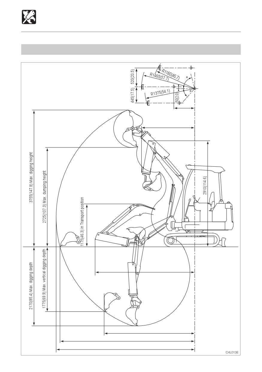
SPECIFICATIONS
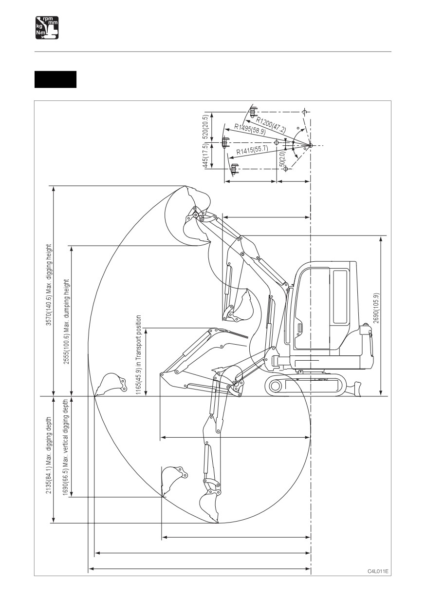
Operating Range
TB014
Equipped with Cab and 1040 mm (41 in.) Arm
Units: mm (inches)
Values are indicated in units of mm, inches in( ).
75
Bucket offset
50
880(34.6)
575
(22.6)
Front slewing radius
1490(58.7)
2545(100.2) in Transport position
2520(99.2)
3660(144.1) Max. ground digging radius
3765(148.2) Max. digging radius
161
SPECIFICATIONS
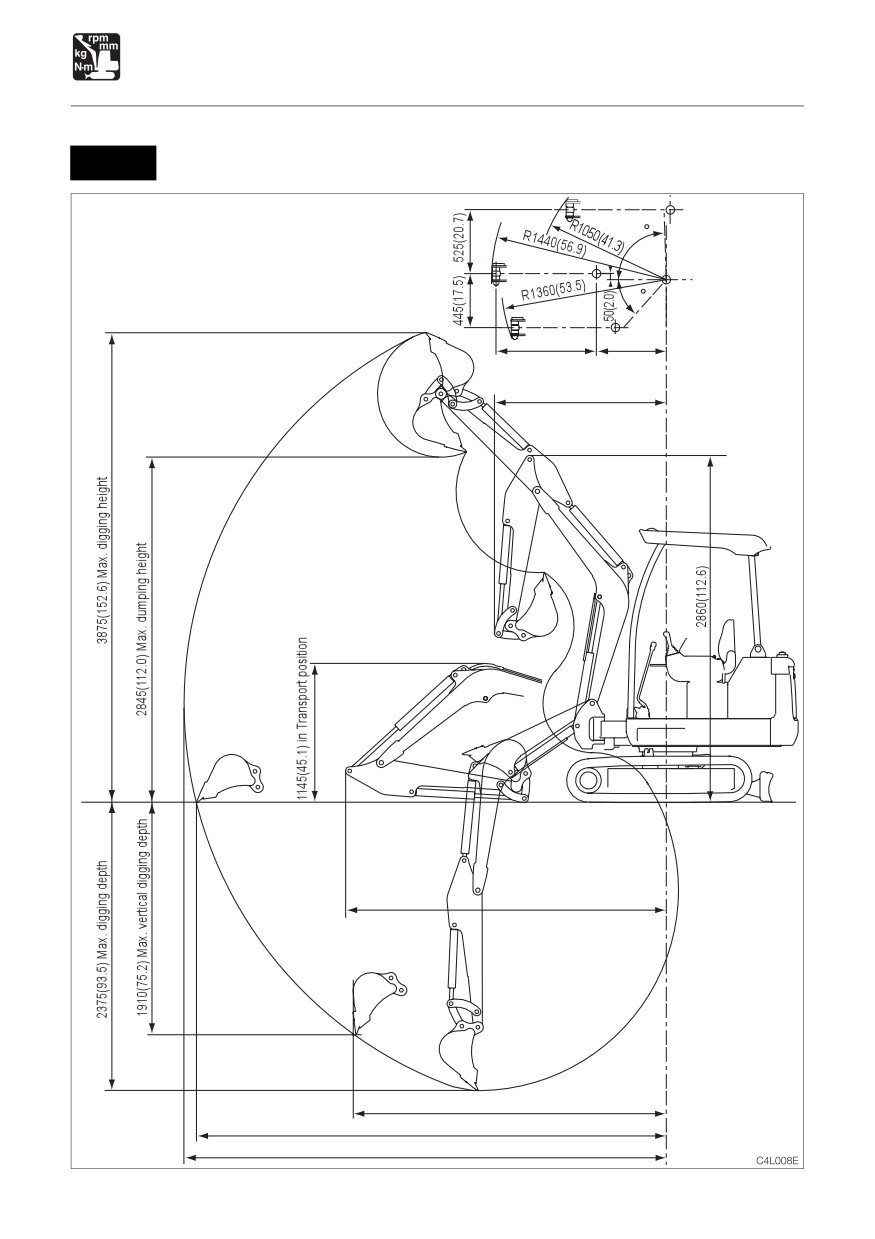
Operating Range
TB016
Equipped with Canopy and 1130 mm (44 in.) Arm
Units: mm (inches)
Values are indicated in units of mm, inches in( ).
90
Bucket offset
50
825
(32.5)
575(22.6)
Front slewing radius
1435(56.5)
2665(104.9) in Transport position
2600(102.4)
3890(153.1) Max. ground digging radius
3990(157.1) Max. digging radius
162
SPECIFICATIONS
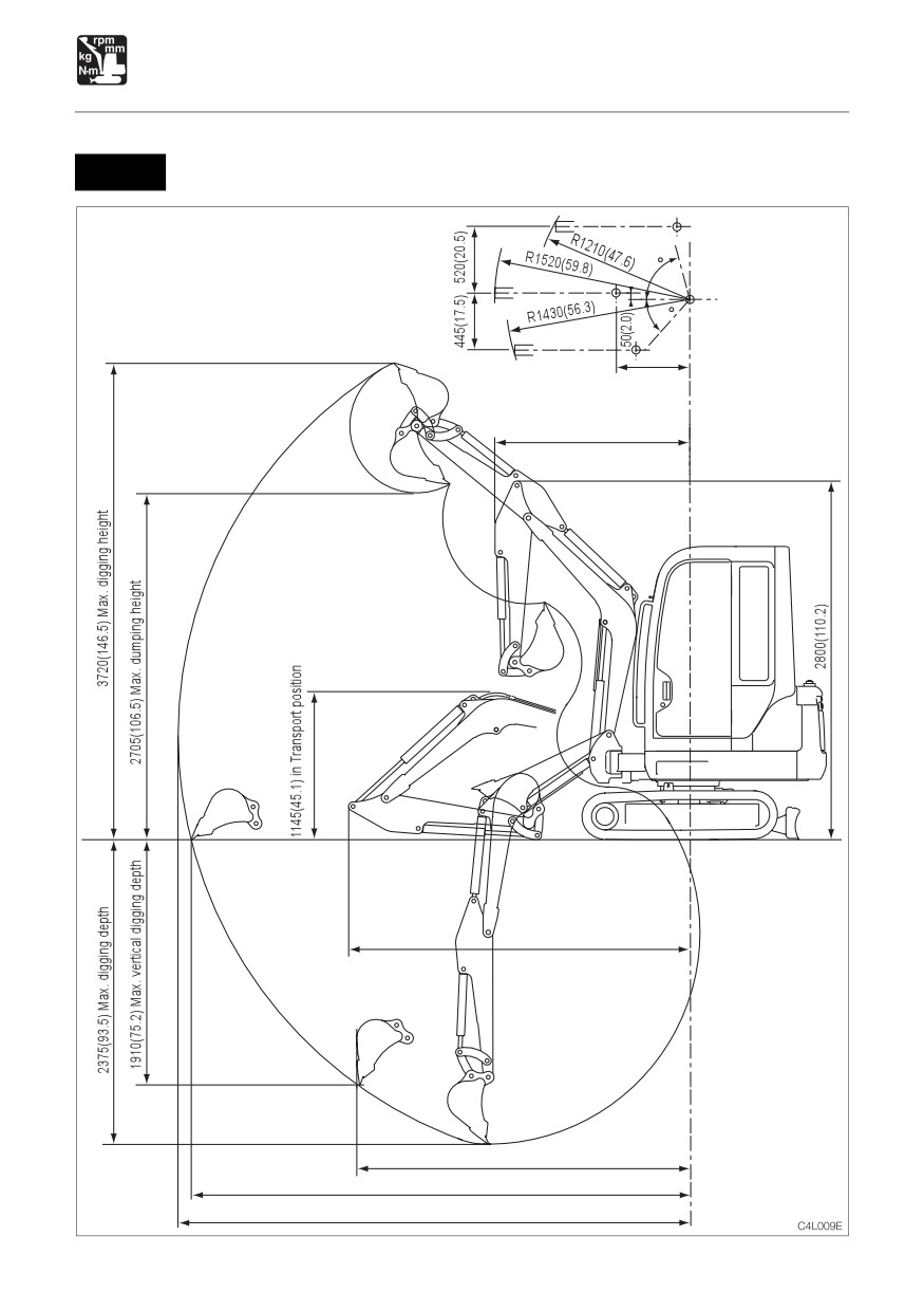
Operating Range
TB016
Equipped with Cab and 1130 mm (44 in.) Arm
Units: mm (inches)
Values are indicated in units of mm, inches in( ).
75
Bucket offset
50
575
(22.6)
Front slewing radius
1520(59.8)
2665(104.9) in Transport position
2600(102.4)
3890(153.1) Max. ground digging radius
3990(175.1) Max. digging radius
163
164
SPECIFICATIONS
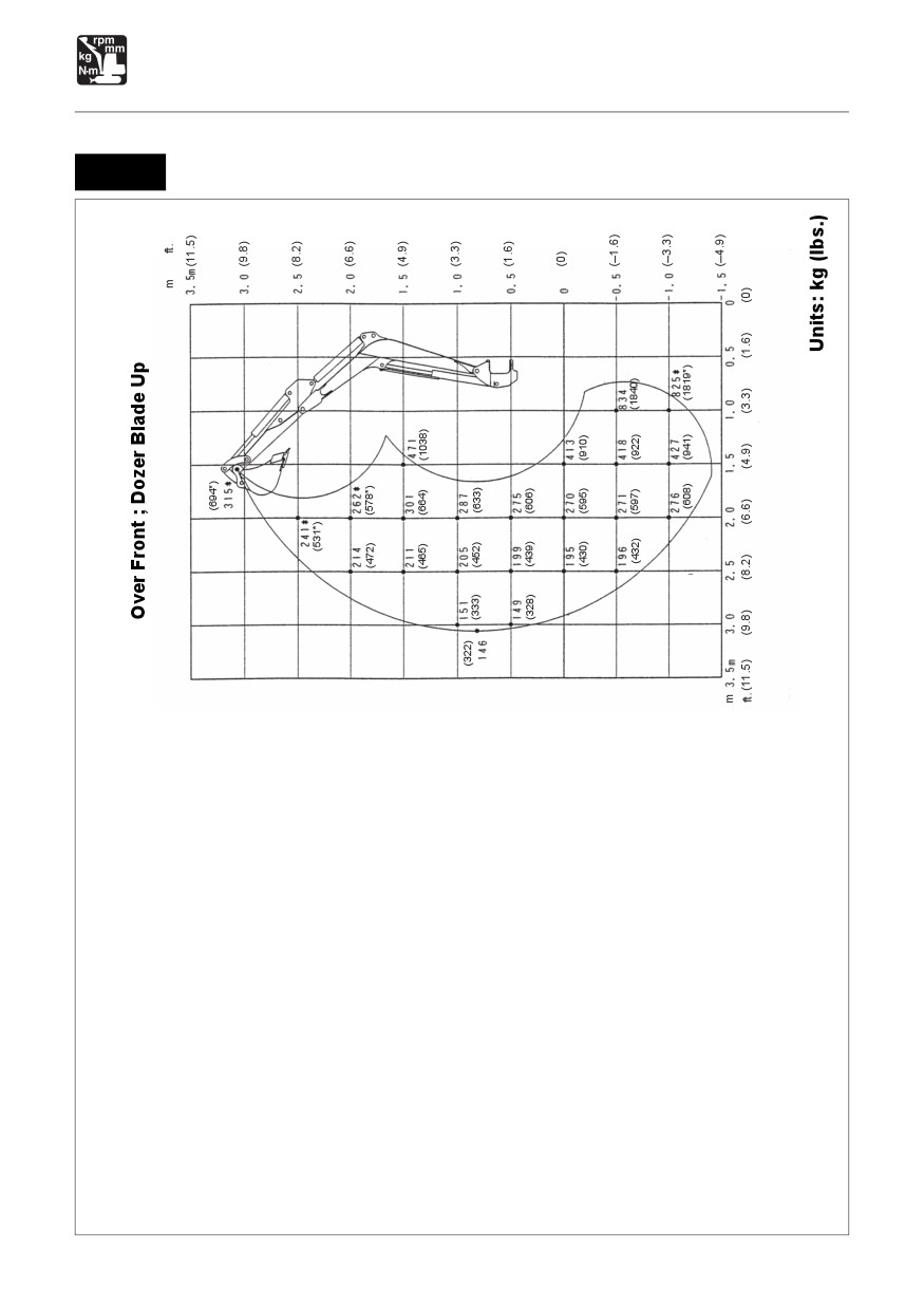
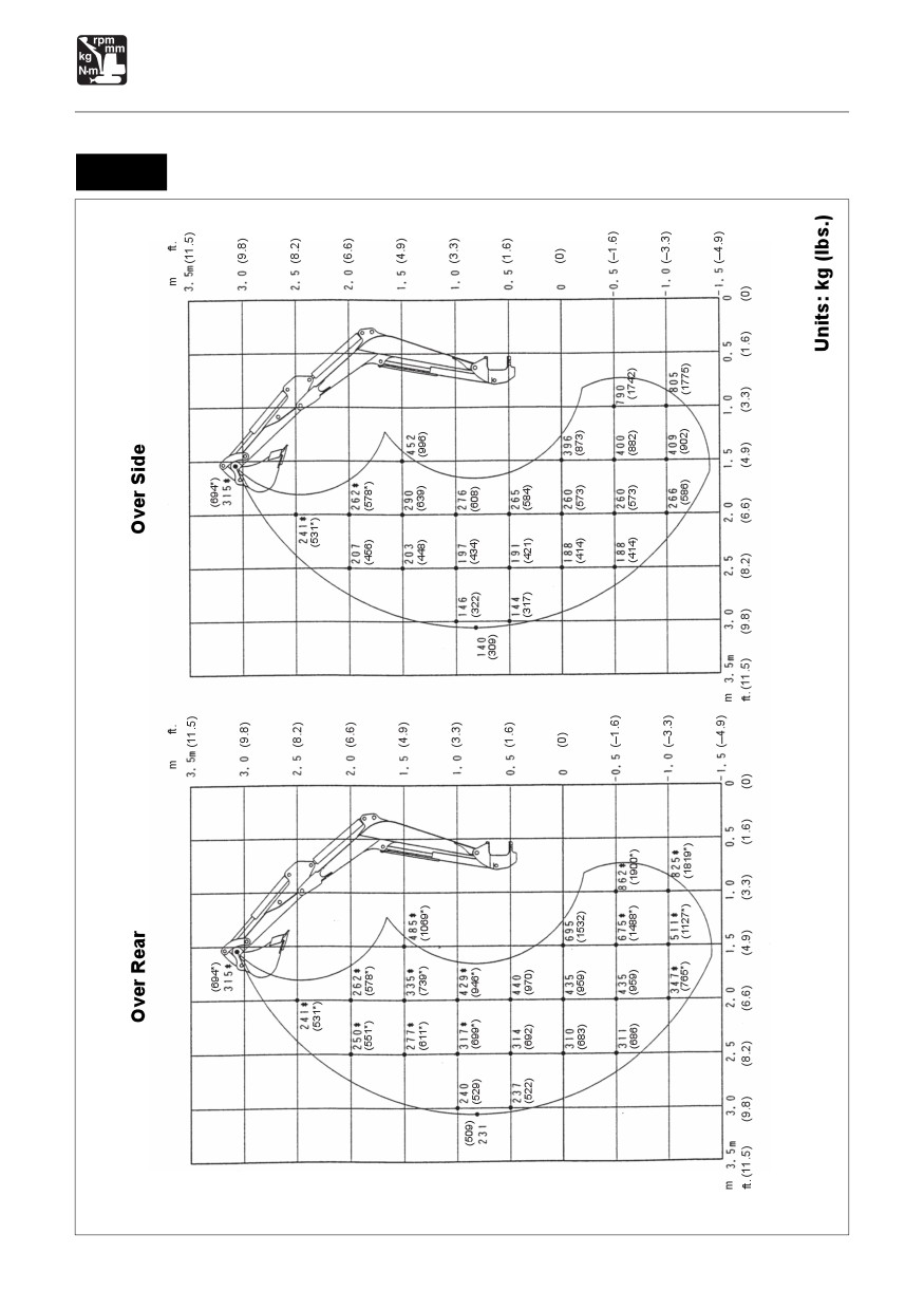
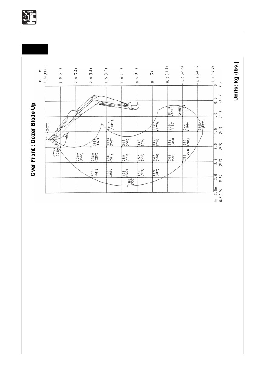
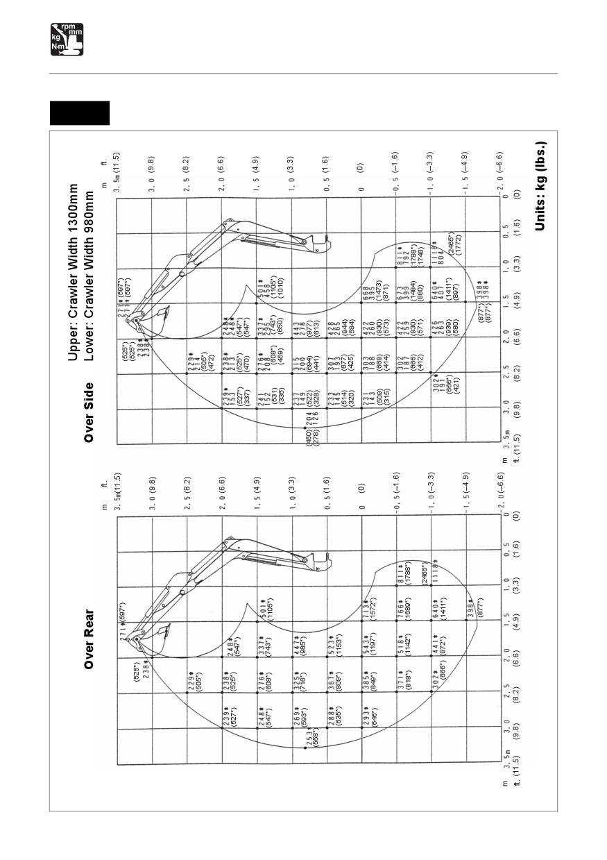
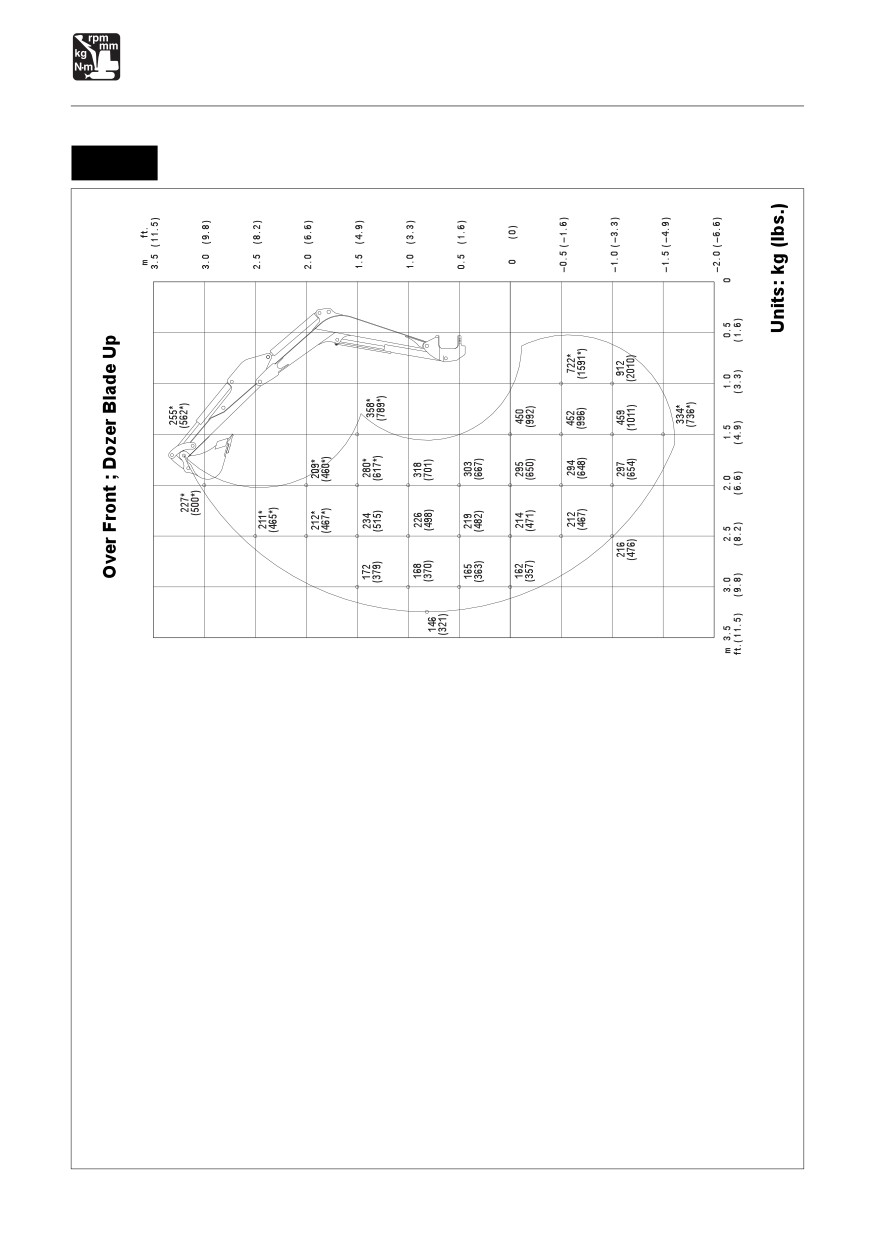
Lifting Capacities
Rated lift capacity chart
¡ The loads in the charts do not exceed 87% of hydraulic lift capacity or 75% of tipping load.
¡ Rated lift capacities limited by rated hydraulic lift capacity are identified by an asterisk(*)
¡ The mass of slings and any auxiliary lifting devices shall be deducted from the rated load
to determine the net load that may be lifted.
¡ The load point is the bucket hinge pin, and the bucket posture is with the standard bucket
completely retracted under the arm.
¡ Units: kg (lbs.)
Load hooking system
A load hooking system with all of the following capacities must be provided and used.
1. A system which can withstand a weight of two times the rated lift capacity no matter at
what position the load is applied.
2. A system in which there is no risk of the lifted load falling from the hooking device, for
example one equipped with a hook slippage prevention device.
3. A system in which there is no risk of the hooking system slipping from the hoe attachment.
WARNING
¡ DO NOT attempt to lift or hold any load that is greater than these rated values at
their specified load radii and height.
¡ All rated lift capacities are based on the machine being level and on a firm supporting
surface. For safe working loads, the user is expected to make due allowance for the
particular job conditions such as soft or uneven ground, non-level condition, side
loads, hazardous conditions, experience of personnel, etc. The operator and other
personnel should fully acquaint themselves with the operator’s manual furnished
by the manufacturer before operating this machine, and rules for safe operation of
equipment shall be adhered to at all times.
165
SPECIFICATIONS
Lifting Capacities
Equipped with 830 mm (33 in.) Arm
TB014
C4K0091
166
SPECIFICATIONS
Lifting Capacities
Equipped with 830 mm (33 in.) Arm
TB014
C4K010
167
SPECIFICATIONS
Lifting Capacities
Equipped with 930 mm (37 in.) Arm
TB016
C4K0111
168
SPECIFICATIONS
Lifting Capacities
Equipped with 930 mm (37 in.) Arm
TB016
C4K012
169
SPECIFICATIONS
Lifting Capacities
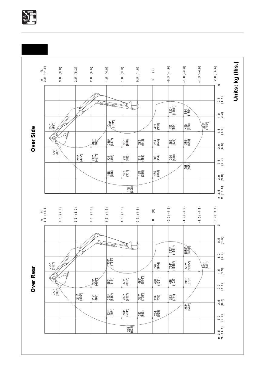
Equipped with 1040 mm (41 in.) Arm
TB014
C4K0151
170
SPECIFICATIONS
Lifting Capacities
Equipped with 1040 mm (41 in.) Arm
TB014
C4K016
171
SPECIFICATIONS
Lifting Capacities
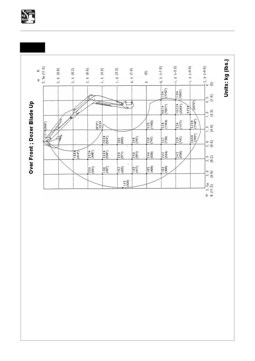
Equipped with 1130 mm (44 in.) Arm
TB016
C4K0131
172
SPECIFICATIONS
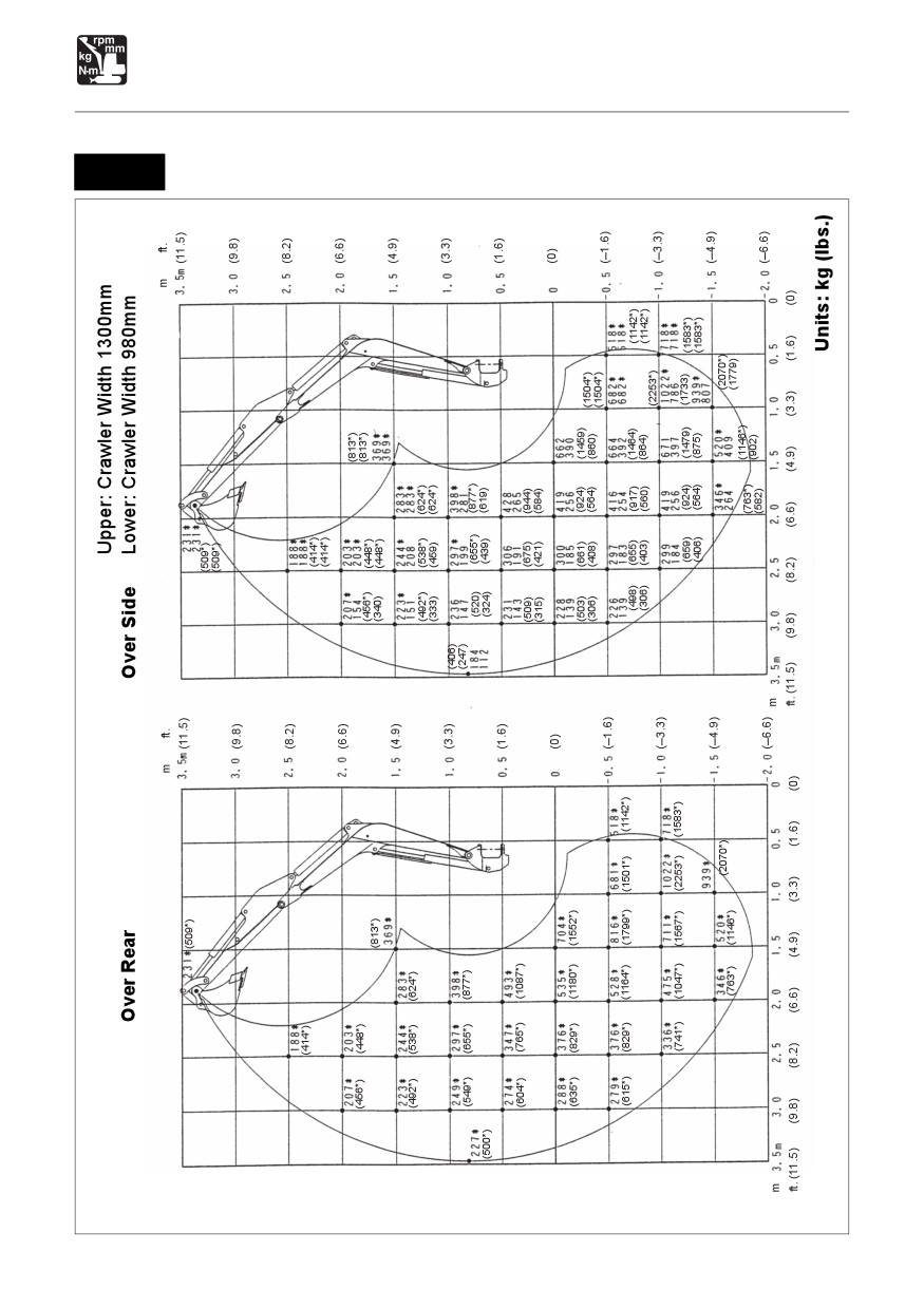
Lifting Capacities
TB016
Equipped with 1130 mm (44 in.) Arm
C4K014
173
SPECIFICATIONS
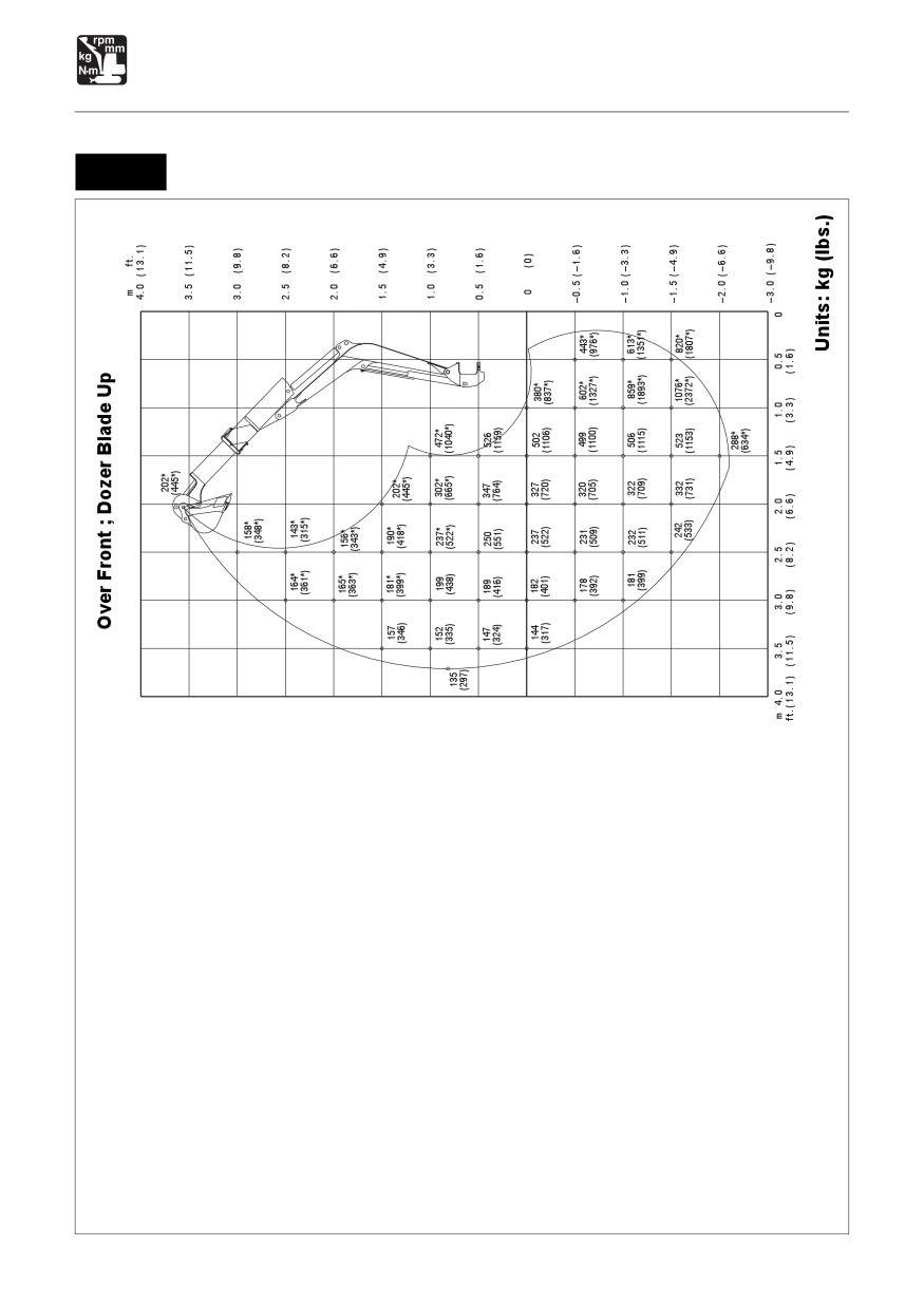
Lifting Capacities
TB016
Equipped with Telescopic Arm (Fully Extended Arm)
C4K0171
174
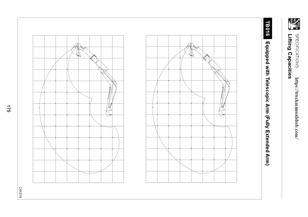
Upper: Crawler Width 1300mm
Over Rear
Over Side Lower: Crawler Width 980mm
m ft.
m ft.
4.0
(13.1)
4.0
(13.1)
202* (445*)
202*
202* (445*)
(445*)
3.5
(11.5)
3.5
(11.5)
3.0
(9.8)
3.0
(9.8)
158*
158* (348*)
(348*)
158* (348*)
2.5
(8.2)
2.5
(8.2)
164*
143*
164*
143* (315*)
(361*)
(315*)
164*
143* (315*)
(361*)
(361*)
2.0
(6.6)
2.0
(6.6)
165*
156*
165*
156*
(363*)
(343*)
165*
156*
(363*)
(343*)
(363*)
(343*)
1.5
(4.9)
181*
190*
1.5
(4.9)
178*
181*
190*
202*
178*
202*
118
160
190*
202*
(392*)
(399*)
(418*)
(445*)
(392*)
(399*)
(418*)
(445*)
(260)
(352)
(418*)
(445*)
1.0
(3.3)
169
188*
205*
237*
472*
1.0
(3.3)
188*
205*
237*
302*
472*
302*
186*
(414*)
(451*)
(522*)
(665*)
(1040*)
99
113
151
205
292
449
(410*)
(372)
(414*)
(451*)
(522*)
(665*)
(1040*)
(218)
(249)
(332)
(451)
(643)
(989)
0.5
(1.6)
183
231*
286*
398*
0.5
(1.6)
199*
231*
286*
398*
694*
667
(438*)
(509*)
(630*)
(877*)
(1529*)
108
141
188
260
384
(403)
(509*)
(630*)
(877*)
(1470)
(238)
(310)
(414)
(573)
(846)
0
(0)
180
226*
295
410
641
0
(0)
205*
250*
321*
456*
752*
380*
380*
(451*)
(551*)
(707*)
(1005*)
(1657*)
(837*)
105
134
176
241
362
380*
(396)
(498*)
(650)
(903)
(1413)
(837*)
(231)
(295)
(388)
(531)
(798)
(837*)
-0.5
(-1.6)
222
289
402
638
602*
443*
–0.5 (-1.6)
255*
334*
471*
754*
602*
443*
(562*)
(736*)
(1038*)
(1662*)
(1327*)
(976*)
130
170
234
359
602*
443*
(489)
(637)
(886)
(1406)
(1327*)
(976*)
(286)
(374)
(515)
(791)
(1327*)
(976*)
-1.0
(-3.3)
225
290
404
646
859*
613*
-1.0
(-3.3)
232*
318*
445*
685*
859*
613*
(511*)
(701*)
(981*)
(1510*)
(1893*)
(1351*)
133
170
236
366
734
613*
(496)
(639)
(890)
(1424)
(1893*)
(1351*)
(293)
(374)
(520)
(806)
(1618)
(1351*)
820*
-1.5
(-4.9)
251*
367*
551*
1076*
820*
–1.5 (-4.9)
251*
367*
551*
1076*
180
246
382
763
820*
(553*)
(809*)
(1214*)
(2372*)
(1807*)
(553*)
(809*)
(1214*)
(2372*)
(1807*)
(396)
(542)
(842)
(1682)
(1807*)
-2.0
(-6.6)
288*
-2.0
(-6.6)
288*
288*
(634*)
(634*)
(634*)
-3.0
(-9.8)
-3.0
(-9.8)
m
4.0
3.5
3.0
2.5
2.0
1.5
1.0
0.5
0
m
4.0
3.5
3.0
2.5
2.0
1.5
1.0
0.5
0
ft.(13.1)
(11.5)
(9.8)
(8.2)
(6.6)
(4.9)
(3.3)
(1.6)
ft.(13.1)
(11.5)
(9.8)
(8.2)
(6.6)
(4.9)
(3.3)
(1.6)
Units: kg (lbs.)
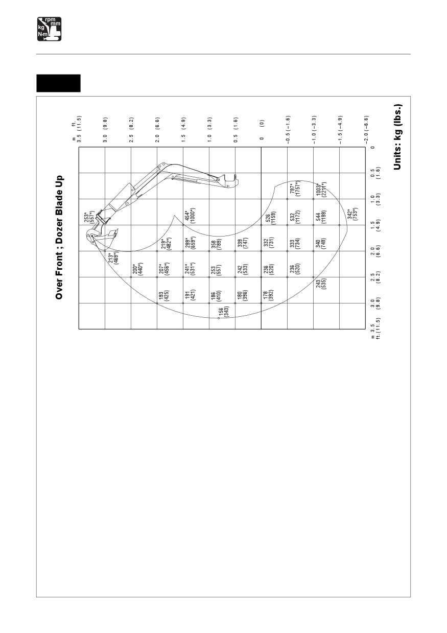
SPECIFICATIONS
Lifting Capacities
TB016
Equipped with Telescopic Arm (Fully Retracted Arm)
C4K0191
176
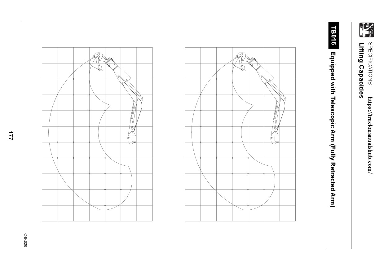
Upper: Crawler Width 1300mm
Over Rear
Over Side
Lower: Crawler Width 980mm
m ft.
m
ft.
3.5
(11.5)
3.5
(11.5)
253*
253* (557*)
(557*)
253* (557*)
3.0
(9.8)
3.0
(9.8)
213*
213*
(469*)
213*
(469*)
(469*)
2.5
(8.2)
2.5
(8.2)
200*
200*
(440*)
200*
(440*)
(440*)
2.0
(6.6)
2.0
(6.6)
207*
207*
219*
207*
207*
219*
(456*)
(456*)
(482*)
145
207*
219*
(456*)
(456*)
(319)
(456*)
(482*)
(482*)
1.5
(4.9)
1.5
(4.9)
214*
241*
299*
454*
214*
241*
299*
454*
(471*)
(531*)
(659*)
(1000*)
143
202
295
454*
(471*)
(531*)
(659*)
(1000*)
(315)
(445)
(650)
(1000*)
1.0
(3.3)
1.0
(3.3)
233*
285*
398*
230
285*
398*
(513*)
(628*)
(877*)
194
138
190
270
218*
113
(507)
(480*)
(427)
(628*)
(877*)
(304)
(418)
(595)
(249)
0.5
(1.6)
0.5
(1.6)
250*
323*
468*
225
300
422
(551*)
(712*)
(1031*)
133
180
253
(496)
(661)
(930)
(293)
(396)
(557)
0
(0)
0
(0)
254*
340*
487*
222
294
415
667
(559*)
(749*)
(1073*)
701*
130
175
246
(1545*)
384
(489)
(648)
(914)
(1470)
(286)
(385)
(542)
(846)
-0.5
(-1.6)
–0.5
(-1.6)
327*
462*
693*
797*
294
415
674
797*
(720*)
(1018*)
(1527*)
(1757*)
174
246
390
797*
(648
(914)
(1485)
(1757*)
(383)
(542)
(859)
(1757*)
-1.0
(-3.3)
–1.0
(-3.3)
261*
390*
572*
1003*
261*
390*
572*
1003*
(575*)
(859*)
(1261*)
(2211*)
181
253
401
816
(575*)
(859*)
(1261*)
(2211*)
(399)
(557)
(884)
(1798)
-1.5
(-4.9)
–1.5
(-4.9)
342*
342*
342*
(753*)
(753*)
(753*)
-2.0
(-6.6)
–2.0
(-6.6)
m
3.5
3.0
2.5
2.0
1.5
1.0
0.5
0
m
3.5
3.0
2.5
2.0
1.5
1.0
0.5
0
ft.(11.5)
(9.8)
(8.2)
(6.6)
(4.9)
(3.3)
(1.6)
ft.(11.5)
(9.8)
(8.2)
(6.6)
(4.9)
(3.3)
(1.6)
Units: kg (lbs.)
178
OPTIONS
General Precautions
180
Safety Signs (Decals)
182
Biodegradable Oil
184
Switching the Lever Pattern
185
Attachment Combination Table
186
Telescopic Arm
187
Hydraulic Breaker
192
Three-Hole Bucket
194
High-back Seat
197
Travel Alarm
199
Radio (for EU)
200
Batterie Switch
204
179
OPTIONS
General Precautions
Precautions on Safety
WARNING
Heed the following when removing or installing an attachment or option:
¡ Consult with a Takeuchi dealer before installing optional attachments.
¡ Do not use attachments that have not been approved by Takeuchi or a Takeuchi
dealer. Doing so may compromise safety or adversely affect the machine’s operation
or service life.
¡ Takeuchi will not be held responsible for any injuries, accidents or damage to
products caused by the use of a non-approved attachment.
¡ Choose a flat, hard surface to perform the operations. Also make sure there is enough
light and good ventilation.
¡ Clean the area, remove any articles that may get in the way or be dangerous, and
remove any spilt oil or grease.
¡ When performing lifting operations, determine a person to lead the operations and
always follow that person’s instructions.
• Follow the leader’s instructions on operating methods and procedures.
• Determine a signal leader and heed this person’s signals.
¡ When removing or installing the hoe attachment, place it in a stable position so that
it does not tip over.
¡ Due to the risk of loads falling and/or hitting people, do not allow unauthorized
personnel in the work area.
¡ Use the crane to carry heavy objects (25 kg (55 lb.) or greater).
¡ When removing heavy parts, be sure to prop them up before removing them. When
lifting them with a crane, be careful to balance them properly.
¡ Operating with loads suspended with the crane is dangerous. Place loads on a
stand and check for safety.
¡ When attaching the boom or arm, failure to follow proper procedures could result in
serious damage. Consult with a Takeuchi dealer beforehand.
Precautions on Installing Attachments
After replacing optional attachments or other special attachments, test-run them, then inspect
the hydraulic oil level and add oil if necessary.
In addition, consult with a Takeuchi dealer for details of removal and installation procedures.
180
OPTIONS
General Precautions
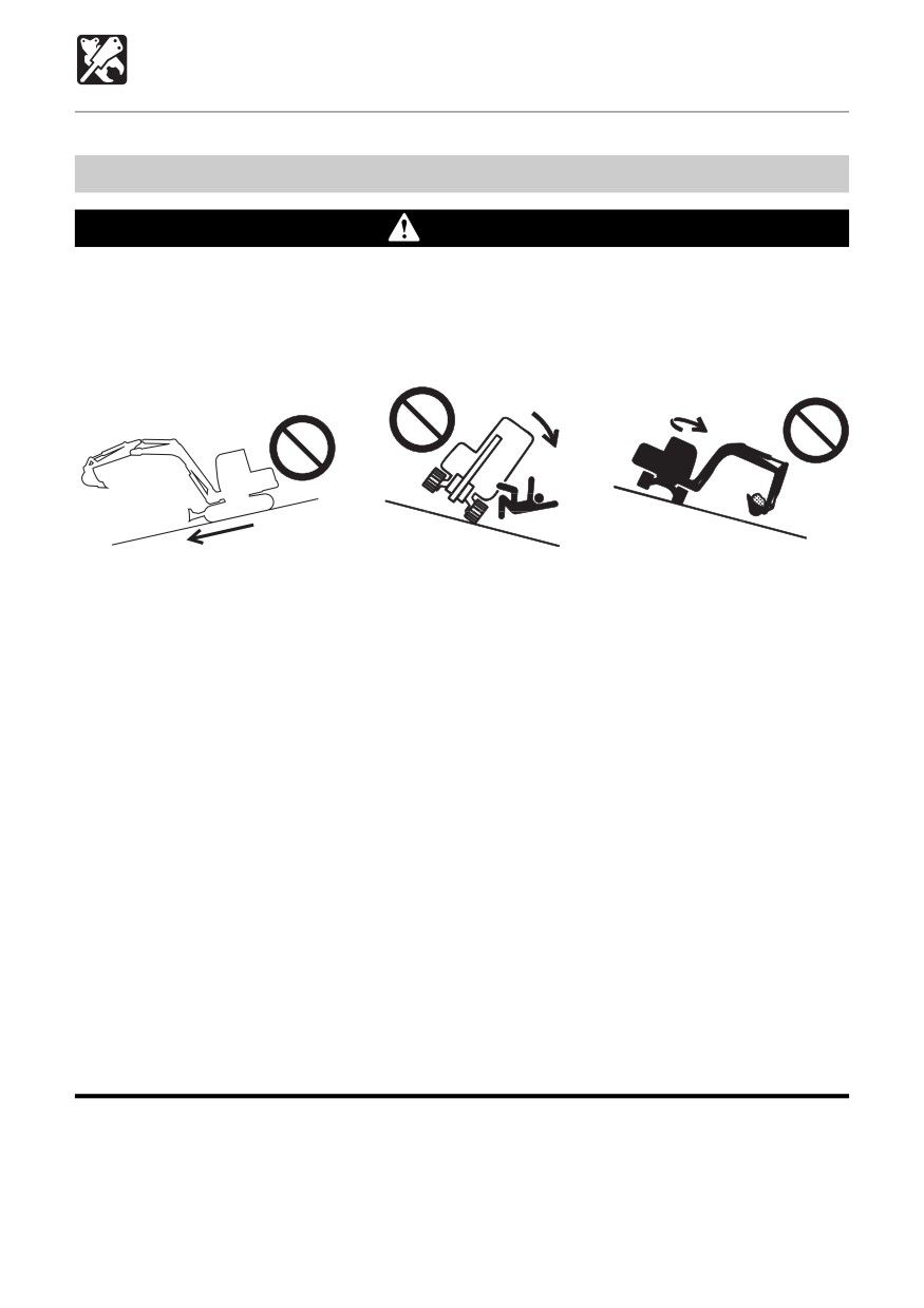
Precautions on Operating Attachments
WARNING
Long attachments reduce machine stability. When traveling down steep slopes or
slewing on slopes, the machine may loose its balance and tip over.
The following operations are particularly dangerous. Do not perform them.
¡ Traveling down slopes
¡ Traveling across slopes
¡ Slewing on slopes
with the attachment lifted
OE3A2531
OE3A271
OE3A331
¡ When heavy attachments are installed, the overslew (the distance from where the
operation to stop slewing is performed until slewing stops completely) increases
and mistakes in judgment may result in the attachment hitting surrounding objects.
Allow for plenty of room between the attachment and obstacles.
In addition, the natural drop (the gradual dropping of the attachment under its own
weight when it is stopped in midair) also increases when heavy attachments are
installed.
¡ The machine can tip over more easily in the lateral direction than in the longitudinal
direction.
• Do not slew (swing) sideways with excessive weight at the front. In particular do
not slew sideways on slopes.
• The front is heavier for machines equipped with breakers, crushers or telescopic
arms than for machines equipped with the standard bucket. Do not operate such
machines sideways, especially with the digging arm (boom) downhill.
¡ When a long arm or a telescopic arm is installed, the operating range suddenly
increases and mistakes in judgment may result in the attachment hitting surrounding
objects. Allow for plenty of room between the attachment and obstacles.
¡ Add an extra weight when using a long arm or a telescopic arm.
¡ Install a swing stopper when a bucket wider than the standard bucket, long arm and
telescopic arm is installed and when using a cab version.
181
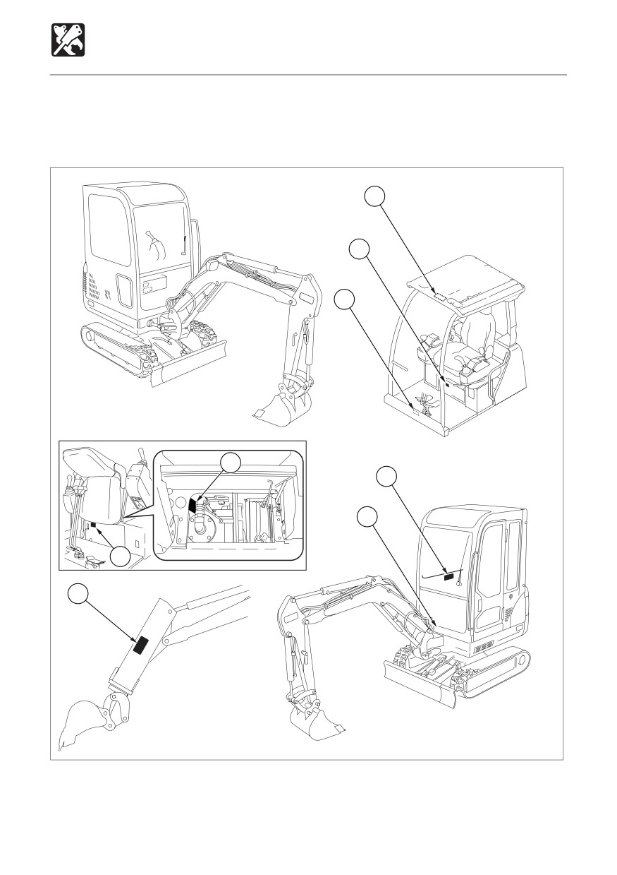
OPTIONS
Safety Signs (Decals)
Keep all safety signs clean and legible.
Replace all missing, illegible or damaged safety and warning signs.
There are other safety signs in addition to the ones listed here. Treat them in the same way.
3
4
2
1
3
2
4
3
C4L0072
182
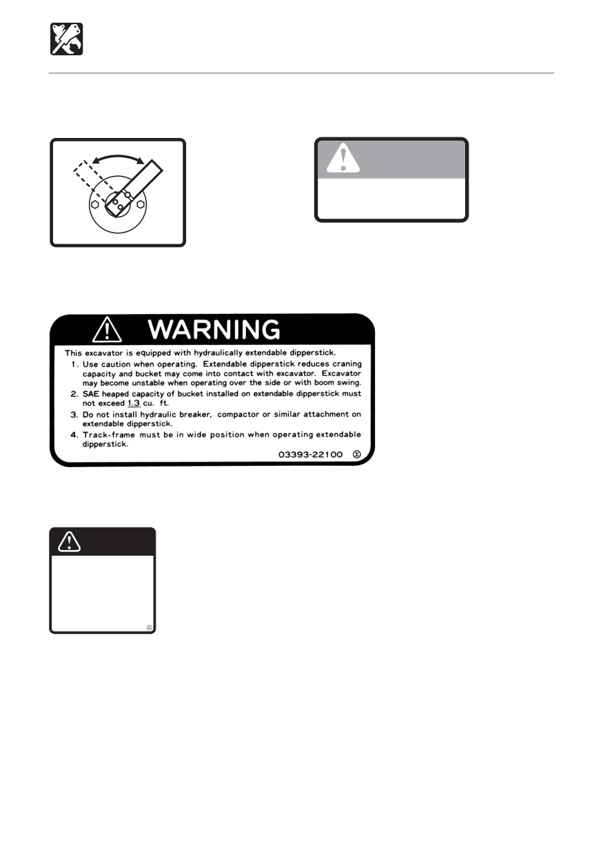
OPTIONS
Safety Signs (Decals)
1. A-G selector valve
2. Check the lever pattern
No.03593-32200
No.03593-32300
A
G
(ISO)
WARNING
Check what type of lever control
arrangement you are operating
with before beginning operations.
03593-32300
03593-32200
3. No.03393-22100
4. No.05693-53810
CAUTION
Setting this switch to the “OFF”
position will shut down all of
the electrical circuits and the
memory of the radio preset
tuning buttons will be deleted.
05693-53810
183
OPTIONS
Biodegradable Oil
Biodegradable oil
Biodegradable oil is a new type of hydraulic oil that is decomposed into carbon dioxide and
water by microorganisms in the soil and water. It is highly safe for living organisms and offers
advantages in terms of environmental protection.
¡ Recommended biodegradable oil: Mobile EAL Envirosyn 46H (an ester synthetic oil).
When replacing the hydraulic oil with biodegradable oil, use the above or an equivalent oil.
Note that other oils, even other brands of ester synthetic oils, may damage O-rings, packings
and seals. Takeuchi products shipped with the optional biodegradable oil are shipped with
the above brand of oil.
¡ When switching from a mineral oil to a biodegradable oil, the parking brake torque decreases
by about 30%.
Replacing the hydraulic oil with biodegradable oil
Mixing mineral oil with biodegradable oil will result in a decrease of the hydraulic oil’s
performance as well as a decrease in biodegradability and safety. The hydraulic oil system
must be flushed as described below before supplying the biodegradable oil. This operation is
dangerous and requires experience. Have it performed by a Takeuchi sales or service outlet.
Flushing
¡ To be performed by a Takeuchi sales or service outlet
1. Drain the hydraulic oil (mineral oil) from the hydraulic tank and Clean the inside of the tank
and suction strainer.
Refer to page 127 “Replacing the Hydraulic Oil and Cleaning the Suction Strainer”.
2. Remove the cylinder hoses and drain the hydraulic oil (mineral oil) from inside the cylinders.
Hydraulic tank: Approx. 23 liters (24.3 US.qt.)
Total of cylinders: Approx. 2 liters (2.1 US.qt.)
Total amount of oil: Approx. 25 liters (26.4 US.qt.)
3. Supply new biodegradable oil to the hydraulic tank.
4. Bleed the air from the pump and cylinders and pressurize the hydraulic tank.
5. Operate the hydraulic devices for 30 minutes.
6. Drain the biodegradable oil from the tank and cylinders.
7. Replace the hydraulic oil return filter with a new filter.
8. Repeat steps 3 and 4.
9. Operate the hydraulic devices for 30 minutes.
10. Drain the biodegradable oil from the tank and cylinders.
11. Repeat steps 3 and 4.
12. Operate the hydraulic devices for 1 hour.
13. Drain the biodegradable oil from the tank and cylinders.
14. Replace the return filter with a new filter.
15. Repeat steps 3 and 4.
16. Operate the hydraulic devices, then check for oil leakage.
¡ There is no need to flush the hydraulic oil system when switching from biodegradable to
mineral hydraulic oil.
184
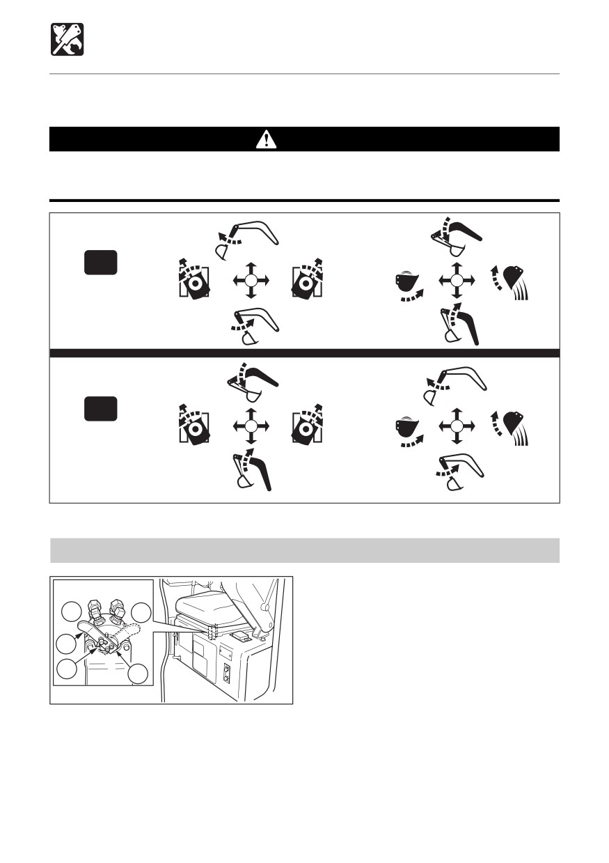
OPTIONS
Switching the Lever Pattern
The operating pattern of the left and right operating levers can be changed.
WARNING
Before starting the engine, check the selector to see which operating pattern the left
and right operating levers are set for.
A
ISO
G
JCB
C4L004
Switching the Lever Pattern
4. Tighten the wing bolt (2) and fasten the
lever (3) in place.
G
A
5. Close the maintenance cover and check
the lever pattern.
3
2
1
C4L003
(A) : ISO pattern
(G) : JCB pattern
1. Open the maintenance cover.
2. Loosen the wing bolt (2) from selector
valve (1).
3. Turn the lever (3) to switch the pattern.
185
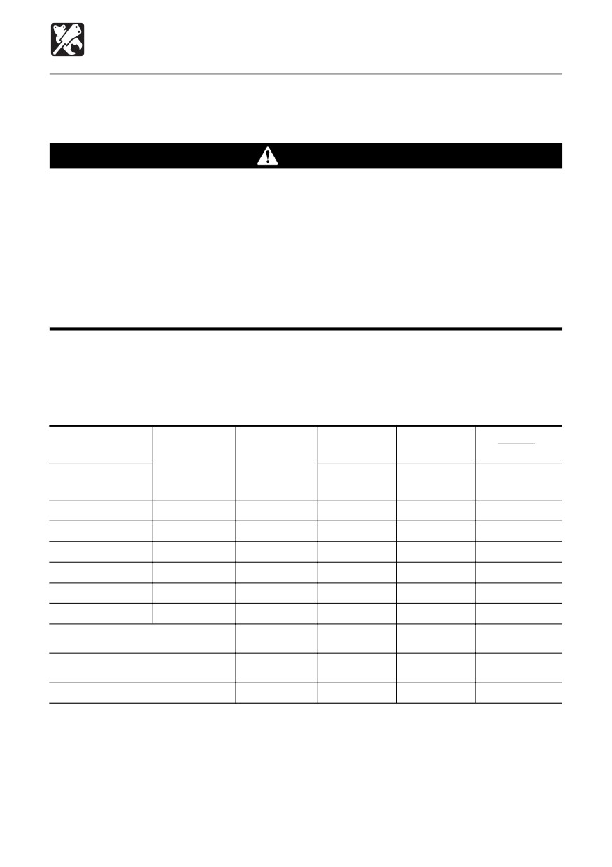
OPTIONS
Attachment Combination Table
Below is the bucket combination table for when arms and telescopic arms are installed. Heed
this table.
WARNING
¡ Consult with a Takeuchi dealer before installing optional attachments.
¡ Do not use attachments that have not been approved by Takeuchi or a Takeuchi
dealer. Doing so may compromise safety or adversely affect the machine’s operation
or service life.
¡ Takeuchi will not be held responsible for any injuries, accidents or damage to
products caused by the use of a non-approved attachment.
¡ Add an extra weight when using a long arm or a telescopic arm.
¡ Install a swing stopper when a bucket wider than the standard bucket, long arm and
telescopic arm is installed and when using a cab version.
✔ : Usable
∆ : Usable for light operations (digging and loading operations with dry, loose sand or mud)
— : Not usable
Total bucket weight = Weight of bucket + Weight of full bucket load (specific gravity : 1.8)
830 mm
1040 mm
TB014
Bucket cutting
Rated Capacity
(33 in.) Arm
(41 in.) Arm
width
m3 (cu.yd.)
Telescopic Arm
mm (inch)
930 mm
1130 mm
TB016
930 to 1380 mm
(37 in.) Arm
(44 in.) Arm
(37 to 54 in.)
260W Bucket
0.020
(0.026)
265 (10.4)
✔
✔
✔
300W Bucket
0.023
(0.030)
300 (11.8)
✔
✔
✔
350W Bucket
0.027
(0.035)
335 (13.2)
✔
✔
✔
450W (S.T.D.) Bucket
0.038
(0.049)
435 (17.1)
✔
✔
—
500W Bucket
0.043
(0.056)
485 (19.1)
✔
✔
—
Three-Hole Bucket
0.049
(0.064)
457 (18.0)
✔
✔
—
Total bucket weight = Within 98 kg
Within 485 (19.1)
✔
✔
✔
for Telescopic Arm
(216 lb.)
Total bucket weight = Within 127 kg
Within 485 (19.1)
✔
✔
—
(280 lb.)
Hydraulic Breaker (TKB-71)
✔
✔
—
186
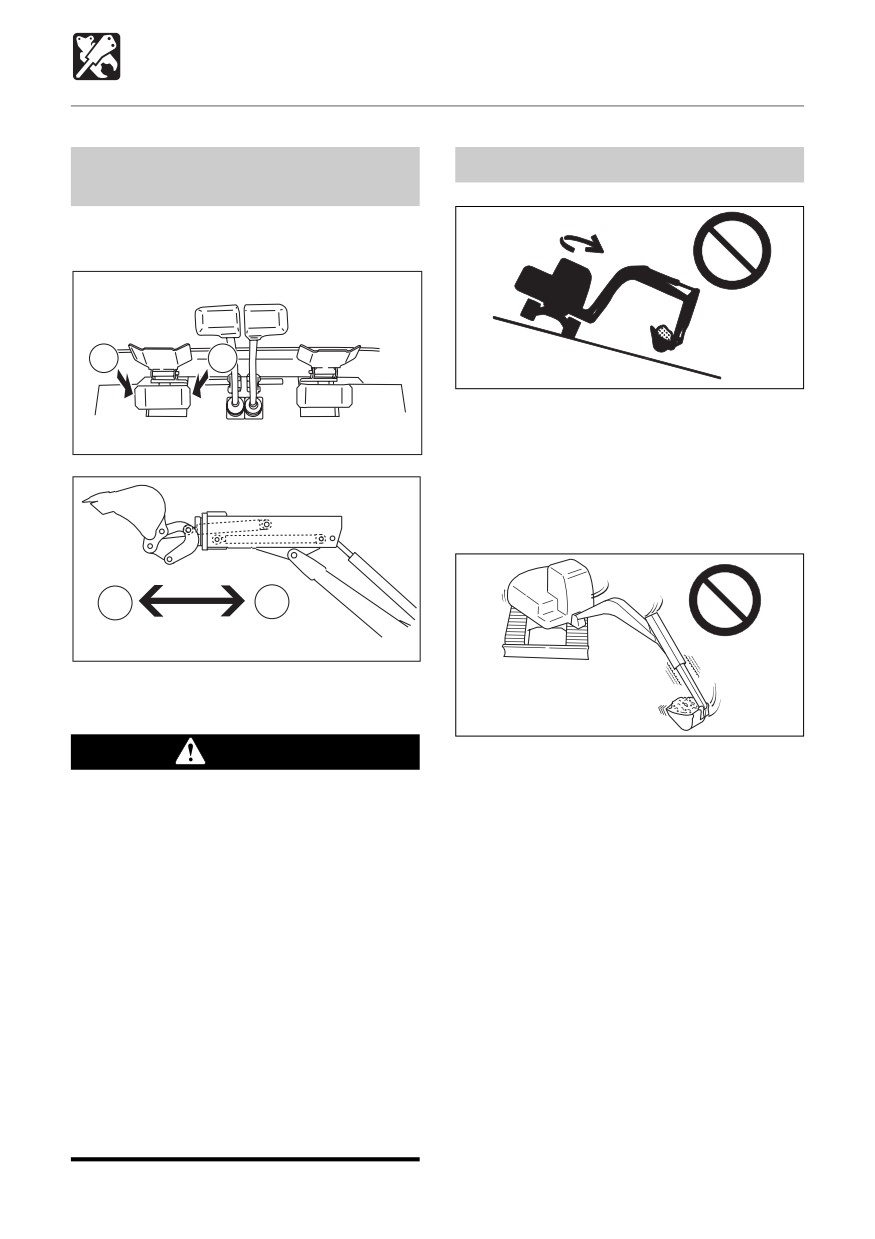
OPTIONS
Telescopic Arm
Extending and Retracting the
Caution on Using the Arm
Arm
Use the auxiliary pedal to extend and retract
the telescopic arm.
B
A
OE3A331
¡ The machine may loose balance and tip
over when slewing or operating the
C4B028
attachment on slopes. It is particularly
dangerous to slew with the arm extended
on the bucket full. Never do so.
B
A
C4L015
(A) Retract
(B) Extend
OL1L060
WARNING
¡ NEVER slew suddenly or stop slewing
suddenly with the arm extended. Doing
¡Excavator must be equipped with
so may damage the arm.
boom swing stopper.
¡Use caution when operating.
Telescopic arm reduces craning
capacity and bucket may come into
contact with excavator. Excavator may
become unstable when operating over
the side or with boom swing.
¡SAE heaped capacity of bucket
installed on telescopic arm must not
exceed 0.036 m3 (1.3 cu. ft.) .
¡Do not install hydraulic breaker,
compactor or similar attachment on
telescopic arm.
¡ Track-frame must be in wide position
when operating telescopic arm.
187
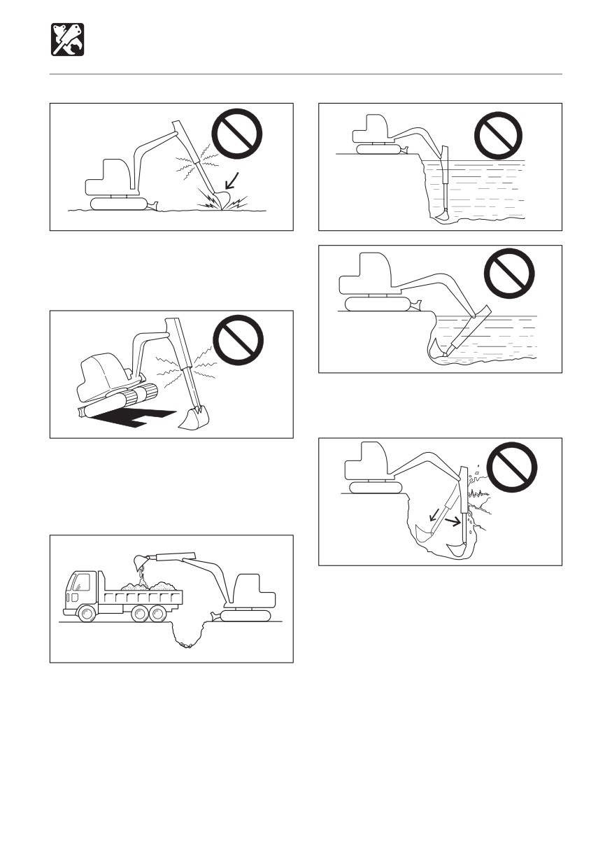
OPTIONS
Telescopic Arm
OL1L070
OL1L100
¡ Do not operate on base rock or hard soils,
as doing so may shorten the arm’s service
life.
OL1L110
¡ Do not put the arm under water. Also avoid
moisture when storing.
OL1L080
¡ Do not change directions with machine
lifted by pressing the bucket pressed
against the ground. Doing so may damage
the arm.
OL1L120
¡ The arm pressing speed is slow when
pressing the arm while simultaneously
extending it, but the arm pressing speed
suddenly comes faster when the arm
OL1L090
extending operation is stopped or the
cylinder end is reached. Be careful not to
¡ When dumping soil from the bucket or
hit surrounding objects.
shaking the bucket to remove the
remaining soil, do so with the arm retracted
to protect the arm extension/retraction
section.
188
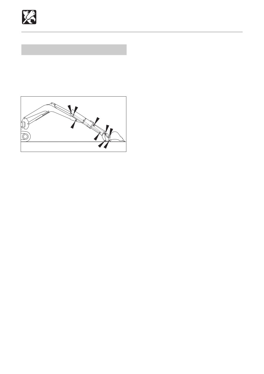
OPTIONS
Telescopic Arm
Inspection and Maintenance
Greasing
¡ Every day or every 10 hours
¡ Type of grease
Lithium-based multi-
purpose grease No. 2
¡ Greasing points
C4L014
1. Fully retract the bucket, arm and extend
the telescopic cylinders, lower the boom
and ground the bucket.
2. Lower the blade and stop the engine.
3. Clean the grease nipple.
4. Add grease to the grease nipple using a
grease gun.
5. Wipe off the grease that has been
squeezed out and any extra grease.
Looseness in the telescopic arm
When the telescopic arm is used for long
periods of time, wear of the sliding parts may
cause the gap between the outside arm and
inside arm to increase to above the set value,
resulting in looseness.
Other parts may be damaged if the telescopic
arm is used with such looseness. Contact a
Takeuchi dealer for maintenance.
Note that no maintenance is necessary other
than the greasing described above.
189
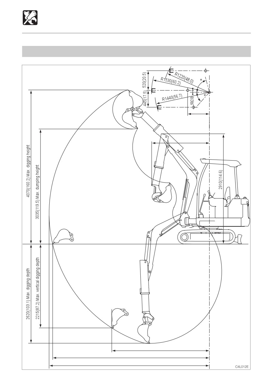
OPTIONS
Telescopic Arm
Operating Ranges TB016 Canopy (Fully Extended Arm)
Values are indicated in units of mm, inches in( ).
75
Bucket offset
50
575
(22.6)
Front slewing radius
1525(60.0)
2580(101.6)
4140(163.0) Max. ground digging radius
4230(166.5) Max. digging radius
190
OPTIONS
Telescopic Arm
Operating Ranges TB016 Canopy (Fully Retracted Arm)
Values are indicated in units of mm, inches in( ).
75
Bucket offset
50
575
(22.6)
Front slewing radius
1465(57.7)
2735(107.7) in Transport position
2490(98.0)
3705(145.9) Max. ground digging radius
3810(150.0) Max. digging radius
191
OPTIONS
Hydraulic Breaker
For handling of the breaker, read the
Precautions on Operating
hydraulic breaker’s manual, provided
separately.
< TB016 >
Do not use a breaker with the crawler
width narrowed!
WARNING
¡ When operating the machine, always
D5L005
set the crawler width to 1300 mm (51
¡ Run the engine with 75% the maximum
in.) for a more stable posture.
speed.
Operating with the crawler width
narrowed (980 mm (39 in.)) makes the
machine unstable and may cause it to
tip over.
Pressing force
¡ If you must operate with the crawler
width narrowed (980 mm), fold in the
hoe attachment, and lower the boom
to lower the center of gravity, and set
the machine facing directly forward
before traveling.
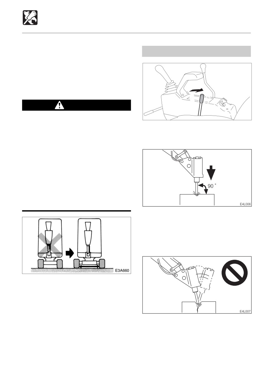
¡ Pound with the chisel perpendicular to the
surface you are pounding.
¡ When pounding, press the chisel properly
against the object to be broken so as to
avoid pounding the air.
When operating such optional attachments
as a breaker, tilted bucket or clamshell,
always set the crawler width to 1300 mm (51
in.) before operating.
IMPORTANT: When mounting devices,
¡ Do not pry with the chisel, and do not pry
select devices suited for this machine.
while pounding.
For advice on selecting device, contact a
¡ Do not move the chisel while pounding.
Takeuchi sales or service outlet.
¡ Do not pound continuously for over 30
seconds on the same surface.
192
OPTIONS
Hydraulic Breaker
Replace the hydraulic oil
regularly!
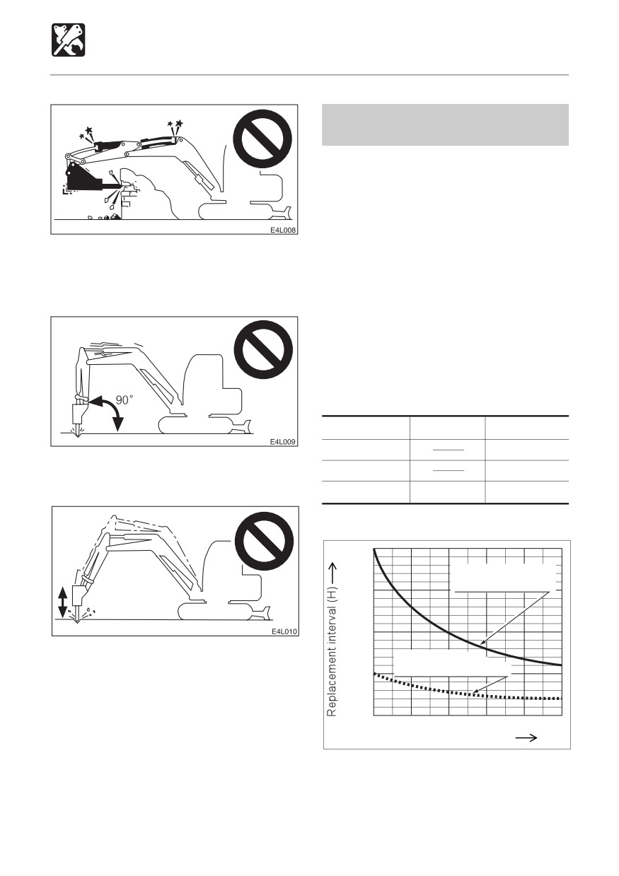
¡ When using a hydraulic breaker, the oil
deteriorates quicker than during normal
digging. Be sure to replace the hydraulic
oil and return filter element.
• Failure to replace these in time can lead
to damage to the machine and breaker’s
¡Do not pound with the cylinder fully
hydraulic systems. In order to improve
extended or contracted (at the stroke end).
the service life of the hydraulic systems,
Leave a margin of at least 5 cm.
be sure to replace the hydraulic oil and
return filter element according to the
following chart of the replacement
interval.
• Clean the suction strainer when
changing the return filter element.
Replacement Interval (Hours)
Item
Hydraulic Oil
Filter Element
1st time
25
¡ Do not pound with the arm perpendicular
2nd time
100
to the ground surface.
Periodically
600
200
When the breaker operating ratio is 100%
2000
Replacement interval
for hydraulic oil
1500
1000
¡ Do not drop the breaker itself on the object
Replacement
interval for filter element
to be broken in order to break it.
500
¡ Do not move objects to be broken or rocks
with the breaker itself.
¡ Slew occasionally to cool the engine.
0
20
40
60
80
100
¡ If a hydraulic hose is vibrating abnormally,
Breaker operating ratio (%)
N0G036
nitrogen gas may be leaking from the
accumulator. Have an inspection as soon
as possible.
193
OPTIONS
Three-Hole Bucket
A B
Replacing the Bucket Teeth
Replace the bucket teeth when the tooth
points are worn, before the adapter is
damaged.
WARNING
OL1L170
¡Before performing maintenance or
repairs under the machine, set all
working equipment against the ground
or in the lowermost position.
¡ To prevent unexpected movement,
securely block the working elements
when repairing or replacing the bucket
teeth.
OL1L180
¡ Wear required appropriate equipment
such as safety glasses when using
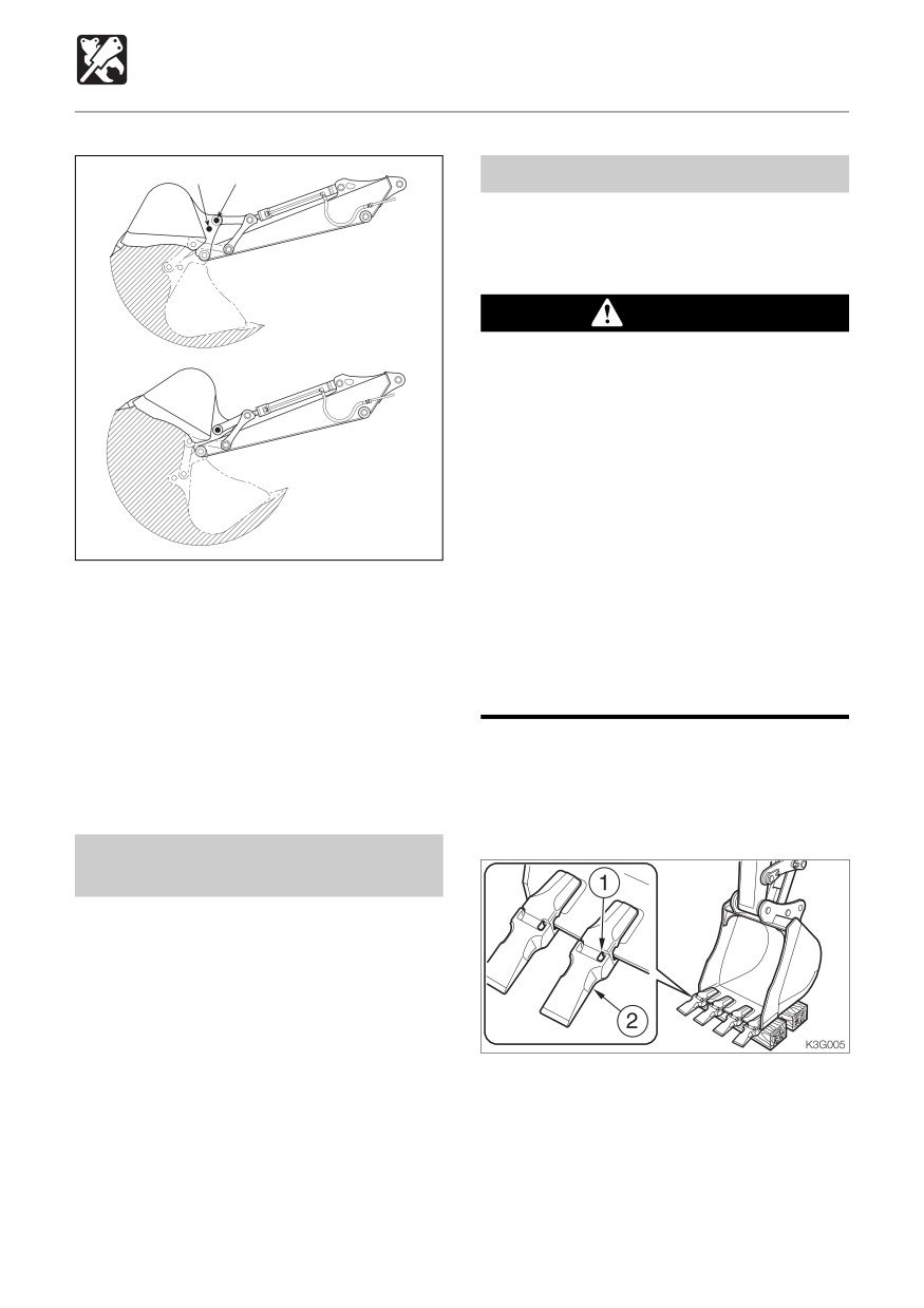
The digging capacity increases when the
hammers, as metal fragments or other
bucket’s link arm installation position is
objects can fly and cause serious
switched from (A) to (B). However, this
personal injury.
shortens the bucket stroke.
¡ Do not allow unauthorized personnel
• Struck capacity (SAE):
in the work area.
0.038 m3 (0.049 cu. yd.)
• Rated capacity (SAE):
0.049 m3 (0.064 cu. yd.)
Removal
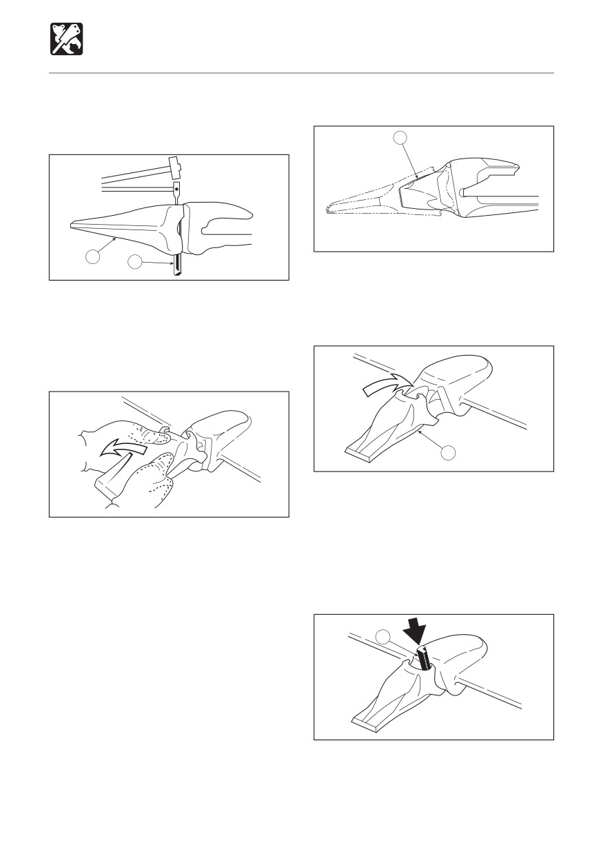
1. Clean the bucket and park the machine in
a flat, safe place where the ground is hard.
Changing the Link Arm
Installation Position
Refer to “Replacing the Bucket” in the
manual.
2. Set the bottom surface of the bucket flat
and lower it on a block so that the locking
pin (1) can be knocked out.
194
OPTIONS
Three-Hole Bucket
3. Remove the key, then check that the
Installation
bucket is stable.
3
OL1L220
2
1
1. Clean the adapter nose (3).
OL1L200
If there is gravel or mud on the adapter
4. Place a rod against the locking pin (1) and
nose, the tooth point will not go in all the
knock the locking pin out by hammering
way and the pin cannot be driven in.
against the rod.
The rod should be round and thinner than
the locking pin.
2
OL1L230
2. Put the tooth point (2) in the adapter nose
OL1L210
(3).
Push in firmly until the tooth point (2)
5. Remove the tooth point (2).
touches the tip of the adapter nose (3).
Some tooth points (2) are of the type that
Some tooth points (2) are of the type that
are removed by turning (twisting) them
are installed by turning (twisting) them
counterclockwise.
clockwise.
The same procedure can be used to
remove the other tooth points.
1
OL1L240
3. Insert the locking pin (1), making sure it is
in the right direction.
195
OPTIONS
Three-Hole Bucket
1
2
OL1L250
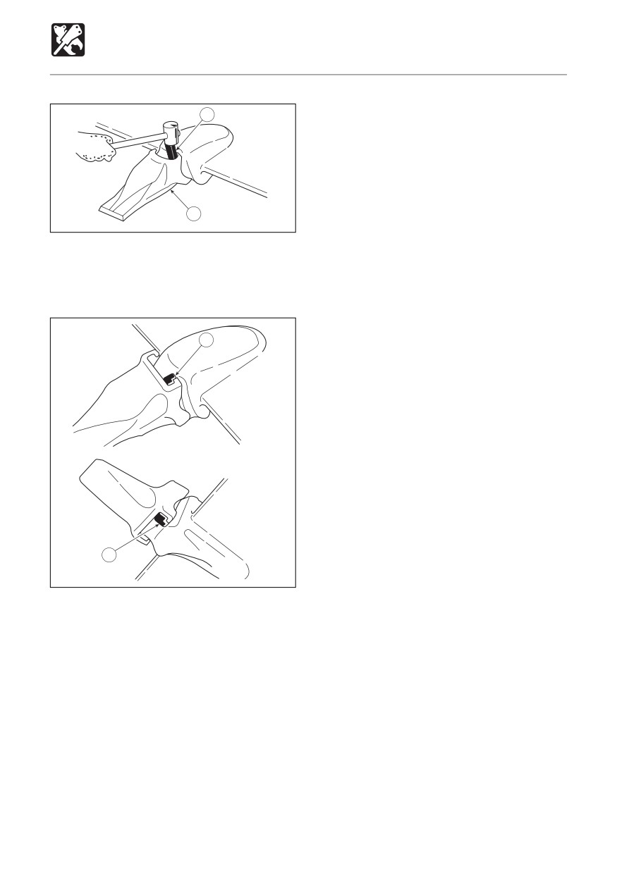
4. Drive in the locking pin (1) with a hammer
until it is flush with the tip of the tooth point
(2) ear.
1
OL1L260
1
OL1L270
5. The locking pin (1) is now driven in.
The same procedure can be used to install
the other tooth points.
196
OPTIONS
High-back Seat
Seat
3
WARNING
Adjust, secure and latch the operator’s
seat.
130kg
50kg(110 lbs.)
(287 lbs.)
C
C4L017
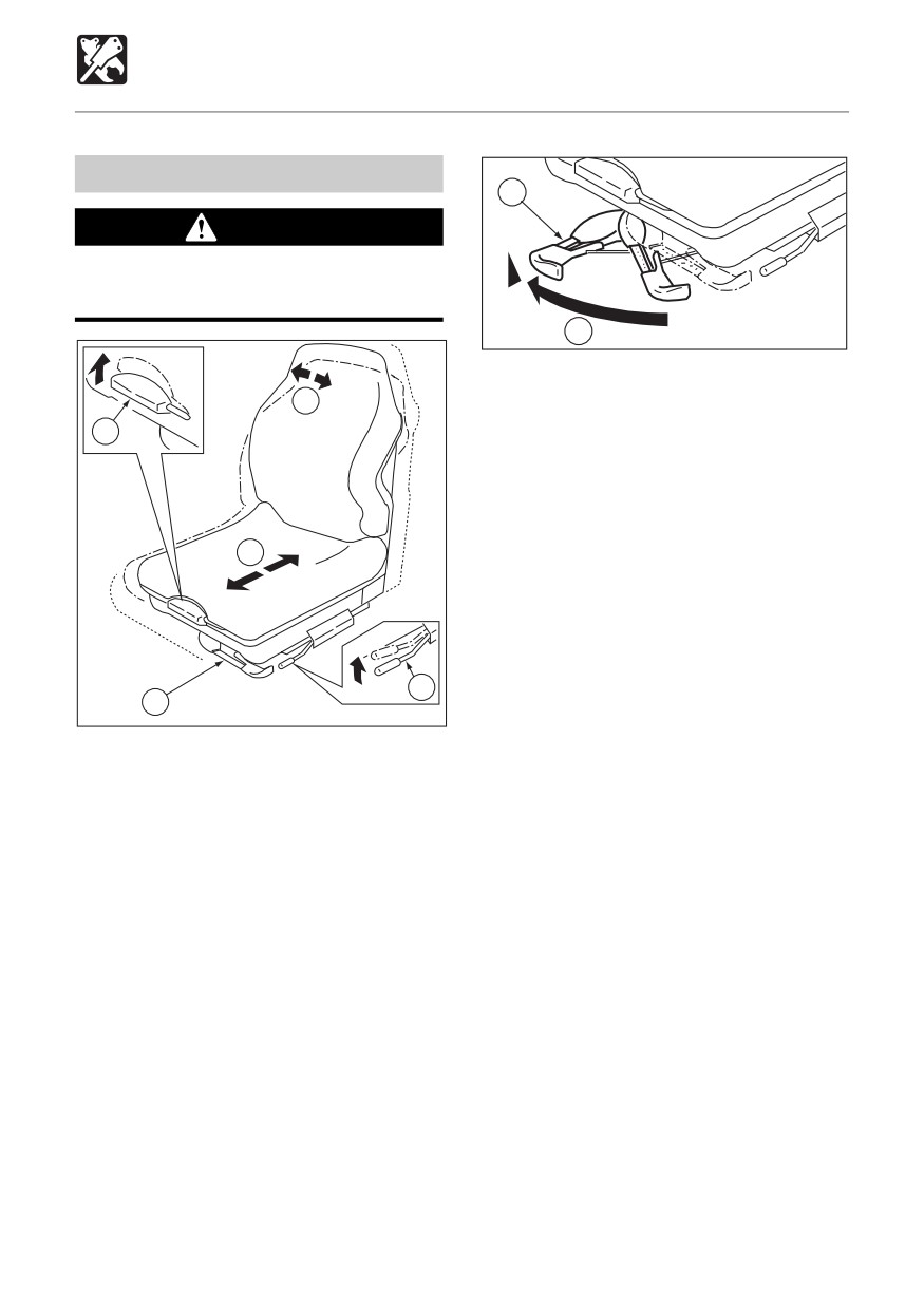
(C) Weight adjustment
A
1. Turn handle (3) to the front side and set it
1
to indicate the weight of the person to
operate the machine.
May be set to any value from 10 kg (22
lbs.) steps, 50 to 130 kg (110 to 287 lbs.).
2. When adjusting for a weight lower than
B
the currently set weight, first turn handle
(3) as far as it goes to cancel the setting,
then readjust.
2
3
C4L016
(A) Back angle adjustment
1. Raising your torso, sitting down firmly in
the seat.
2. Pulling lever (1) allows you to use the
pressure of the springs in the seat pressing
against your back to adjust the reclining
angle of the seat back. Release the lever
(1) at the desired angle and the seat back
will be locked in that position.
(B) Fore-and-aft adjustment
1. Pull on lever (2) and slide the seat
backward or forward to bring it to the
optimum position for operating the
machine.
2. Release the lever (2) at the desired
position and the seat will be locked there.
Adjustment stroke: 10 steps,
150 mm (5.9 in.)
197
OPTIONS
High-back Seat
Seat Belt
CAUTION
Always fasten the seat belt securely
before starting the engine.
Fastening the seat belt
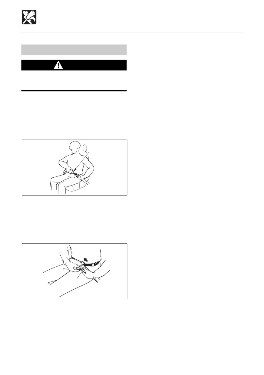
1. Adjust the seat to the optimum position
for operating, raise your torso, and sit back
firmly into the seat.
2. Pull the seat belt to the desired length.
A
B
E4B023
3. Make sure that the belt is not twisted and
then insert the tongue plate (A) into the
buckle (B) of the seat belt until you hear a
clicking sound as it locks in place.
Releasing the seat belt
C
E4B024
1. To remove the seat belt, simply press the
button (C) located on the buckle.
The seat belt is automatically stowed
away.
198
OPTIONS
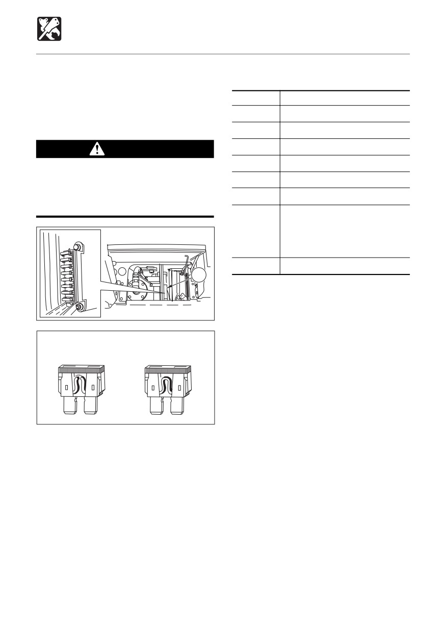
Travel Alarm
An alarm is sounded when the machine
Fuse Layout and Circuits Protected
travels and stops when traveling is stopped.
Capacity
Protected circuit
If the alarm does not sound when the
machine travels, the fuse may be blown.
30A
Stop solenoid
Inspect the fuse.
10A
Lever lock
10A
Second travel speed
WARNING
20A
Lights, Tail lamp
If the fuse which has just been replaced
should blow again, there is a problem in
15A
Heater, Radio
the electrical system. This could cause
10A
Feed pump, Instrument panel
fires. Contact a Takeuchi dealer.
25A
External power socket,
Cigarette lighter,
Wiper (cab),
Travel alarm
10A
Horn, Clock(radio), Interior light
1
C4B029
Blown
Normal
E4J007
1. Park the machine in a safe place.
2. Set the starter switch to “OFF”.
3. Open the fuse holder and inspect for blown
fuses.
4. If a fuse is blown, replace it with a spare
fuse of the same capacity.
199
OPTIONS
Radio (for EU)
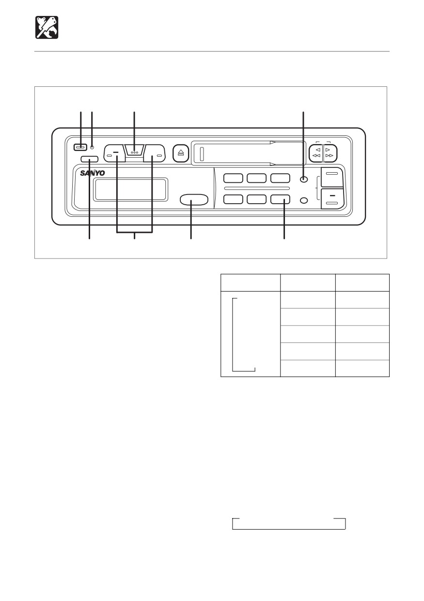
General operation
12
3
7
ON/OFF
AUDIO CONTEOL
DIR
SEL
LOUD
HI-POWER 35Wx4 / AUTO RADIO ACCESS
ATP
1
2
3
TUNE/SEEK
ʔP.SCAN
CLOCK
BAND
4
5
6
ELECTRONIC AUDIO CONTROL
FXC-315
5
4
6
8
C4C030
Turning the power on
MODE
- (Min)
+ (Max)
Press the ON/OFF button 1.
→
VOL
Down
0
Up
50
↓
Turning the power off
1, 2
BAS
Down
-5
Up
+5
Press the ON/OFF button 1 to stop current
↓
TRE
operation.
Down
-5
Up
+5
↓
The LED 2 lights when the ACC is on.
BAL
Left
L9
Right R9
↓
FAD
Electronic controls
3, 4
Front F9
Rear R9
Press the SEL button 3 to select the audio
functions as shown in the table below.
Loudness (LOUD) button
5
To adjust the volume, press the AUDIO
Press the LOUD button 5 to enhance the
CONTROL button 4 while in the volume
low-frequency sound at all volume levels.
mode.
When the LOUDNESS is on, on is displayed
To adjust the bass, treble, balance or fader,
for 3 seconds. Press the LOUD button again
press the SEL button to select the desired
to turn the LOUDNESS off and oFF is
operation, then press the - or + side of the
displayed for 3 seconds.
AUDIO CONTROL button.
Supplement: While no other mode is
Radio selection button (BAND)
6
displayed, the AUDIO CONTROL button
Each time the button is pressed, the function
functions as a volume control.
changes as shown below.
→ FM1 → FM2 → MW
200