Takeuchi Hydraulic Excavator TB175W (No. 175400095~). Operator's Manual - page 6
OPTIONS
Air Conditioner
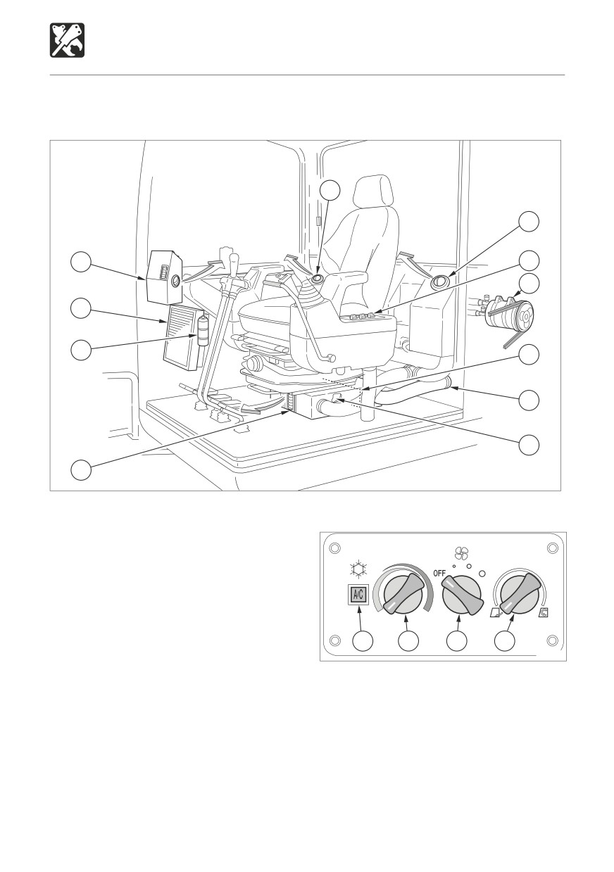
NAMES OF COMPONENTS
5
5
1
6
7
2
3
10
9
8
4
W3T010
1. Defroster
Control Panel
2. Condenser
3. Receiver drier
4. Foot outlets
5. Back outlets
6. Control panel
7. Compressor
8. Air conditioner unit
9. External air duct
11
12
13
14
10. Filter
L3T0021
11. Air conditioner switch
12. Temperature control dial
13. Fan switch
14. Airflow mode control dial
201
OPTIONS
Air Conditioner
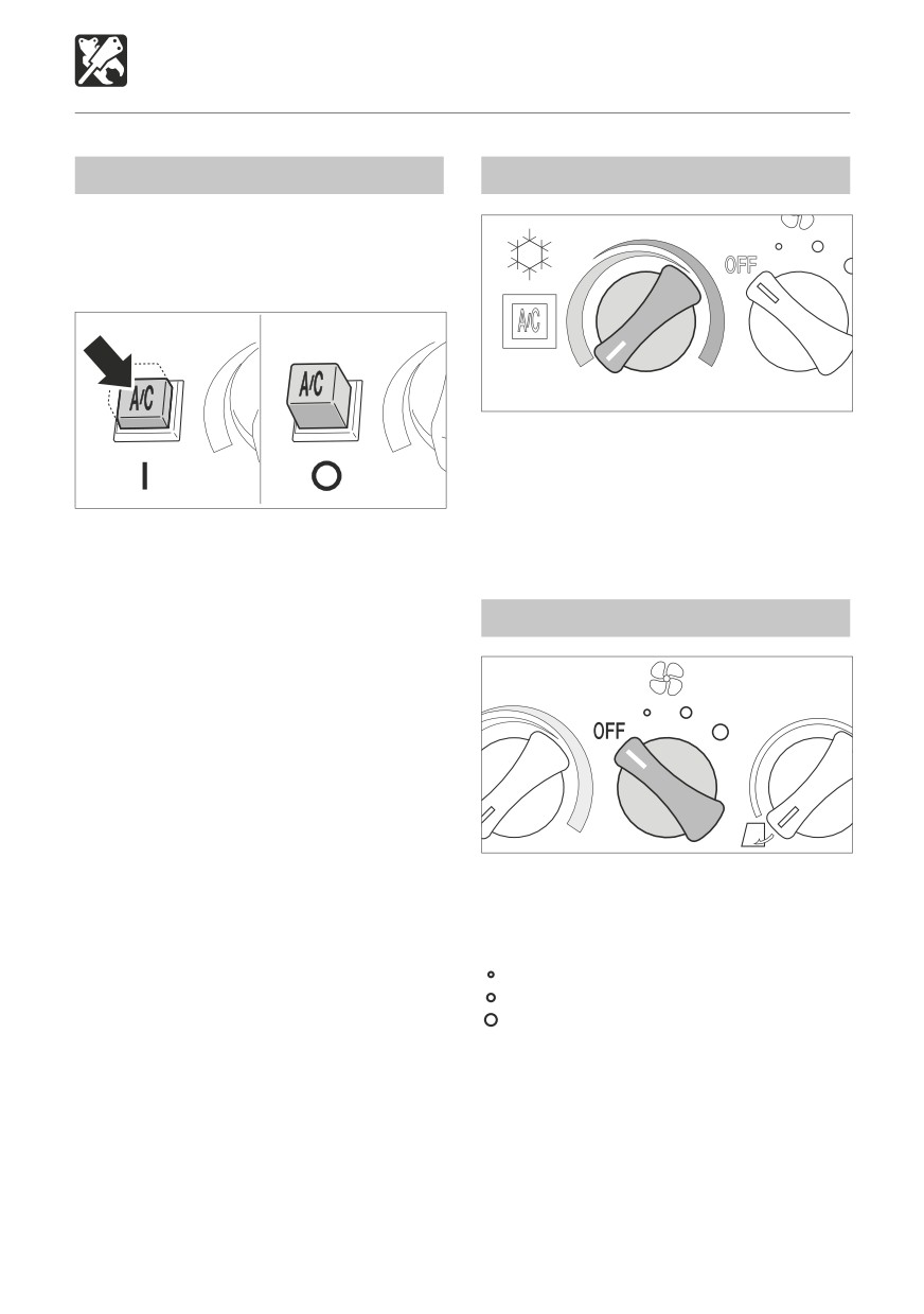
Air Conditioner Switch
Temperature Control Dial
IMPORTANT: To avoid placing an excessive
load on the compressor, wait until the
engine is started and is running smoothly
before turning on the air conditioner.
COOL
WARM
L3T005
Use this dial to adjust the air temperature.
COOL
To lower the temperature
WARM
To increase the temperature
L3T006
Supplement: No warm air is emitted if the
Use this switch to turn the air conditioner ON
temperature of the engine coolant is low.
and OFF. When this switch is pressed while
the engine is running and the fan switch is ON,
the air conditioner turns on. Press the switch
Fan Switch
again or turn the fan switch OFF to stop the
air conditioner.
O
OFF
I
ON
Supplement: To prevent leakage of coolant
gas from the compressor’s seal, operate
the air conditioner at least once a week,
regardless of the season.
Supplement: The air conditioner will not
function if the temperature in the cab is low
L3T003
(about 3°C (38°F) or lower).
Use this switch to adjust the fan speed in
three steps. At the OFF position, the air
conditioner is also OFF.
OFF
Fan and air conditioner off
............... Low
............... Medium
.............. High
202
OPTIONS
Air Conditioner
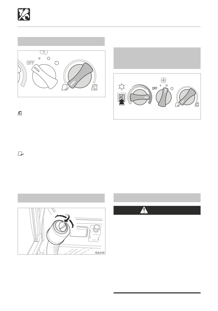
Airflow Mode Control Dial
OPERATION
Heating and Dehumidifying
(in cold weather or when the
humidity is high)
L3T004
Use this dial to select recirculation or fresh
air intake.
.................. Recirculation
L3T008
• To cool or heat the cab quickly
• When external air is dirty
After starting the engine, turn the air
CENTER
50% fresh air intake
conditioner ON and adjust the switches as
• To let in fresh air
shown in the diagram above.
• To ventilate while cooling or heating the
The outflow slot of foot area and the outflow
cab slowly
slots of the defroster can be directed at the
................ Fresh air intake
front window.
• To let in fresh air
Warm, dehumidified air blows on the front
• To remove fog from the windows
window, preventing fogging.
• To ventilate while cooling or heating the
Set the temperature control dial and fan
cab
switch to the desired positions.
Outlets
Cooling
CAUTION
When the air conditioner is set to the
recirculation mode, the air in the cab
gradually becomes dirty, so switch
to external air to ventilate once a
comfortable temperature is reached.
Excessive cooling can be harmful to
your health. It is best to keep the air
Move the louvers up and down or left and
inside the cab only about 5 to 6°C (41
right to adjust the air flow direction and
to 43°F) cooler than the outside air.
amount.
If the excavator has been parked in the
sun, open the windows or door to let the
hot air out of the cab before using the
air conditioner.
203
OPTIONS
Air Conditioner
Defogging the Windows
CAUTION
If the air conditioner is set to high when
using the defroster, the difference between
the external and internal temperatures
increases, and fog may form on the
L3T009
outside of the windows. If this happens,
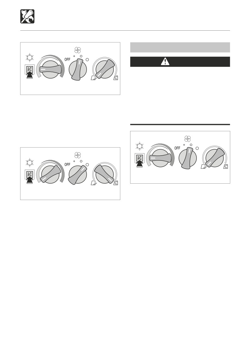
After starting the engine, turn the air
either turn the air conditioner OFF or turn
conditioner ON and adjust the switches as
the temperature control dial clockwise
shown in the diagram above.
(WARM).
Set the temperature control dial and fan
switch to the desired positions.
Quick cooling
L3T009
After starting the engine, turn the air
L3T010
conditioner ON and adjust the switches as
shown in the diagram above.
To cool the cab quickly, set the airflow mode
The outflow slot of foot area and the outflow
control dial to the recirculation position and
slots of the defroster can be directed at the
the fan switch to High, as shown on the
front window.
diagram above.
204
OPTIONS
Air Conditioner
Inspection
INSPECTION AND MAINTENANCE
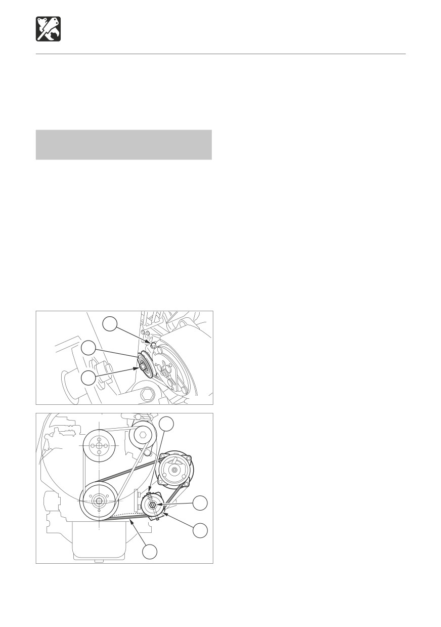
1. Open the bonnet.
Inspection and maintenance interval
2. Press on the center of the belt (1) with
............................ Every 250 hours
a finger. The belt’s tension is normal if it
bends about 8 mm (0.3 in) when pressed
Inspecting and Adjusting the Air
with a force of about 98N (22 lbf.).
Conditioner Belt
Adjustment
Inspection and maintenance interval
If the belt’s tension is not normal, adjust it with
...... After first 50 hours (New machines only)
the adjust bolt (3).
IMPORTANT: Do not let any oil or grease
1. Loosen the nut (4).
get on the belt, as it will cause the belt to
2. Tighten the bolt (3) to decrease the
slip, shortening its service life and reducing
tension.
the air conditioner’s cooling capacity.
Loosen the bolt (3) to increase the
If the belt is slack, it will slip and vibrate,
tension.
shortening its service life and reducing the
3. After adjusting is completed, tighten the
air conditioner’s cooling capacity. The belt
nut (4).
should also not be too tense. Adjust the belt
tension to the standard value (approximately
Replace
8 mm or 0.3 in).
Replace the belt in the following cases:
• If it stretches and its tension cannot be
3
adjusted.
• If it is cut or cracked.
2
• If the fan belt is worn and the pulley is
touching the bottom of the V groove.
4
W3T020
3
4
2
1
L3T012
205
OPTIONS
Air Conditioner
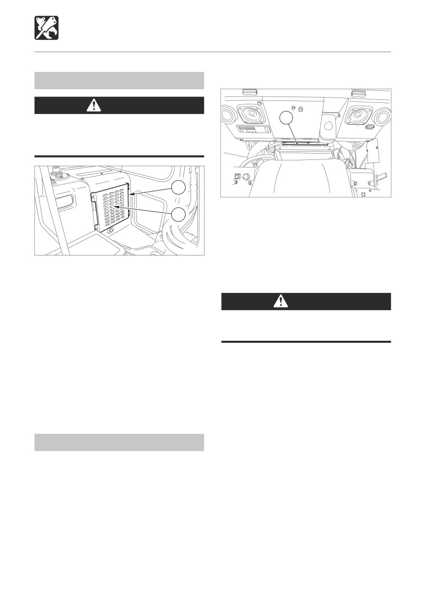
Removing the filter
Cleaning the Condenser
CAUTION
1
Cleaning the condenser with high
pressured water may damage it. Clean
the condenser gently.
1
L7T020
1. Move the seat all the way forward, then
2
fold down the seat back toward the front.
2. Remove the filter (1).
3. Use compressed air or water to clean the
L3T011
filters, depending on how dirty it is.
If the condenser is dirty, heat will not discharge
properly. Wash dirt off the condenser with
Cleaning
water.
1. Remove the cover (1) on the right side of
CAUTION
the cab.
Wear safety glasses when using
2. Clean the condenser (2).
compressed air.
1. Blow dry, compressed air (138 kPa or 20
psi or less) directly on the filter from the
inside, moving up and down along the
creases.
Be sure to keep the nozzle at an adequate
distance from the filter.
2. For tough dirt, wash the filter (1) with
neutral detergent and water. Dry the filter
Cleaning the Filter
(1) completely after washing it.
Clean the filter sooner when operating in
dusty places.
If the filter is clogged, the air becomes weak
and a muted booming sound is heard from
the air conditioner unit.
206
OPTIONS
Air Conditioner
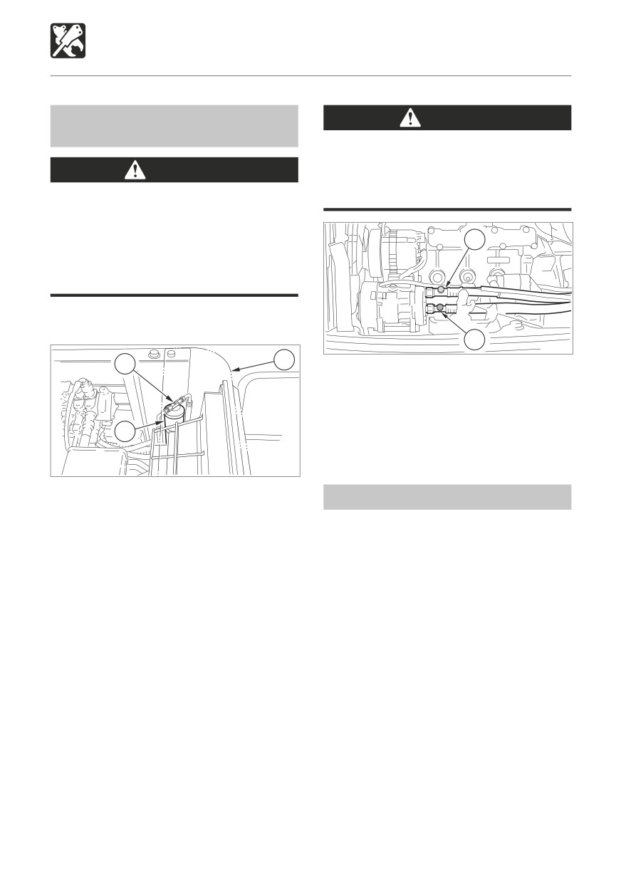
Inspecting the Refrigerant (gas)
CAUTION
Level
The high pressure pipe becomes hot (80
to 120°C (176 to 248°F)), so be careful
WARNING
not to burn yourself when inspecting the
refrigerant level.
Exposure of the eyes or hands to the
cooler’s refrigerant could result in blindness
or frostbite. Never touch the refrigerant or
2
loosen the parts of the cooling circuit.
Should the refrigerant gas leak, keep
flames away.
The cooling capacity will decrease if the
amount of refrigerant is insufficient.
1
L3T017
3
2
4. Also check the temperature of the
compressor’s high pressure pipe (1) and
low pressure pipe (2). Refer to page 208
“Condition of the refrigerant.”
1
L3T014
Inspect the refrigerant level using the sight
Off-Season Inspection
glass (2) on the top of the receiver drier (1).
1. Remove the center cover(3).
Even off season, run the cooler for 3 to 5
2. Inspect under the following conditions:
minutes at least once a week to maintain oil
• Cab door
Fully open
in the various parts of the compressor.
• Temperature control dial
.............................Fully to the COOL
side
• Air strength
High
• Airflow mode control dial
.............................Recirculation position
• Engine speed
Maximum speed
• Air conditioner
On
3. Inspect by watching the flow of air bubbles
in the refrigerant through the sight glass
(2). Refer to page 208 “Condition of the
refrigerant”.
207
OPTIONS
Air Conditioner
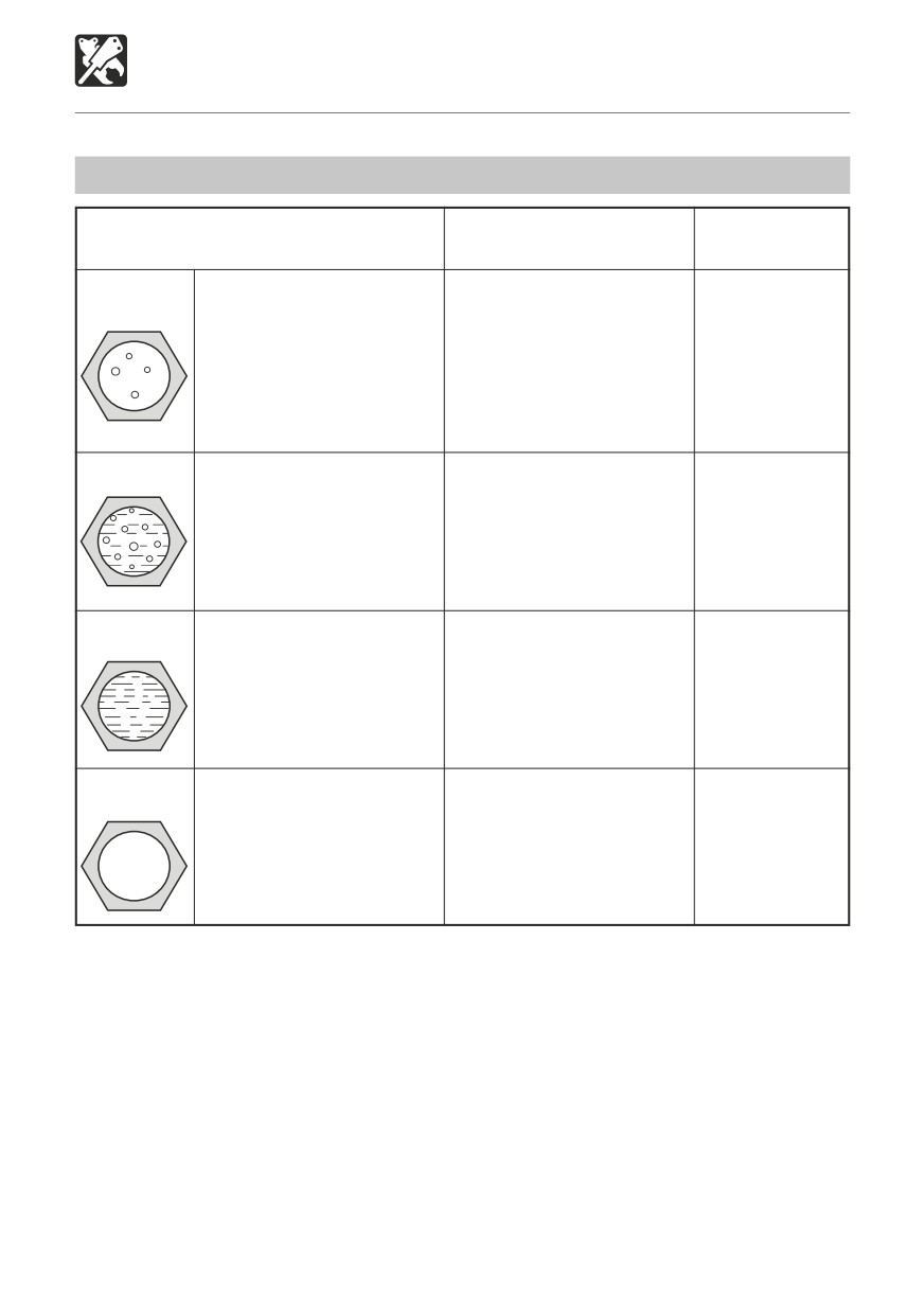
Condition of the refrigerant
High / low pressure pipe
Sight glass (refrigerant)
Pipe connection
temperature
Almost transparent, with
High pressure pipe (1) hot
No irregularities.
Normal
some bubbles, but fully
(80 to 120°C (176 to 248°F)),
transparent when the engine
low pressure pipe (2) cold
speed is increased or
(8 to 15°C (46 to 59°F)).
decreased.
Clear difference in
temperature between the
pipes.
Refrigerant
Flow of bubbles can be seen
High pressure pipe warm,
Some oily
low
constantly. Refrigerant is
low pressure pipe somewhat
places.
sometimes transparent or
cool. No great difference in
has white bubbles.
temperature between the
Refrigerant may be leaking.
pipes.
Almost no
Some mist-like refrigerant
Almost no difference in
Some heavily
refrigerant
can be barely seen flowing.
temperature between the high
oily places.
Refrigerant has leaked, and
and low pressure pipes.
almost none is left.
Excess
No bubbles can be seen,
High pressure pipe is
No irregularities.
refrigerant
even when the fan is set
hot, low pressure pipe is
to high and the engine is
somewhat cool.
idling.
There is a difference in
temperature between the
pipes.
If the air conditioner does not function
If the air conditioner does not cool or heat the air, set the fan switch to OFF and contact a
service outlet for inspection and/or repairs.
IMPORTANT: Continued use of the air conditioner when it is not functioning properly
may damage its various parts.
IMPORTANT: Using the air conditioner when there is no refrigerant will damage the
compressor. Be particularly careful not to do this.
IMPORTANT: Always have a service outlet add or replace the refrigerant. Be sure to use
R134a refrigerant (1700g or 3.75 lb).
208
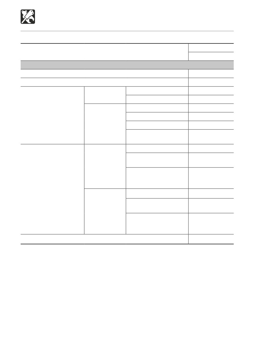
OPTIONS
Optional Equipment Mass
Standard machine mass kg (lb.)
Cab
(Not including operator)
7845 (17295)
OPTION
Undercarriage outriggers
445 (985)
2-Piece boom
300 (665)
Boom
10 (25)
Mono-boom
Arm
20 (45)
Boom
15 (35)
Emergency shut-off
Boom + Adjustment
30 (70)
valve
2-Piece boom
Boom + Arm
20 (45)
Boom+ Adjustment
40 (90)
+ Arm
Second aux.
20 (45)
Second aux.
30 (70)
+ Third aux.
Mono-boom
Second aux.
+ Third aux.
55 (125)
+ Fourth aux.
Auxiliary hydraulic lines
Second aux.
20 (45)
Second aux.
35 (80)
+ Third aux.
2-Piece boom
Second aux.
+ Third aux.
60 (135)
+ Fourth aux.
Air conditioner
60 (135)
Units: kg (lb.)
*: Mass of optional equipment is added to the standard machine mass.
*: This table only contains the optional equipment of 10kg (20lb.) or more in mass.
209
First Published February 2008
No. 40100
Fifth Published May 2012 OE-T175W-E
OPERATOR’S MANUAL
TB175W Hydraulic Excavator
Edited and issued by TAKEUCHI MFG. CO., LTD.
Printed in Japan by STATION M Co., Ltd.