Takeuchi Hydraulic Excavator TB175W (No. 175400095~). Operator's Manual - page 5
TROUBLESHOOTING
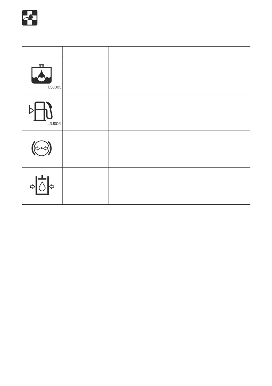
If a Warning Lamp Flashes
Warning lamp
Lamp name
Procedure
Water
Water has accumulated in the water separator. Drain
separator
the water.
warning lamp
Refer to page 148 “Draining the Water Separator”.
Fuel level
The fuel level is low. Supply fuel.
warning lamp
Refer to page 45 “Fuel Filler Cap”.
Brake oil
The brake fluid pressure is low.
pressure
Consult a Takeuchi sales or service outlet.
warning lamp
W2J003
Third auxiliary
Pressure in the third auxiliary hudraulic lines is low.
hydraulics
Consult a Takeuchi sales or service outlet.
warning lamp
W2J004
(option)
161
TROUBLESHOOTING
Other Symptoms
For symptoms not included on the table below or if the problem persists after the proper
procedures have been taken, consult a Takeuchi sales or service outlet.
Symptom
Main cause
Procedure
Left and right operating
Insufficient grease on left and
Add grease.
levers and boom swing
right operating levers and
Refer to page 151.
pedal do not move
boom swing pedal
smoothly
Steering operation not
Defective steering unit
Contact a sales or service
possible
outlet.
Hoe attachment,
Safety lock lever is locked
Release the safety lock
auxiliary hydraulics,
lever.
slewing or traveling
Fuse is blown
Refer to page 57.
operation not possible
Replace the fuse.
Refer to page 158.
Digging force is
Insufficient hydraulic oil level
Replenish to the prescribed
insufficient
level.
Refer to page 118.
Hydraulic oil is not heated
Perform the warm-up
procedure.
Refer to page 76.
Air cleaner is clogged
Clean the air cleaner.
Refer to page 131.
Hydraulic oil is not of suitable
Replace the hydraulic oil.
type
Refer to page 142.
Traveling is not possible
Stones or foreign objects are
Remove the foreign object.
or not smooth
stuck
Brake pedal is locked
Release the brake pedal.
Refer to page 59.
Parking brake is activated
Turn off the parking brake
switch.
Refer to page 51.
Release the safety lock
lever.
Refer to page 57.
Machine does not travel
Stones or foreign objects are
Remove the foreign object.
straight forward
stuck
Air pressure in tires is uneven
Make the air pressure in the
different tires uniform
Slew speed cannot be
Fuse is blown
Replace the fuse.
shifted
Refer to page 158.
162

TROUBLESHOOTING
Other Symptoms
Symptom
Main cause
Procedure
Travel speed cannot be
Fuse is blown
Replace the fuse.
changed
Refer to page 158.
Slewing is not possible
Insufficient grease on slew
Add grease.
or not smooth
bearing
Refer to page 127.
Hydraulic oil
Insufficient hydraulic oil
Replenish to the prescribed
temperature is too high
level.
Refer to page 118.
Starter motor turns but
Insufficient fuel
Add fuel.
engine does not start
Refer to page 118.
Air in fuel system
Bleed the air.
Refer to page 157.
Water in fuel system
Drain the water.
Refer to page 148.
Engine exhaust is white
Excessive engine oil
Adjust to the prescribed
or bluish
level.
Refer to page 117.
Poor fuel
Replace the fuel.
Engine exhaust is
Air cleaner is clogged
Clean the air cleaner.
occasionally black
Refer to page 131.
Irregular noise is
Low quality fuel is being
Replace the fuel.
produced from the
used
engine (combustion or
Engine is overheating
If the Engine Overheats
mechanical noise)
Refer to page 155.
Damage in muffler
Replace the muffler.
(Request at a sales or
service outlet.)
163
TROUBLESHOOTING
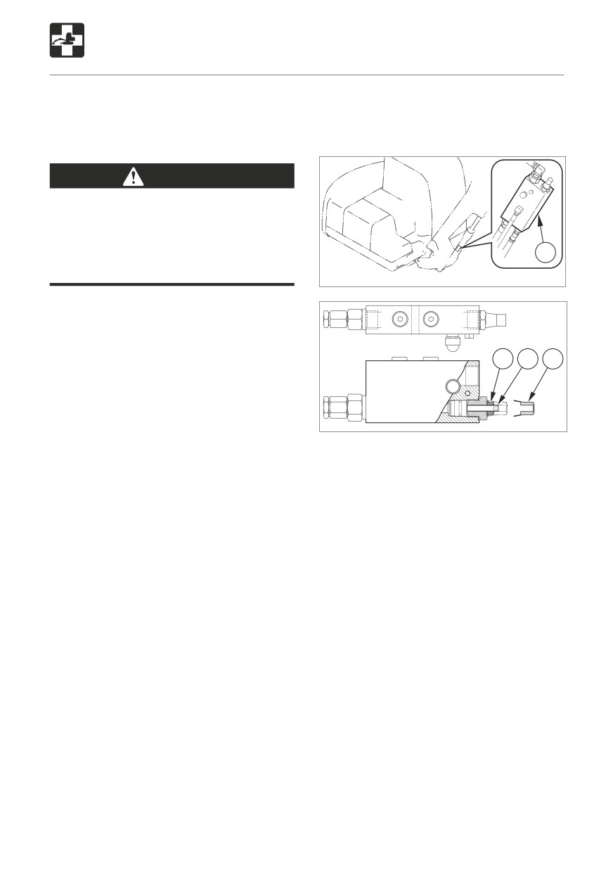
To Lower the Boom
If the hoe attachment must be lowered to the
Procedure 2
ground while the engine is stopped, use the
If equipped with emergency shut-off valve
following procedures to do so.
WARNING
Do not approach in the area of the
ground where the hoe attachment is to
be lowered. You may be hit by dirt falling
out of the bucket or the hoe attachment
1
as it drops.
W2L008
Procedure 1
Perform the following procedure within 10
minuites after the engine is stopped.
1. Turn the starter switch key to the ON
3
4
2
position.
2. Release the safety lock lever.
3. Lower the boom by the operating lever.
4. Check for safety and machine stability.
W2L009
1. Check for safety in the working area and for
stability of the machine and lifted load.
2. Remove the cap (2).
3. Loosen the lock nut (3).
4. Tighten the stem (4) to lower the boom.
5. Check for stability of the hoe attachment
and load.
6. Loosen the stem (4) secure it with the lock
nut (3).
164
TROUBLESHOOTING
Towing
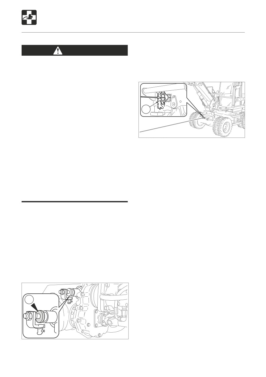
Knock plate (T) in the direction of the spring
WARNING
brake cylinder.
When towing, selecting the wrong wire
When next operated (releasing the parking
rope, inspecting improperly, or towing in
brake), the original position resumes.
the wrong way could lead to accidents
resulting in serious injury or death.
The wire rope breaking or coming
detached could be extremely dangerous.
Use a wire rope suited for the required
towing force.
1
Do not use a wire rope that is kinked,
twisted or otherwise damaged.
Do not apply strong loads abruptly to
W2A033
the wire rope.
Use safety gloves when handling the
Permissible forces:
wire rope.
25500 N (5730 lb) or less
Make sure there is an operator on the
machine being towed as well as on the
1. Attach the wire rope to the shackle (1).
machine that is towing.
2. Attach the wire rope to the object to be
Never tow on slopes.
towed.
Do not let anyone near the wire rope
3. Make the wire rope horizontal and line up
while towing.
straight with the travel frame.
4. Move the machine to tauten the wire
Towing the Machine
rope.
The machine is to be towed only when
5. Move the machine slowly and tow.
strictly necessary to remove it from danger.
In the interests of safety, towing operator is
reponsible for the following:
To ensure that a rigid towing rod and a
tow-truck with sufficient braking power are
used.
No servo-assisted steering - only manual
steering with great force.
T
W2E0151
Release the parking brake (if control oil
pressure fails):
165
166
SPECIFICATIONS
Main Specifications
168
Machine Dimensions
170
Operating Range
172
Lifting Capacities
177
167
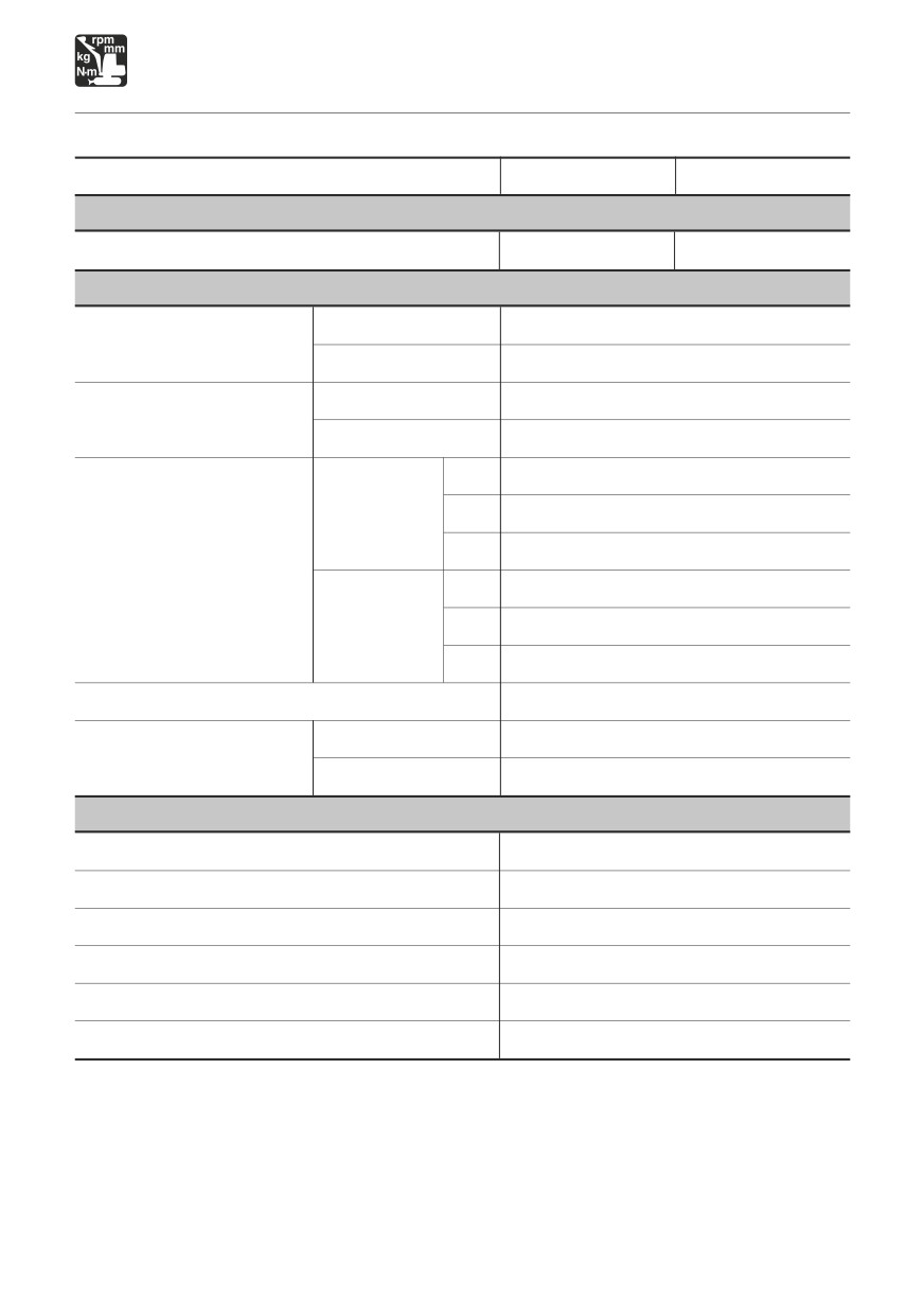
SPECIFICATIONS
Main Specifications
TYPE
2-Piece Boom
Mono-Boom
MASS
Machine mass kg (lb.) (not including operator)
8140 (17950)
7845 (17300)
PERFORMANCE
Heaped
0.245
(8.65)
Bucket capacity m3 (cu.ft.)
(standard bucket)
Struck
0.185
(6.53)
Slow speed
4.3 to 8.0 (4.3 to 8.0)*
Slew speed min-1
(rpm)
Normal speed
10.9
(10.9)
Creep
0 to 4.5 (0 to 2.8)
Forward
Site
0 to 9.0 (0 to 5.6)
Road
0 to 30 (0 to 18.6)
Travel speed km/h (mph)
Creep
0 to 4.5 (0 to 2.8)
Reverse
Site
0 to 9.0 (0 to 5.6)
Road
0 to 30 (0 to 18.6)
Gradeability (degrees)
35
Sound-power level
L WA 99
Noise level
dB(A)
Sound-pressure level
L pA 77
ENGINE
Manufacturer and model
Yanmar 4TNV98T-ZSTBW
Rated output
kW / min-1 (hp / rpm)
53.6 / 2200 (71.9 / 2200)
Displacement
mI (cu.in.)
3318 (202.5)
Starter
V - kW
12 - 3.0
Alternator
V - kW
12 - 0.96
Battery
V - A·h
12 - 90
*
: The maximum set speed in slow speed can be adjustable. Upon shipment, it is set to 8.0
min-1 (8.0 rpm).
168
MEMO
169
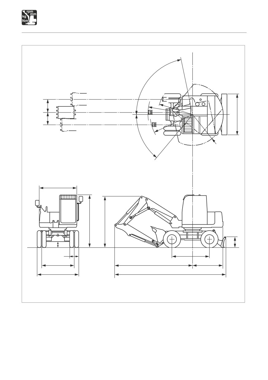
SPECIFICATIONS
Machine Dimensions
V
M
Q
L
H
P
N
W
D
B
C
U
S
K
J
F
R
T
E
G
A
W2K0011
170
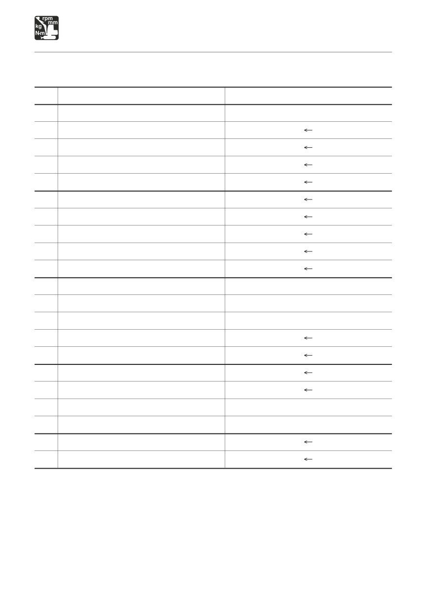
SPECIFICATIONS
Machine Dimensions
Units: mm (inches)
2-Peice Boom
Mono-Boom
A
6260 (246.4)
6320 (248.8)
B
2110 (83.1)
C
2925 (115.2) / 2970 (116.9) *
D
1720 (67.8)
E
1715 (67.5)
F
2100 (82.7)
G
2330 (91.7)
H
2300 (90.6)
J
515 (20.2)
K
335 (13.2)
L
2505 (98.6)
2620 (103.2)
M
1955 (77)
2060 (81.1)
N
2385 (93.8)
2495 (98.3)
P
690 (27.1)
Q
730 (28.8)
R
1815 (171.5)
S
600 (23.6)
T
4380 (172.5)
4445 (174.9)
U
2895 (114.1)
2645 (104.2)
V
80°
W
50°
* : When equipped with Roof guard.
171
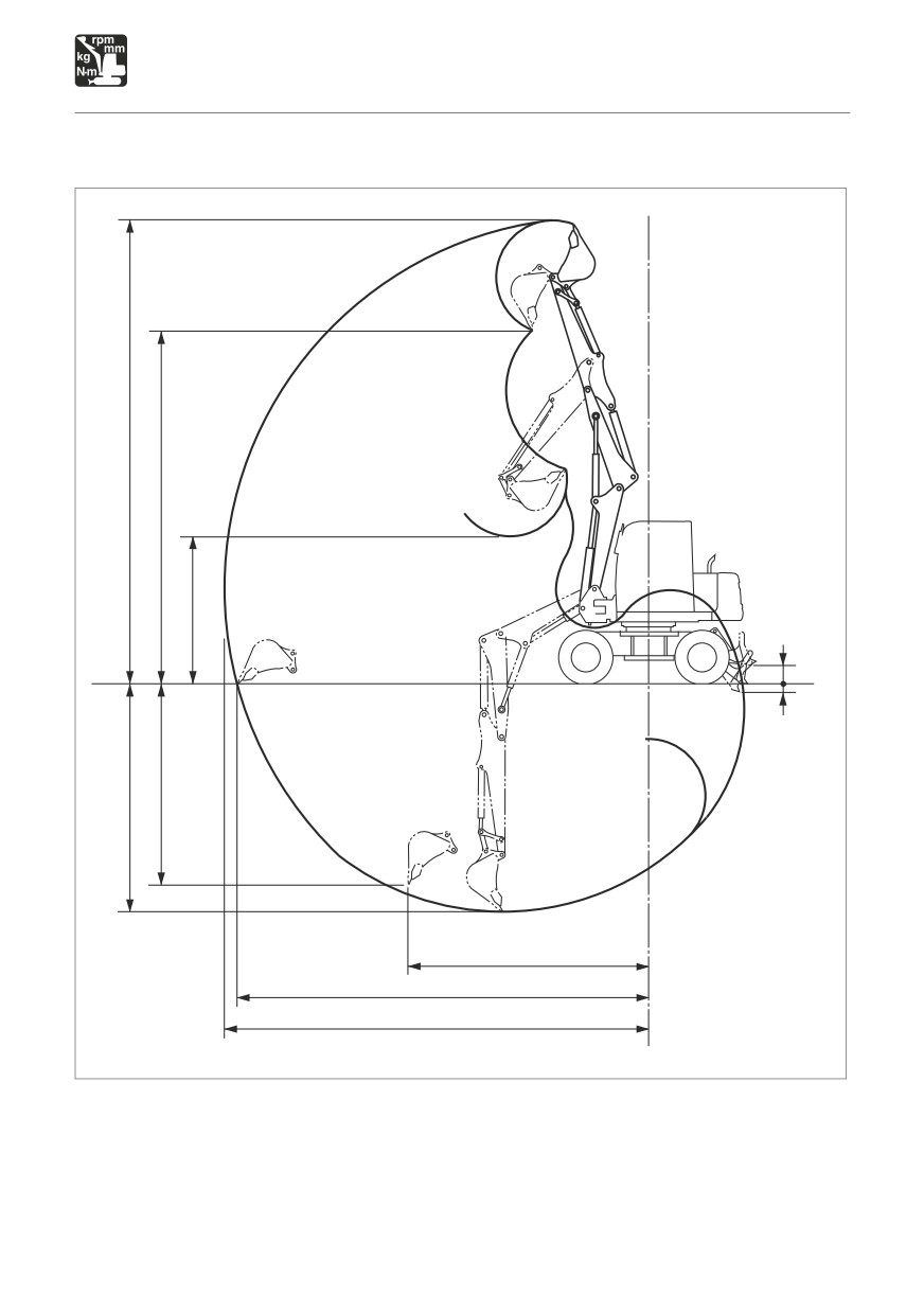
SPECIFICATIONS
Operating Range
2-Piece Boom
E
F
G
J
K
D
C
H
B
A
W2K002
172

SPECIFICATIONS
Operating Range
2-Piece Boom
Units: mm (inches)
A
Max. digging radius
7650 (301.2)
B
Max. ground digging radius
7430 (292.6)
C
Max. digging depth
4085 (160.8)
D
Max. vertical digging depth
3600 (141.7)
E
Max. digging height
8325 (327.8)
F
Max. dumping height
6355 (250.2)
G
Min. dumping height
2665 (104.9)
H
Max. vertical digging radius
4360 (171.6)
J
Max. raising height
335 (13.2)
K
Max. lowering depth
145 (5.7)
173
SPECIFICATIONS
Operating Range
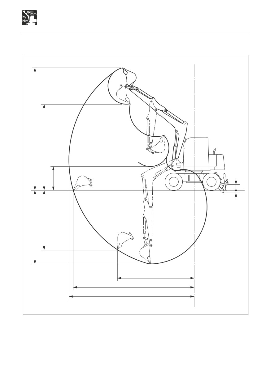
Mono-Boom
E
F
G
J
K
D
C
H
B
A
W2K003
174

SPECIFICATIONS
Operating Range
Mono-Boom
Units: mm (inches)
A
Max. digging radius
6945 (273.4)
B
Max. ground digging radius
6700 (263.7)
C
Max. digging depth
4055 (159.6)
D
Max. vertical digging depth
3220 (126.8)
E
Max. digging height
6780 (267)
F
Max. dumping height
4765 (187.7)
G
Min. dumping height
1330 (52.3)
H
Max. vertical digging radius
4270 (168)
J
Max. raising height
335 (13.2)
K
Max. lowering depth
145 (5.7)
175
MEMO
176
SPECIFICATIONS
Lifting Capacities
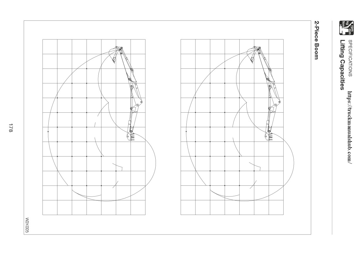
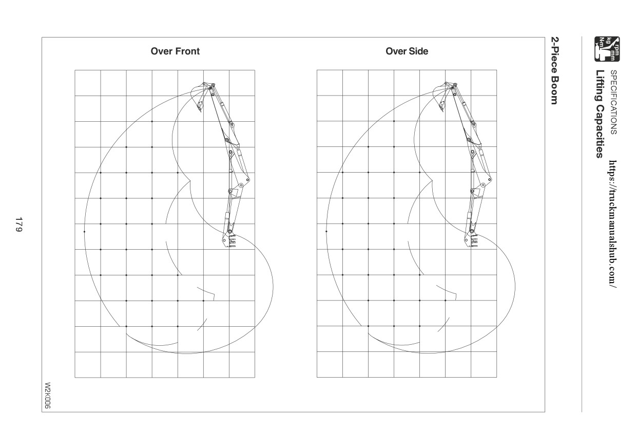
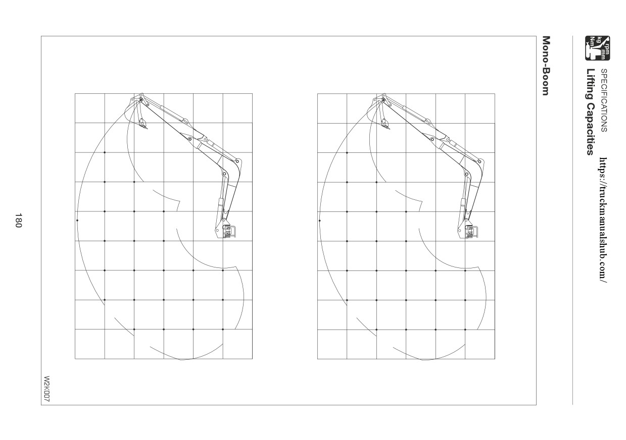
Rated lift capacity chart
The loads in the charts do not exceed 87% of hydraulic lift capacity or 75% of tipping
load.
Rated lift capacities limited by rated hydraulic lift capacity are identified by an asterisk(*)
The mass of slings and any auxiliary lifting devices shall be deducted from the rated load to
determine the net load that may be lifted.
The load point is the bucket hinge pin, and the bucket posture is with the standard bucket
completely retracted under the arm.
Units: daN (lbs.)
Load hooking system
A load hooking system with all of the following capacities must be provided and used.
1. A system which can withstand a weight of two times the rated lift capacity no matter at what
position the load is applied.
2. A system in which there is no risk of the lifted load falling from the hooking device, for example
one equipped with a hook slippage prevention device.
3. A system in which there is no risk of the hooking system slipping from the hoe
attachment.
Load safety device
In addition, the following load safety devices must be installed. (For details, contact a designated
service outlet.)
(1) An overload warning device.
(2) A boom lowering control device.
WARNING
DO NOT attempt to lift or hold any load that is greater than these rated values at their
specified load radii and height.
All rated lift capacities are based on the machine being level and on a firm supporting
surface. For safe working loads, the user is expected to make due allowance for the
particular job conditions such as soft or uneven ground, non-level condition, side
loads, hazardous conditions, experience of personnel, etc. The operator and other
personnel should fully acquaint themselves with the operator’s manual furnished
by the manufacturer before operating this machine, and rules for safe operation of
equipment shall be adhered to at all times.
Do not travel while lifting a load; It is very dangerous.
177
Over Rear; Dozer Blade Down
Over Rear; Dozer Blade Up
m ft
m ft
5096*
5096*
8.0
(26.2)
8.0
(26.2)
(11456*)
(11456*)
7.0
(23.0)
7.0
(23.0)
6.0
(19.7)
6.0
(19.7)
1866*
1760
(4194*)
(3957)
5.0
(16.4)
5.0
(16.4)
1647*
1771*
1184
1771*
1645*
1645*
(3702*)
(3981*)
(2662)
(3981*)
(3697*)
(3697*)
4.0
(13.1)
4.0
(13.1)
1521*
1681*
1922*
816
1177
1755
(3419*)
(3778*)
(4322*)
(1834)
(2646)
(3946)
3.0
(9.8)
3.0
(9.8)
1541*
1813*
2246*
809
1136
1663
(3464*)
(4075*)
(5050*)
(1820)
(2554)
(3739)
2.0
(6.6)
2.0
(6.6)
1581*
1964*
2607*
642
786
1079
1542
1335*
(3555*)
(4414*)
(5860*)
(1443)(1766)
(2426)
(3467)
(3001*)
1.0
(3.3)
1.0
(3.3)
1577*
2046*
2800*
761
1026
1442
(3544*)
(4600*)
(6295*)
(1711)
(2307)
(3241)
0
0
1453*
1986*
2722*
2525*
747
994
1390
2157
(3266*)
(4465*)
(6119*)
(5676*)
(1680)
(2234)
(3125)
(4848)
-1.0
(-3.3)
-1.0
(-3.3)
1719*
2371*
3256*
2286*
988
1383
2175
2286*
(3865*)
(5330*)
(7320*)
(5139*)
(2221)
(3108)
(4889)
(5139*)
-2.0
(-6.6)
-2.0
(-6.6)
1069*
1703*
2271*
1020
1414
2233
(2403*)
(3828*)
(5105*)
(2294)
(3180)
(5021)
-3.0
(-9.8)
-3.0
(-9.8)
-4.0
(-13.1)
-4.0
(-13.1)
m
7.0
6.0
5.0
4.0
3.0
2.0
1.0
0
m
7.0
6.0
5.0
4.0
3.0
2.0
1.0
0
ft
(23.0)
(19.7)
(16.4)
(13.1)
(9.8)
(6.6)
(3.3)
ft
(23.0)
(19.7)
(16.4)
(13.1)
(9.8)
(6.6)
(3.3)
units : daN (lbs.)
m ft
m ft
5096*
5096*
8.0
(26.2)
8.0
(26.2)
(11456*)
(11456*)
7.0
(23.0)
7.0
(23.0)
6.0
(19.7)
6.0
(19.7)
1866*
1543
(4194*)
(3470)
5.0
(16.4)
5.0
(16.4)
1540
1771*
1026
1575
(3463)
(3981*)
1645*
(2307)
(3540)
1645*
(3697*)
(3697*)
4.0
(13.1)
4.0
(13.1)
1084
1533
1922*
692
1019
1538
(2436)
(3447)
(4322*)
(1555)
(2291)
(3458)
3.0
(9.8)
3.0
(9.8)
1077
1490
2178
686
978
1448
(2421)
(3349)
(4897)
(1541)
(2200)
(3254)
2.0
(6.6)
2.0
(6.6)
1052
1430
2049
662
922
1328
873
533
(2365)
(3215)
(4606)
(1488)
(2073)
(2986)
(1962)
(1198)
1.0
(3.3)
1.0
(3.3)
1027
1375
1941
637
870
1229
(2308)
(3090)
(4364)
(1433)
(1956)
(2763)
0
0
1012
1340
1886
2525*
624
838
1178
1828
(2276)
(3013)
(4240)
(5676*)
(1402)
(1883)
(2648)
(4110)
-1.0
(-3.3)
-1.0
(-3.3)
1334
1878
3024
2286*
832
1171
1846
2286*
(2999)
(4222)
(6798)
(5139*)
(1870)
(2632)
(4150)
(5139*)
-2.0
(-6.6)
-2.0
(-6.6)
1069*
1703*
2271*
864
1202
1903
(2403*)
(3828*)
(5105*)
(1942)
(2703)
(4279)
-3.0
(-9.8)
-3.0
(-9.8)
-4.0
(-13.1)
-4.0
(-13.1)
m
7.0
6.0
5.0
4.0
3.0
2.0
1.0
0
m
7.0
6.0
5.0
4.0
3.0
2.0
1.0
0
ft
(23.0)
(19.7)
(16.4)
(13.1)
(9.8)
(6.6)
(3.3)
ft
(23.0)
(19.7)
(16.4)
(13.1)
(9.8)
(6.6)
(3.3)
units : daN (lbs.)
Over Rear; Dozer Blade Down
Over Rear; Dozer Blade Up
1355*
m ft
1355*
m ft
(3047*)
(3047*)
6.0
(19.7)
6.0
(19.7)
5.0
(16.4)
5.0
(16.4)
4.0
(13.1)
4.0
(13.1)
1340*
1241
(3013*)
(2791)
3.0
(9.8)
3.0
(9.8)
1454*
1436*
1226
1436*
(3268*)
(3229*)
(2757)
(3229*)
2.0
(6.6)
2.0
(6.6)
1699*
1984*
2730*
1189
1710
2707
1261*
(3820*)
(4460*)
(6138*)
876
(2674)
(3844)
(6085)
(2834*)
(1969)
1.0
(3.3)
1.0
(3.3)
1964*
2532*
3948*
1147
1623
2513
(4415*)
(5693*)
(8876*)
(2579)
(3649)
(5649)
0
0
2138*
2881*
4481*
2717*
1993*
1115
1563
2418
2717*
1993*
(4807*)
(6477*)
(10073*)
(6107*)
(4481*)
(2508)
(3515)
(5437)
(6107*)
(4481*)
-1.0
(-3.3)
-1.0
(-3.3)
2079*
2929*
4450*
4578*
3385*
1107
1541
2398
4578*
3385*
(4674*)
(6585*)
(10003*)
(10291*)
(7611*)
(2489)
(3464)
(5390)
(10291*)
(7611*)
-2.0
(-6.6)
-2.0
(-6.6)
2488*
3856*
6930*
5199*
1563
2430
5005
5199*
(5593*)
(8669*)
(15580*)
(11689*)
(3514)
(5463)
(11251)
(11689*)
-3.0
(-9.8)
-3.0
(-9.8)
m
6.0
5.0
4.0
3.0
2.0
1.0
0
m
6.0
5.0
4.0
3.0
2.0
1.0
0
ft
(19.7)
(16.4)
(13.1)
(9.8)
(6.6)
(3.3)
ft
(19.7)
(16.4)
(13.1)
(9.8)
(6.6)
(3.3)
units : daN (lbs.)
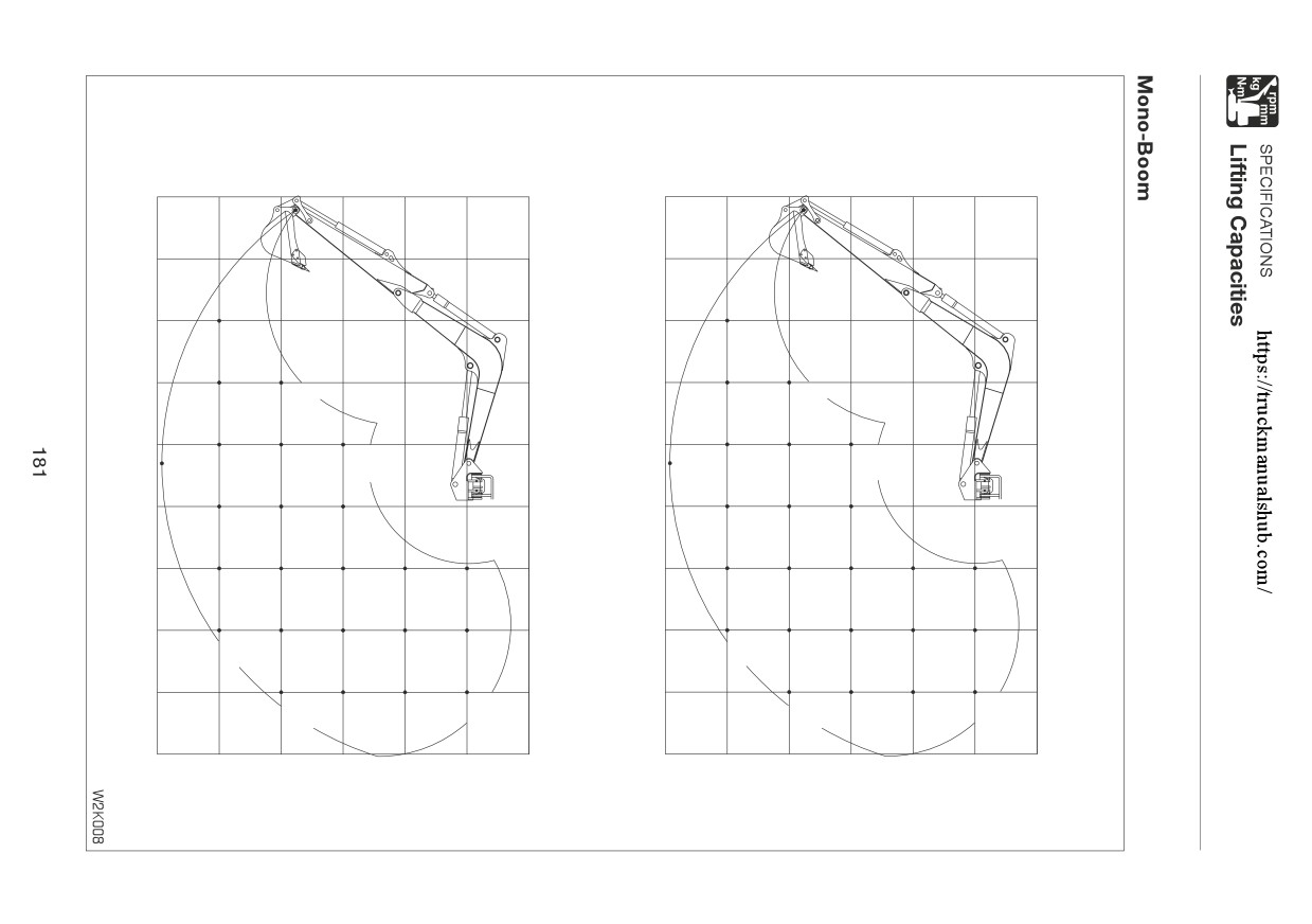
Over Front
Over Side
1355*
1355*
m ft
m ft
(3047*)
(3047*)
6.0
(19.7)
6.0
(19.7)
5.0
(16.4)
5.0
(16.4)
4.0
(13.1)
4.0
(13.1)
1340*
1084
(3013*)
(2438)
3.0
(9.8)
3.0
(9.8)
1454*
1436*
1070
1436*
(3268*)
(3229*)
(2405)
(3229*)
2.0
(6.6)
2.0
(6.6)
1538
1984*
2730*
1033
1496
2731
1143
(3457)
(4460*)
(6138*)
751
(2322)
(3363)
(5330)
(2570)
(1688)
1.0
(3.3)
1.0
(3.3)
1493
2124
3381
991
1410
2180
(3357)
(4774)
(7600)
(2229)
(3170)
(4902)
0
0
1460
2060
3276
2717*
1993*
960
1351
2088
2717*
1993*
(3282)
(4631)
(7365)
(6107*)
(4481*)
(2158)
(3038)
(4694)
(6107*)
(4481*)
-1.0
(-3.3)
-1.0
(-3.3)
1451
2036
3253
4578*
3385*
952
1329
2068
4181
3385*
(3262)
(4577)
(7313)
(10291*)
(7611*)
(2139)
(2989)
(4648)
(9399)
(7611*)
-2.0
(-6.6)
-2.0
(-6.6)
2060
3289
6930*
5199*
1351
2099
4272
5199*
(4630)
(7394)
(15580*)
(11689*)
(3037)
(4720)
(9604)
(11689*)
-3.0
(-9.8)
-3.0
(-9.8)
m
6.0
5.0
4.0
3.0
2.0
1.0
0
m
6.0
5.0
4.0
3.0
2.0
1.0
0
ft
(19.7)
(16.4)
(13.1)
(9.8)
(6.6)
(3.3)
ft
(19.7)
(16.4)
(13.1)
(9.8)
(6.6)
(3.3)
units : daN (lbs.)
182
OPTIONS
General Precautions
184
Swing Stopper
186
Biodegradable Oil
187
Second Auxiliary Hydraulics
188
Third Auxiliary Hydraulics
190
Fourth Auxiliary Hydraulics
192
Hydraulic Breaker
194
Load Safety Device
196
Fuel Supply Pump
198
Outrigger
199
Air Conditioner
200
Optional Equipment Mass
209
183
OPTIONS
General Precautions
Precautions on Safety
WARNING
Heed the following when removing or installing an attachment or option:
Consult with a Takeuchi before installing optional attachments.
Do not use attachments that have not been approved by Takeuchi. Doing so may
compromise safety or adversely affect the machine’s operation or service life.
Takeuchi will not be held responsible for any injuries, accidents or damage to products
caused by the use of a non-approved attachment.
Choose a flat, hard surface to perform the operations. Also make sure there is enough
light and good ventilation.
Clean the area, remove any articles that may get in the way or be dangerous, and
remove any spilt oil or grease.
When performing lifting operations, determine a person to lead the operations and
always follow that person’s instructions.
• Follow the leader’s instructions on operating methods and procedures.
• Determine a signal leader and heed this person’s signals.
When removing or installing the hoe attachment, place it in a stable position so that
it does not tip over.
Due to the risk of loads falling and/or hitting people, do not allow unauthorized
personnel in the work area.
Use the crane to carry heavy objects (25 kg (55 lb.) or greater).
When removing heavy parts, be sure to prop them up before removing them. When
lifting them with a crane, be careful to balance them properly.
Operating with loads suspended with the crane is dangerous. Place loads on a stand
and check for safety.
When attaching the boom or arm, failure to follow proper procedures could result in
serious damage. Consult with a Takeuchi dealer beforehand.
Precautions on Installing Attachments
After replacing optional attachments or other special attachments, test-run them, then inspect
the hydraulic oil level and add oil if necessary.
In addition, consult with a Takeuchi dealer for details of removal and installation procedures.
184
OPTIONS
General Precautions
Precautions on Operating Attachments
WARNING
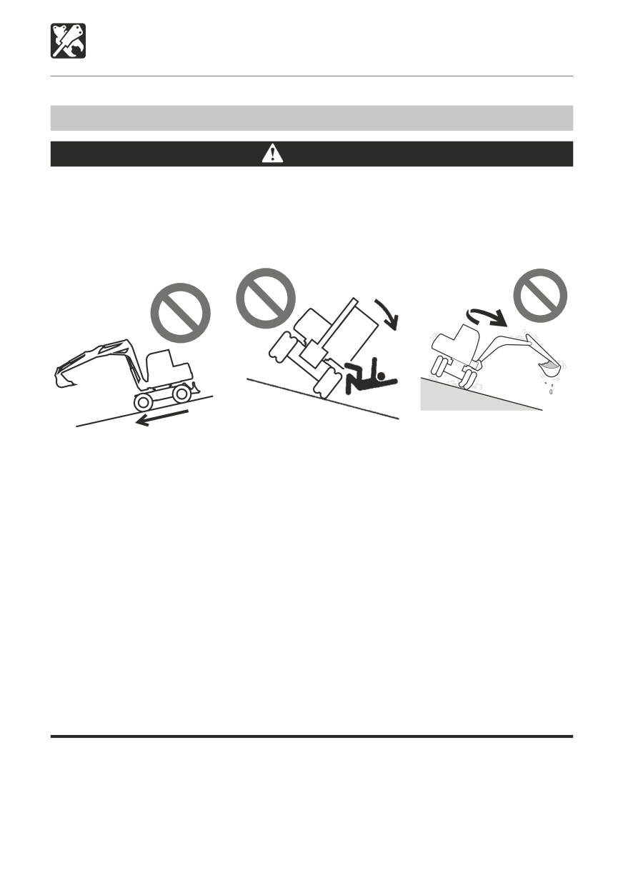
Long attachments reduce machine stability. When traveling down steep slopes or
slewing on slopes, the machine may loose its balance and tip over.
The following operations are particularly dangerous. Do not perform them.
Traveling down slopes
Traveling across slopes
Slewing on slopes
with the attachment lifted
W2L006
W2L004
W2L005
When heavy attachments are installed, the overslew (the distance from where the
operation to stop slewing is performed until slewing stops completely) increases and
mistakes in judgment may result in the attachment hitting surrounding objects. Allow
for plenty of room between the attachment and obstacles.
In addition, the natural drop (the gradual dropping of the attachment under its own
weight when it is stopped in midair) also increases when heavy attachments are
installed.
The machine can tip over more easily in the lateral direction than in the longitudinal
direction.
• Do not slew (swing) sideways with excessive weight at the front. In particular do not
slew sideways on slopes.
• The front is heavier for machines equipped with breakers, crushers or telescopic
arms than for machines equipped with the standard bucket. Do not operate such
machines sideways, especially with the digging arm (boom) downhill.
When a long arm or a telescopic arm is installed, the operating range suddenly
increases and mistakes in judgment may result in the attachment hitting surrounding
objects. Allow for plenty of room between the attachment and obstacles.
185
OPTIONS
Swing Stopper
WARNING
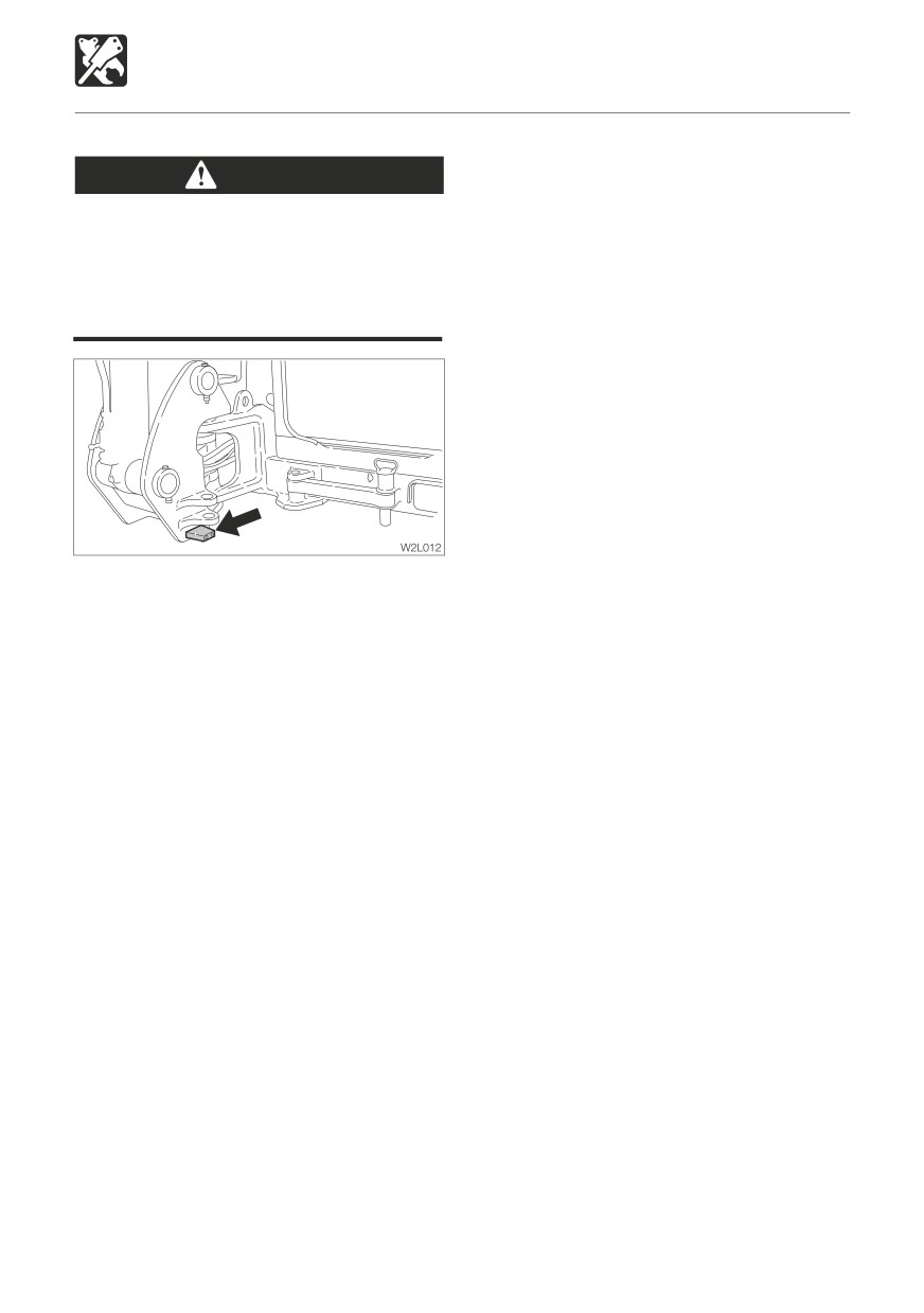
Install a swing stopper when a bucket wider
than the standard bucket is installed.
Failure to mount the swing stopper may
result in the bucket hitting the machine
body.
186
OPTIONS
Biodegradable Oil
Biodegradable oil
Biodegradable oil is a new type of hydraulic oil that is decomposed into carbon dioxide and
water by microorganisms in the soil and water. It is highly safe for living organisms and offers
advantages in terms of environmental protection.
Recommended biodegradable oil: Mobile EAL Envirosyn 46H (an ester synthetic oil).
When replacing the hydraulic oil with biodegradable oil, use the above or an equivalent oil.
Note that other oils, even other brands of ester synthetic oils, may damage O-rings, packings
and seals. Takeuchi products shipped with the optional biodegradable oil are shipped with
the above brand of oil.
When switching from a mineral oil to a biodegradable oil, the parking brake torque decreases
by about 30%.
Replacing the hydraulic oil with biodegradable oil
Mixing mineral oil with biodegradable oil will result in a decrease of the hydraulic oil’s performance
as well as a decrease in biodegradability and safety. The hydraulic oil system must be flushed
as described below before supplying the biodegradable oil. This operation is dangerous and
requires experience. Have it performed by a Takeuchi sales or service outlet.
Flushing
To be performed by a Takeuchi sales or service outlet
1. Drain the hydraulic oil (mineral oil) from the hydraulic tank and clean the inside of the tank
and suction strainer.
(Refer to the section on replacing the hydraulic oil and cleaning the
suction strainer.)
2. Remove the cylinder hoses and drain the hydraulic oil (mineral oil) from inside the
cylinders.
3. Supply new biodegradable oil to the hydraulic tank.
4. Bleed the air from the hydraulic pump, control valve, slew motor and cylinders.
5. Operate the hydraulic devices for 30 minutes.
6. Drain the biodegradable oil from the tank and cylinders.
7. Replace the hydraulic oil return filter with a new filter.
8. Repeat steps 3 and 4.
9. Operate the hydraulic devices for 30 minutes.
10. Drain the biodegradable oil from the tank and cylinders.
11. Repeat steps 3 and 4.
12. Operate the hydraulic devices for 1 hour.
13. Drain the biodegradable oil from the tank and cylinders.
14. Replace the return filter with a new filter.
15. Repeat steps 3 and 4.
16. Operate the hydraulic devices, then check for oil leakage.
There is no need to flush the hydraulic oil system when switching from biodegradable to
mineral hydraulic oil.
187
OPTIONS
Second Auxiliary Hydraulics
c. Stop the engine and wait for more than
Second Auxiliary Hydraulic Lines
5 minutes until bubbles escape from the
hydraulic oil in the tank.
WARNING
Oil may spurt out if caps or filters are
IMPORTANT: Follow the procedures for
removed or pipes disconnected before
purging air as instructed by the attachment
releasing the pressure in the hydraulic
manufacturer if specified to do so.
system.
When disconnecting hoses, release the
6. Check for leaks.
internal pressure before removing.
These lines deliver the hydraulic oil necessary
for operating a hydraulic attachment.
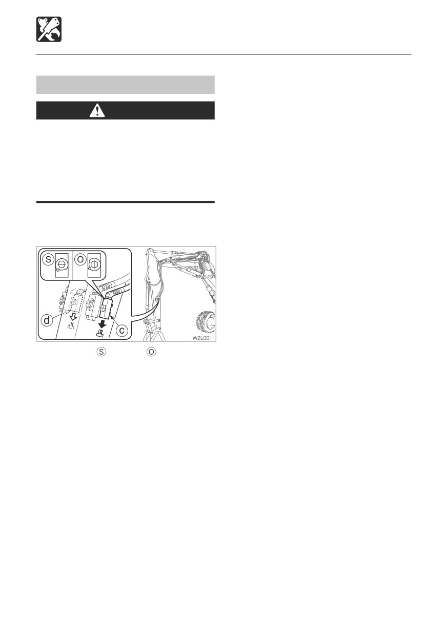
Stop valve
: Closed
: Open
Connecting the Hydraulic Circuits
To connect the attachment hydraulic lines,
use the following procedures:
1. Release the pressure remaining in the lines
then close the stop valve.
Refer to
“Releasing the residual
pressure”.
2. Remove the plugs.
3. Connect the attachment hydraulic lines to
ports (c) and (d).
4. Open the stop valves.
5. When connecting is complete, purge air
from the hydraulic lines.
a. Start and run the engine at low idle with
no load for 10 minutes.
b. With the engine running at low idle
operate the auxiliary hydraulic switches
repeatedly (approx. 10 times) to purge
air from the hydraulic lines.
188
OPTIONS
Second Auxiliary Hydraulics
Second Auxiliary Hydraulic Switch
(Proportional control)
D
C
W2B019
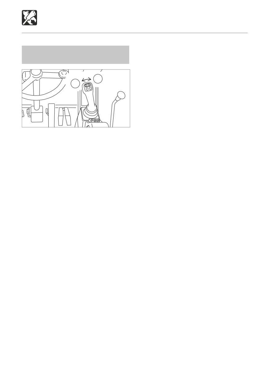
Move this switch to control
the flow of the oil
in the second auxiliary hydraulic lines.
(C)
Hydraulic oil flows to left auxiliary
line(c)
(D)
Hydraulic oil flows
to right auxiliary
line(d)
Disconnecting the hydraulic circuits
1. Release the pressure remaining in the lines
then close the stop valve.
Refer to
“Releasing the residual
pressure”.
2. Disconnect the lines from ports (c) and
(d).
3. Install the plugs.
Releasing the residual pressure
After using the auxilliary hydraulic circuits,
pressure remains in the circuits. This is called
the residual pressure. Release this residual
pressure before disconnecting the lines.
1. Stop the engine.
2. Turn the starter switch to the ON
position.
3. Fully lower the safety lock lever.
4. Within 10 minutes after the engine comes
to a complete stop, move the 2nd auxiliary
hydraulic switch to the right and left several
times.
5. Raise the safety lock lever to the lock
position.
189
OPTIONS
Third Auxiliary Hydraulics
IMPORTANT: Follow the procedures for
Third Auxiliary Hydraulic Lines
purging air as instructed by the attachment
manufacturer if specified to do so.
WARNING
Oil may spurt out if caps or filters are
5. Check for leaks.
removed or pipes disconnected before
releasing the pressure in the hydraulic
system.
When disconnecting hoses, release the
internal pressure before removing.
These lines deliver the hydraulic oil necessary
for operating a quick attachment.
Connecting the Hydraulic Circuits
To connect the attachment hydraulic lines,
use the following procedures:
1. Release the pressure remaining in the
lines.
Refer to
“Releasing the residual
pressure”.
2. Remove the plugs.
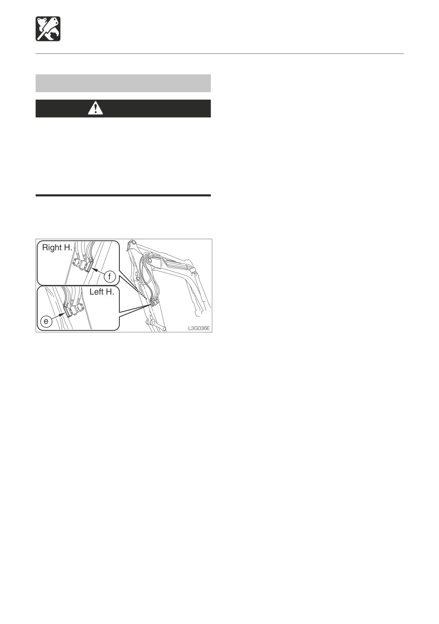
3. Connect the attachment hydraulic lines to
ports (e) and (f).
4. When connecting is complete, purge air
from the hydraulic lines.
a. Start and run the engine at low idle with
no load for 10 minutes.
b. With the engine running at low idle
operate the auxiliary hydraulic switches
repeatedly (approx. 10 times) to purge
air from the hydraulic lines.
c. Stop the engine and wait for more than
5 minutes until bubbles escape from the
hydraulic oil in the tank.
190
OPTIONS
Third Auxiliary Hydraulics
Third Auxiliary Hydraulic Switch
Third Auxiliary Hydraulics Warning
and Button
Lamp
1
2
W2B020
L7L010
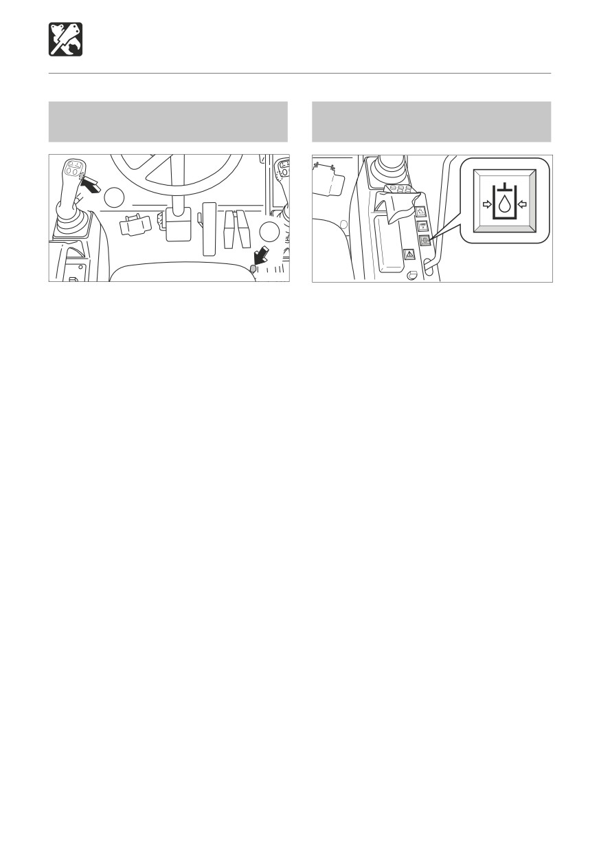
Press those switch and button to control the
This lamp illuminates and an alarm sounds
flow of the oil in the third auxiliary hydraulic
when the third auxiliary hydraulic pressure
lines.
drops abnormally while the engine is
When the safety lock lever is released after
running.
the engine is started, hydraulic oil constantly
flows in pipe (e). When button (1) and switch
(2) are pressed simultaneously, the oil flow
switches to pipe (f). When this happens,
the pressure of pipe (e) drops, an alarm is
sounded and the warning lamp lights. For
safety, only operates when both button (1)
and switch (2) are pressed.
Disconnecting the hydraulic circuits
1. Release the pressure remaining in the
lines.
Refer to
“Releasing the residual
pressure”.
2. Disconnect the lines from ports (e) and
(f).
3. Install the plugs.
Releasing the residual pressure
After using the auxilliary hydraulic circuits,
pressure remains in the circuits. This is called
the residual pressure. Release this residual
pressure before disconnecting the lines.
1. Stop the engine.
(The residual pressure is released from the
(e) port line.)
191
OPTIONS
Fourth Auxiliary Hydraulics
IMPORTANT: Follow the procedures for
Fourth Auxiliary Hydraulic Lines
purging air as instructed by the attachment
manufacturer if specified to do so.
WARNING
Oil may spurt out if caps or filters are
5. Check for leaks.
removed or pipes disconnected before
releasing the pressure in the hydraulic
system.
When disconnecting hoses, release the
Selector Button (2 or 4 Aux.)
internal pressure before removing.
These lines deliver the hydraulic oil necessary
for operating a hydraulic attachment.
L7L020
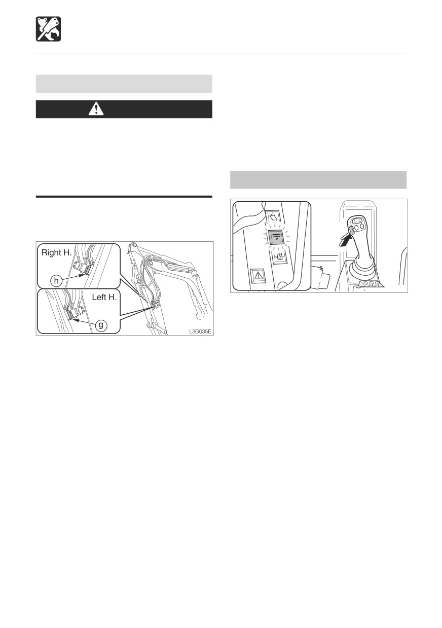
This button changes from the fourth auxiliary
hydraulics operation to the second auxiliary
hydraulics operation.
Press this button to change over to operation
Connecting the Hydraulic Circuits
of the second auxiliary hydraulics. The second
To connect the attachment hydraulic lines,
auxiliary hydraulics operation indicator lamp
use the following procedures :
will light. One more press of this button will
1. Release the pressure remaining in the
result in a return to fourth auxiliary hydraulics
lines.
operation. Actual operation is performed with
Refer to
“Releasing the residual
the second / fourth auxiliary hydraulic switch
pressure”.
(slider switch).
2. Remove the plugs.
3. Connect the attachment hydraulic lines to
ports (g) and (h).
4. When connecting is complete, purge air
from the hydraulic lines.
a. Start and run the engine at low idle with
no load for 10 minutes.
b. With the engine running at low idle
operate the auxiliary hydraulic switches
repeatedly (approx. 10 times) to purge
air from the hydraulic lines.
c. Stop the engine and wait for more than
5 minutes until bubbles escape from the
hydraulic oil in the tank.
192
OPTIONS
Fourth Auxiliary Hydraulics
b. Move the second / fourth auxiliary
Second / Fourth Auxiliary
hydraulic switch to the right and left
Hydraulic Switch
several times.
5. Raise the safety lock lever to the lock
position.
Selector Button (2-Piece boom)
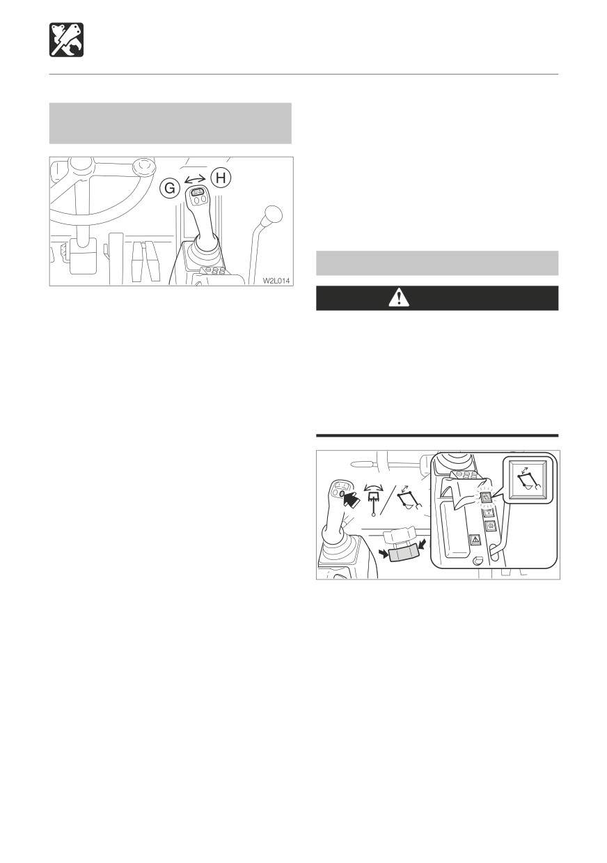
Move this switch to control the flow of the oil
WARNING
in the fourth auxiliary hydraulic lines.
Pressing (switching ON or OFF) the
selector button while the boom swing
(G)
Hydraulic oil flows to left auxiliary line(g)
pedal is depressed is dangerous, since the
(H)
Hydraulic oil flows to right auxiliary line(h)
attachment will move unexpectedly.
Always set the boom swing pedal back to
When the safety lock lever is set to the lock
the neutral position before operating the
position, this control is locked.
selector button.
Disconnecting the hydraulic circuits
1. Release the pressure remaining in the
lines.
Refer to
“Releasing the residual
pressure”.
2. Disconnect the lines from ports (g) and (h).
3. Install the plugs.
Releasing the residual pressure
W3L010
After using the auxilliary hydraulic circuits,
This button changes from the boom
pressure remains in the circuits. This is called
swing operation to the intermediate boom
the residual pressure. Release this residual
operation.
pressure before disconnecting the lines.
While the button is pressed and held in,
1. Stop the engine.
operation changes from the boom swing
2. Turn the starter switch to the ON
operation to the intermediate boom operation
position.
and the intermediate boom operation indicator
3. Fully lower the safety lock lever.
lamp lights. When the finger is released from
4. Within 10 minutes after the engine comes
the button, operation switches back to
to a complete stop, move the second /
boom swing operation. Actual operation is
fourth auxiliary hydraulic switch to the right
performed with the boom swing pedal.
and left several times.
Operation of the first auxiliary hydraulic switch
a. Press the selector button (2nd or 4th
push button: left side (A’) only.
Aux.) to change over to operation of the
second auxiliary hydraulics.
193
OPTIONS
Hydraulic Breaker
For handling of the breaker, read the hydraulic
breaker’s manual, provided separately.
IMPORTANT: When mounting devices,
select devices suited for this machine.
For advice on selecting device, contact a
Takeuchi sales or service outlet.
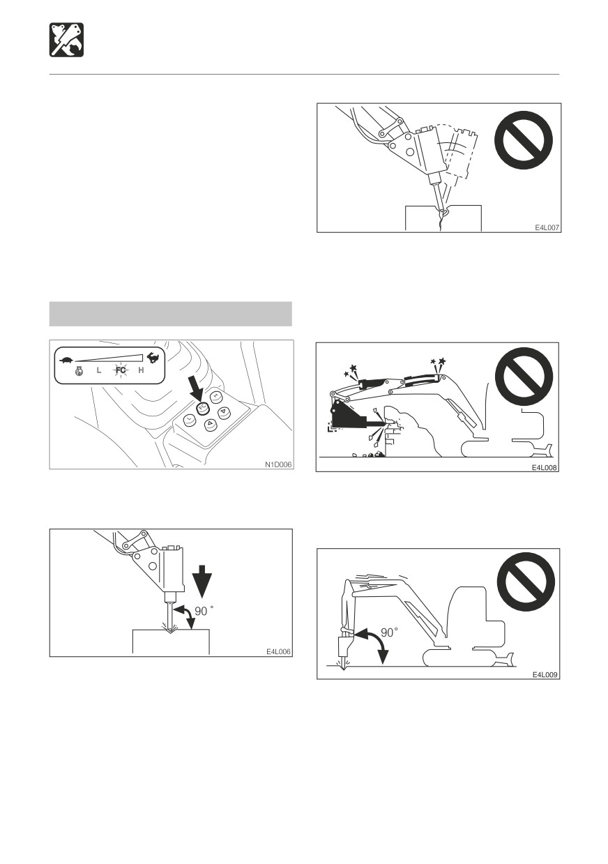
Do not pry with the chisel, and do not pry
while pounding.
Do not move the chisel while pounding.
Do not pound continuously for over 30
Precautions on Operating
seconds on the same surface.
Run the engine with 75% the maximum
Do not pound with the cylinder fully
speed.
extended or contracted (at the stroke end).
Leave a margin of at least 5 cm.
Pressing force
Pound with the chisel perpendicular to the
surface you are pounding.
Do not pound with the arm perpendicular
When pounding, press the chisel properly
to the ground surface.
against the object to be broken so as to
avoid pounding the air.
194
OPTIONS
Hydraulic Breaker
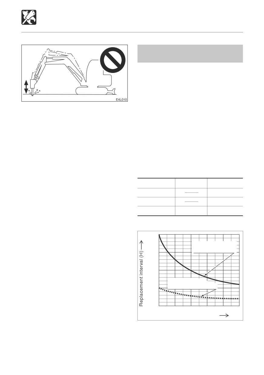
Replace the hydraulic oil
regularly!
When using a hydraulic breaker, the oil
deteriorates quicker than during normal
digging. Be sure to replace the hydraulic oil
and return filter element.
Failure to replace these in time can lead
to damage to the machine and breaker’s
Do not drop the breaker itself on the object
hydraulic systems. In order to improve the
to be broken in order to break it.
service life of the hydraulic systems, be
Do not move objects to be broken or rocks
sure to replace the hydraulic oil and return
with the breaker itself.
filter element after the number of hours
Slew occasionally to cool the engine.
shown on the diagram below.
If a hydraulic hose is vibrating abnormally,
Clean the suction strainer when changing
nitrogen gas may be leaking from the
the return filter element.
accumulator. Have an inspection as soon
as possible.
Replacement Interval (Hours)
Item
Hydraulic Oil
Filter Element
1st time
25
2nd time
100
Periodically
600
200
When the breaker operating ratio is 100%
2000
Replacement interval
for hydraulic oil
1500
1000
Replacement
interval for filter element
500
0
20
40
60
80
100
Breaker operating ratio (%)
N0G036
195
OPTIONS
Load Safety Device
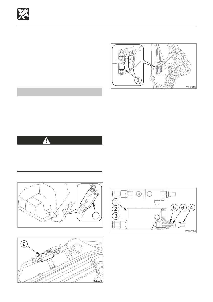
The load safety devices include an emergency
Intermediate Boom (2-Piece boom)
shut-off valve and an overload warning
device. The emergency shut-off valve stops
the boom, intermediate boom or arm part
way through a fall. The overload warning
device sounds an alarm when an excessive
load is applied.
Emergency shut-off valve
If the emergency shut-off valve (1), (2) or (3)
When the hose of the boom, intermediate
is activated, immediately set the operating
boom or arm cylinders are ruptured and the
levers or swing pedal to the neutral position.
boom, intermediate boom or arm falls, the
Do not move the operating levers or swing
emergency shut-off valve is activated and
pedal to the boom, intermediate boom or arm
stops the boom, intermediate boom or arm
lowering side. Contact a Takeuchi dealer for
part way through the fall.
maintenance.
If the engine can be started, the boom,
WARNING
intermediate boom or arm can be lowered
If the boom, intermediate boom or arm
with the operating lever or swing pedal.
drops and the emergency shut-off valves
Check for safety, then slowly lower the boom,
are activated, immediately move away
intermediate boom or arm.
from the suspended object.
If the engine cannot be started, the boom,
intermediate boom or arm can be lowered
Boom
using the procedure described below.
1
W2L008
Arm
1. Check for safety in the working area and for
stability of the machine and lifted load.
2. Remove the cap (4).
3. Loosen the lock nut (5).
4. Tighten the stem (6) to lower the boom.
5. Check for stability of the hoe attachment
and load.
6. Loosen the stem (6) secure it with the lock
nut (5).
196
OPTIONS
Load Safety Device
Overload Warning Device
If a weight greater than the machine is
designed to lift is lifted, the overload warning
device is activated and a horn is sounded
(when the overload warning switch is turned
on).
WARNING
Continuing to apply the load after the
overload warning horn sounds could
result in the machine tipping over or the
emergency shut-off valve being activated.
If the horn sounds, stop operating the
machine and lighten the load.
2
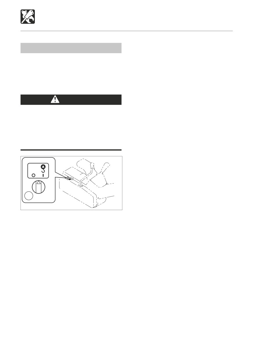
L3L0061
Overload warning switch (2)
O position
OFF
I position
ON
When the emergency shut-off valve is
activated, the overload warning horn stops.
(This is because the pressure sensor can no
longer detect hydraulic pressure.)
197
OPTIONS
Fuel Supply Pump
This device automatically supplies fuel to the
fuel tank and stops automatically when the
fuel tank is full.
DANGER
Do not use the fuel supply pump for
gasoline or hydraulic oil. Doing so could
result in explosion or damage.
Only use the fuel supply pump for diesel
fuel.
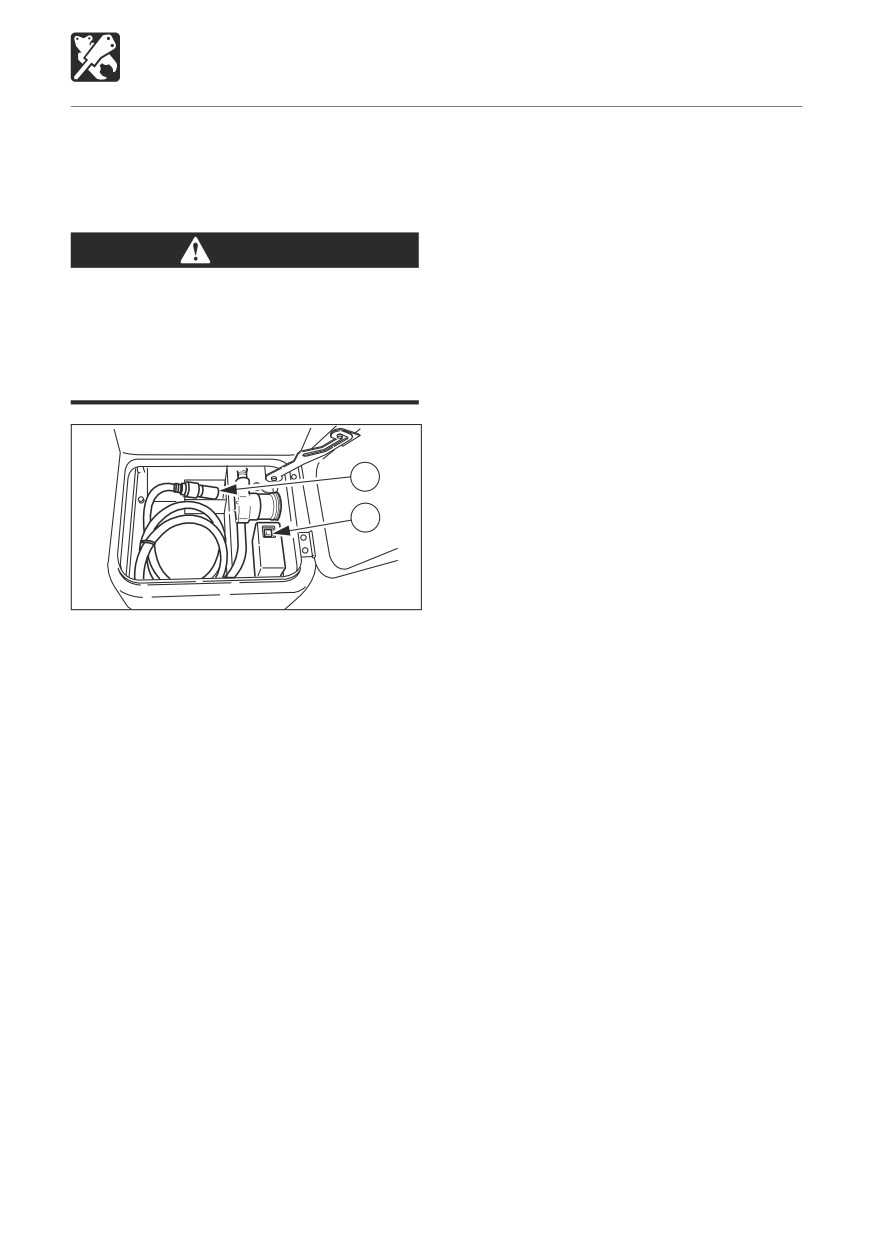
1
2
L3L013
1. Open the front cover.
2. Insert the pump’s nozzle (1) in the fuel
supply tank.
3. Press the switch (2).
The pump stops automatically once the
fuel tank is full.
198
OPTIONS
Outrigger
WARNING
Provide firm uniform supporting surface
for outrigger pads.
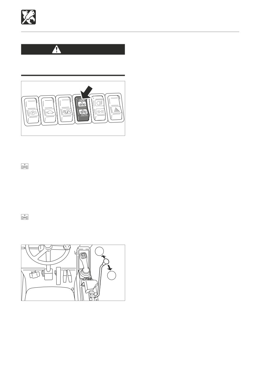
W2L0022
Depress the axle lock switch to change into
the outrigger operation.
LOCK
Outrigger operation
(The suspension lock is
engaged)
Neutral
Dozer blade operation
(The suspension lock is
disengaged)
............ Dozer blade operation
AUTO
(When the suspension lock is
disengaged)
B
A
W2B031
The outrigger operation is
done by the blade
lever.
(A)
Outriggers Raise
(B)
Outriggers Lower
199
OPTIONS
Air Conditioner
CAUTIONS ON USE
Do not overcool
For health purposes, the air inside the cab
Ventilate periodically
should be kept at a temperature at which
When using the air conditioner over an
you feel a little cool when entering the cab
extended period of time, open the windows
from outside (a difference of 5 to 6°C (41 to
about once each hour to let in fresh air.
43°F)). Be careful to adjust the temperature
Your eyes may become irritated if you
properly.
smoke while using the air conditioner. If
this happens, open the windows to let
in fresh air. Cigarette smoke particularly
Do not turn the air conditioner on
irritates the eyes when using the air
until the engine is started
conditioner because the humidity in the
To avoid placing an excessive load on the
cabin drops and the eyes’ membranes
compressor, wait until the engine is started
tend to become dry.
and is running smoothly before turning on
If the outside air is dirty, set the air
the air conditioner.
conditioner to the recirculation mode.
Let hot air out first
Always maintain good visibility
If the excavator has been parked in the sun,
Working with the windows dirty or fogged
open the windows or door to let the hot air out
restricts visibility and is dangerous. Always
of the cab before using the air conditioner.
clean dirt and moisture off the windows
before working.
The windows tends to get foggy when the
humidity is high. If this happens, turn on the
Caution on refrigerant (gas)
air conditioner and use outside air and the
defroster to get rid of the fog.
Exposure of the eyes or hands to the cooler’s
If the air conditioner is set to high when
refrigerant could result in blindness or
using the defroster, the difference between
frostbite. Never touch the refrigerant or loosen
the external and internal temperatures
the parts of the cooling circuit.
increases, and fog may form on the
Should the refrigerant gas leak, keep flames
outside of the windows. If this happens,
away.
either turn the air conditioner off or turn
the temperature control dial clockwise to
increase the internal temperature.
Mist may blow out of the air outlets. This
is not a malfunction. When moist air
passes through the air conditioner unit’s
evaporator, water particles in the air freeze
and are emitted as mist.
200