Takeuchi Hydraulic Excavator TB175W (No. 175400095~). Operator's Manual - page 4
MAINTENANCE
Daily Inspection (Every 10 Hours)
Inspecting and Inflating the Tires
WARNING
W2G006
During your pressure checks, also inspect
for:
Objects wedged between duals or
W2A024
embedded in tires.
Mismatched duals. Diameters should be
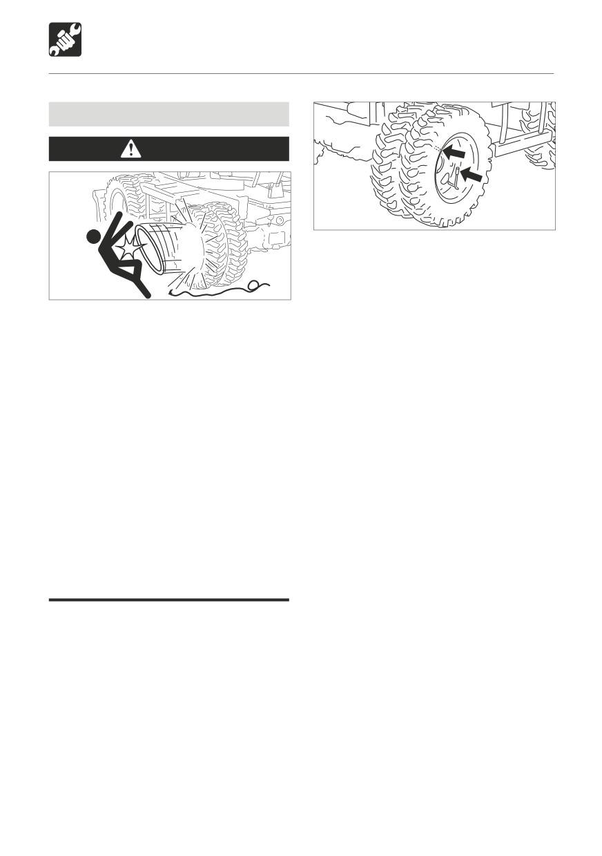
Explosive separation of a tire and/or rim
equal as well as amount of tread wear.
parts can cause serious injury or death.
Missing valve caps and wheel lugs.
Always follow the service outlet or see
Cuts, tears, and breaks that may need
your tire supplier.
rapair.
Do not inflate tires with flammable
Abnormal or uneven wear.
gases or from systems utilizing an
Damaged or poor fitting rim or irm
alcohol injector.
flanges.
Never cut or weld on a wheel with an
Projecting body hardware, loose fender
inflated tire mounted on it. This could
bolts, spring clips - anything that could
cause explosive decompression.
contact a tire.
Always use a safety cage or cable
restraints when reinflating a repaired
tire.
A rise in tire pressure during operation is
normal, and should NOT be reduced.
Always maintain the correct tire
pressure. Do not inflate the tires above
the recommended pressure.
Recommended air pressure must be
maintaind in every tire. Dairy checks assure
that inflation is correct. If your periodic check
discloses a tire that is continuously losing air,
a leak is indicated and must be repaired.
121
MAINTENANCE
Daily Inspection (Every 10 Hours)
Inflating the tires
Checking the wheel nut torques
These instructions are for adding air to a
tire which is already inflated. If the tire has
WARNING
lost all its air pressure, call in a qualified tire
If, for whatever reason, wheel nut is
mechanic. The tire mechanic should use a
renewed, all the nuts for that wheel must
tire inflation cage and the correct equipment
be changed as a set, since the remaining
to do the job.
nuts may have been damaged.
1. Prepare the wheel.
On new machines, and whenever a wheel has
Before you add air to the tire, make sure it is
been removed, check the wheel nut torques
correctly fitted on the machine or installed
every two hours until they stay correct.
in a tire inflation cage.
Every day, before starting work, check that
2. Prepare the equipment.
the wheel nuts are tight.
Use only an air supply system which
• Tightening torque:
includes a pressure regulator.
400 to 500 N·m (295 to 369 ft-lb.)
Set the regulator no higher than above the
recommended tire pressure. (See below).
Use
an air hose fitted with a self locking air
chuck and remote shut-off valve.
W2A031
3. Add the air.
Make sure that the air hose is correctly
connected to the tire valve.
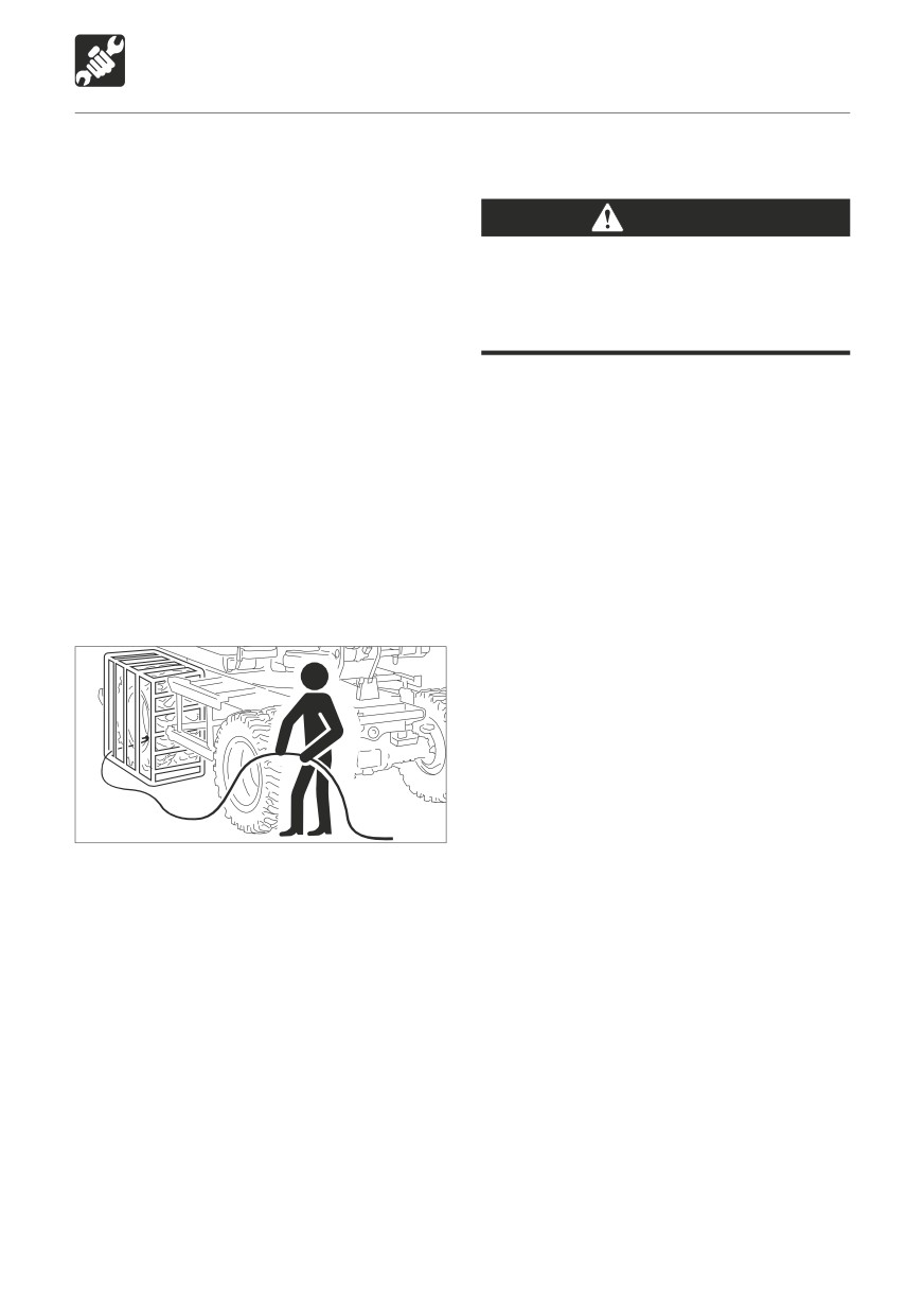
Clear other people from the area.
Stand behind the tread of the tire while
adding the air.
Inflate the tire to the recommended
pressure. Do not over-inflate.
• 8.25 - 20 Twin tires
• Tire pressure: 600kPa(87 psi)
122
MAINTENANCE
After First 50 Hours (New Machines Only)
Replacing the Hydraulic Oil
4
Return Filter
10
1
5
WARNING
8
Stop the engine and allow the machine
9
to cool down before performing
maintenance.
• The engine, hydraulic lines and many
other parts of the machine are hot
6
directly after the engine is stopped.
Touching these parts will cause
burns.
• The hydraulic fluid is also hot and
under high pressure.
7
Be careful when loosening caps and
L7G020
plugs. Working on the machine under
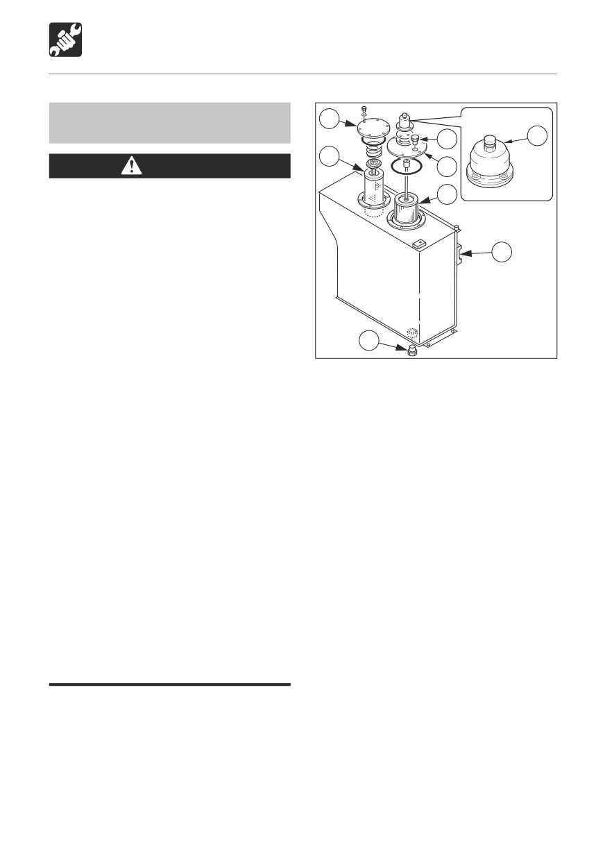
1. Press button (1) and bleed the air from the
these conditions could result in burns
tank.
or injuries due to the hot oil spurting
2. Loosen the bolts, and remove the flange
out.
(4).
Never jump off the machine. Use the
3. Remove the return filter (5).
steps and handrails when climbing on
4. Install the new return filter.
and off the machine, and always support
5. Install the flange (4).
your body at three points with your
6. Inspect the level with the sight gauge (6),
hands and feet.
and replenish if the level is low.
Oil may spurt out if caps or filters are
Refer to page 118 “Inspecting the Hydraulic
removed or pipes disconnected before
Oil Level and Replenishing”.
releasing the pressure in the hydraulic
system.
• Gradually press the air breather button
to relieve tank pressure.
• When removing plugs or screws or
disconnecting hoses, stand to the
side and loosen slowly to gradually
release the internal pressure before
removing.
123
MAINTENANCE
After First 50 Hours (New Machines Only)
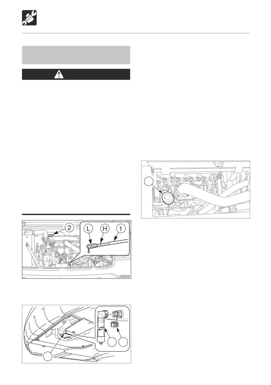
2. Loosen the bolts and remove the under
Replacing the Engine Oil and Oil
cover.
Filter
3. Place a pan for catching the spent oil under
the drain plug (3).
WARNING
4. Remove cap (A), install connector (B) and
Stop the engine and allow the machine
drain the oil. (The oil comes out when the
to cool down before performing
screw is tightened.)
maintenance.
5. Remove connector (B) and install cap (A).
• The engine, muffler, radiator and
many other parts of the machine
IMPORTANT: Check the spent oil. If it
are hot directly after the engine is
contains large amounts of metal powder,
stopped. Touching these parts will
consult a Takeuchi sales or service
cause burns.
outlet.
• The engine oil is also hot.
6. Install the under cover.
Be careful when loosening caps
and plugs. Working on the machine
under these conditions could result
in burns.
Never jump off the machine. Use the
4
steps and handrails when climbing on
and off the machine, and always support
your body at three points with your
hands and feet.
L3G030
7. Open the maintenance cover.
8. Using a filter wrench, turn the filter (4)
counterclockwise and remove it.
9. Clean the surface of installation of the filter
stand.
10. Apply a thin layer of oil to the packing of
the new filter.
11. Install the new filter by hand.
1. Open the engine hood and remove the oil
12. Tighten 3/4 more turn with the filter
supply cap (2).
wrench after the filter packing comes in
contact with the surface of installation.
13. Supply oil up to the upper limit (H) of the
dipstick (1). Problems could arise if the
oil level is either too low or too high.
14. Tighten the oil supply cap (2).
15. Start the engine, run it at low idle for about
B
A
3 minutes, then stop it.
16. After about 10 minutes, inspect the oil
3
level.
L3G025
124
MAINTENANCE
After First 50 Hours (New Machines Only)
Adjustment
Inspecting and Adjusting the Fan
Belt
6
5
WARNING
Stop the engine and allow the machine to
cool down before performing inspection
4
and maintenance.
The engine, muffler, radiator, hydraulic
W3G030
lines, sliding parts and many other parts
of the machine are hot directly after the
1. Loosen the locking nut (6).
engine is stopped. Touching these parts
2. Turn the adjustment bolt (5) and adjust the
will cause burns.
fan belt (4).
• Tighten: Clockwise
Inspection
• Loosen: Counterclockwise
1. Open the engine hood.
3. Tighten the locking nut (6).
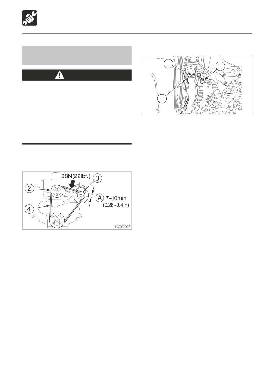
2. Press at the center of the fan pulley (2) and
alternator pulley (3) and check the tension
(about 98 N or 22 lbf.).
The slack (A) should be about 7 to 10 mm
(0.28 to 0.4 in).
3. Inspect the fan belt (4) and replace it if:
• there are cuts or cracks.
• the belt is worn and touches the bottom
of the V groove in the pulley.
• the belt stretches and cannot be
adjusted.
125
MAINTENANCE
After First 50 Hours (New Machines Only)
7. Inspect the level with the sight gauge, and
Replacing the Pilot Line Filter
replenish if the level is low.
Refer to page 118 “Inspecting the Hydraulic
WARNING
Oil Level and Replenishing”.
Stop the engine and allow the machine
to cool down before performing
maintenance.
• The engine, hydraulic lines and many
other parts of the machine are hot
directly after the engine is stopped.
Touching these parts will cause
burns.
• The hydraulic fluid is also hot and
under high pressure.
Be careful when loosening caps and
plugs. Working on the machine under
these conditions could result in burns
or injuries due to the hot oil spurting
out.
Oil may spurt out if caps or filters are
removed or pipes disconnected before
releasing the pressure in the hydraulic
system.
• Gradually press the air breather button
to relieve tank pressure.
3
2
1
W2G009
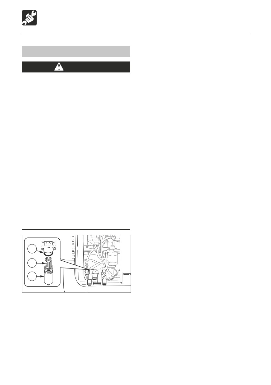
1. Open the right side cover.
2. Turn the case (1) counterclockwise and
remove it.
3. Remove the element (2) and O-ring (3).
4. Clean the inside of the case (1).
5. Install the new element in the case (1).
6. Set the new O-ring, then tighten the case
(1).
126
MAINTENANCE
Every 50 Hours
5. Repeat steps 2 to 4 above three times.
Lubricating the Slew Bearing
6. Wipe off the grease expelled from the slew
bearing and grease nipple.
WARNING
Do not slew while lubricating. Doing so
is dangerous, as you may get caught in
the machine.
W2G010
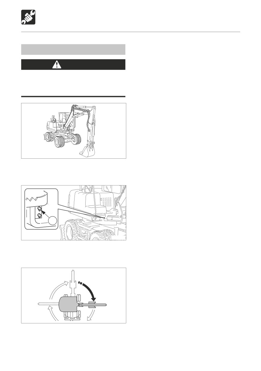
1. Stop the engine with the machine in the
posture shown on the diagram above.
1
W2G011
2. Use the grease gun to supply grease to the
grease nipple (1).
W2G012
3. Start the engine, lift the bucket and slew
clockwise 90°.
4. Ground the bucket and stop the engine.
127
MAINTENANCE
Every 50 Hours
Inspecting the Battery Fluid Level
and Replenishing
DANGER
Do not use the battery when the fluid
level is below the lower level. Doing
so will hasten the deterioration of the
W3G040
internal portions of the battery and
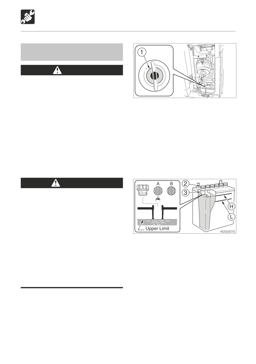
2. Inspect the indicator (1).
shorten the battery life, and can also
• Blue: Good
cause rupturing (or an explosion).
• White: Charging needed
Batteries generate flammable and
• Red: Insufficient battery fluid
explosive gases. Keep arcs, sparks,
3. Inspect the fluid level.
flames and lighted tobacco away.
The fluid level should be between the lines
Use a dampened cloth to clean the area
indicating the upper level (H) and lower
of the fluid level lines and check the fluid
level (L). If not, add distilled water up to
level. Note that if this area is cleaned
line (H).
with a dry cloth, static electricity could
If the fluid level can not be checked by fluid
cause ignition or explosion.
level lines.
WARNING
Do not fill the battery above the upper
level. Doing so could cause the fluid to
leak, contact and damage the skin, or
cause parts to corrode.
Batteries contain sulfuric acid which will
damage eyes or skin on contact.
• If acid contacts eyes, flush immediately
with clean water and get prompt
Remove the caps (2) and look into the fluid
medical attention.
supply holes to check the fluid level. If the
• If acid is accidentally swallowed, drink
fluid is below the sleeve (3), be sure to add
large quantities of water or milk and
distilled water up to the bottom edge of the
call a physician immediately.
sleeve (3).
• If acid contacts skin or clothing, wash
Proper amount
(A)
off immediately with clean water.
The fluid reaches up to the bottom edge
of the sleeve (3), so the surface tension
Inspection
causes the fluid to swell and the plate
IMPORTANT: Check the fluid level of all
appears distorted.
cells, even when the fluid level can be
Level too low
(B)
checked by indicator.
The fluid does not reach up to the bottom
edge of the sleeve (3), so the plate appears
1. Open the left side cover.
laminar, not distorted.
4. Also check the terminals for looseness and
dirt.
128
MAINTENANCE
Every 50 Hours
Replenishing
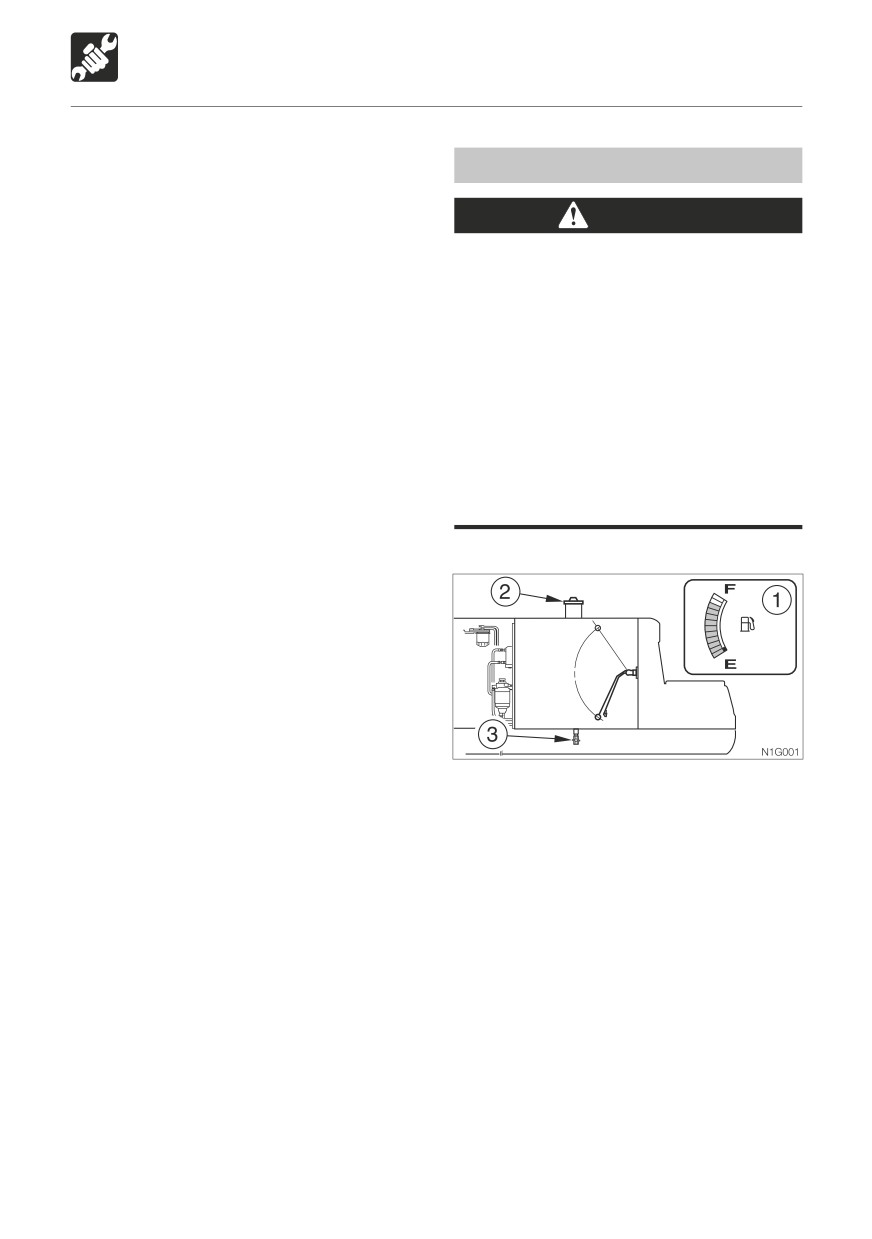
Draining the Fuel Tank
When adding distilled water, do so before
starting operations in order to prevent
WARNING
freezing.
1. Remove the caps (2), and add distilled
Never jump off the machine. Use the
water until the upper level (H).
steps and handrails when climbing on
2. Inspect the indicator (1) then it turns blue.
and off the machine, and always support
3. Clean the cap’s exhaust hole, then tighten
your body at three points with your
the caps (2) securely.
hands and feet.
Do not smoke or permit open flames
while handling fuel or working on the
fuel system.
Stop the engine in a well-ventilated
place and allow it to cool down before
performing maintenance.
Clean up spilled fuel immediately.
Do this before operating the machine.
1. Remove the fuel filler cap (2).
2. Place a pan under the drain cock (3).
3. Open the drain cock (3) and drain the water
and sediment from the bottom of the tank.
4. Close the drain cock (3).
5. While watching the fuel gauge (1), add
fuel.
6. Tighten the fuel filler cap (2) and lock it with
the key.
7. Bleed the air.
Bleeding the air from the fuel system
Refer to page 157 “Bleeding the Air from the
Fuel System”.
Supplement: Air in the fuel system can make
it difficult to start the engine and cause engine
problems. Also bleed the air when the fuel
tank is emptied.
129
MAINTENANCE
Every 250 Hours
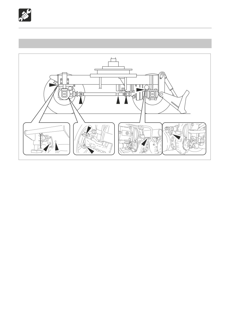
Lubricating the Undercarriage
W2G015
1. Set the machine to the lubrication posture shown in the diagram above, ground the working
equipment, then stop the engine.
2. Use the grease gun to lubricate the grease nipples.
3. Wipe off the expelled grease.
130
MAINTENANCE
Every 250 Hours
Cleaning the Air Cleaner
WARNING
Stop the engine and allow the machine
to cool down before performing
maintenance.
• The engine, muffler, radiator and many
E4G033
other parts of the machine are hot
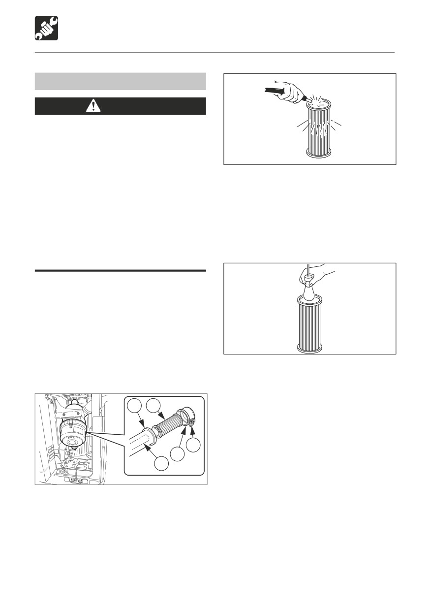
6. Clean the outer element (3) with dried
directly after the engine is stopped.
compressed air {294 to 490 kPa (43 to 71
Touching these parts will cause
psi)}.
burns.
First blow the air from the inside of the
Wear required appropriate equipment
element along the flutes, then blow the air
such as safety glasses and filter mask
from the outside, and finally from the inside
when using compressed air, as metal
again.
fragments or other objects can fly and
cause serious personal injury.
IMPORTANT: Be careful not to scratch
the element. Do not use an element if it is
damaged.
IMPORTANT: When operating the machine
in very dusty places, inspection and
maintenance should be performed every
day.
E4G034
7. Light up the inside of the outer element (3)
1. Open the left side cover.
with a bulb, inspect it, and replace it if there
are small holes or thin spots.
8. Install the outer element (3).
4
3
9. Install the dust cup (2) with the “TOP” mark
at the top, then fasten it with the clamps
(1).
1
2
5
W3G050
2. Loosen the clamps (1) and remove the dust
cup (2).
3. Clean the inside of the dust cup (2).
4. Remove the outer element (3).
Do not remove and clean the inner element
(5).
5. Clean the inside of the body (4).
131
MAINTENANCE
Every 250 Hours
Cleaning the Radiator Fins and Oil
Replacing the Engine Oil and Oil
Cooler Fins
Filter
Refer to page 124 “Replacing the Engine Oil
WARNING
and Oil Filter”.
Wear required appropriate equipment
such as safety glasses and filter mask
when using compressed air, as metal
fragments or other objects can fly and
Inspecting and Adjusting the Fan
cause serious personal injury.
Belt
Refer to page 125 “Inspecting and Adjusting
IMPORTANT: Be careful not to damage
the Fan Belt”.
the radiator fins and oil cooler fins when
cleaning them.
When using compressed air or pressurized
water, make sure the pressure is no higher
than 200 kPa (28 psi) and hold the nozzle
sufficiently away from the fins.
IMPORTANT: When using water, cover the
electrical system to prevent water from
getting in.
IMPORTANT: When operating the machine
in very dusty places, inspection and
maintenance should be performed every
day.
W3G060
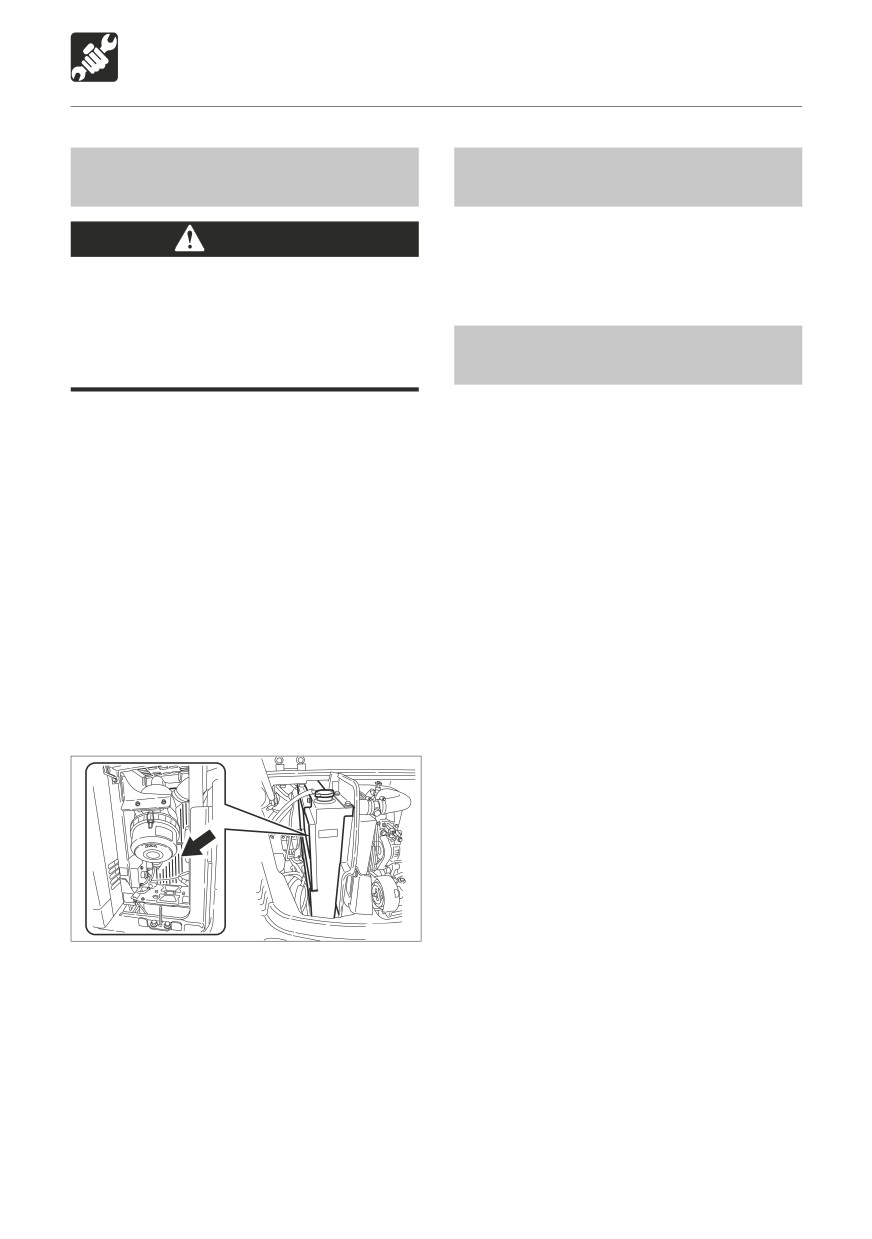
1. Open the left side cover and the engine
hood.
2. Blow compressed air on the radiator fins
and oil cooler fins to remove mud and dirt
stuck on them.
132
MAINTENANCE
Every 400 Hours
Inspecting the Transmission Gear
Inspecting the Differential Gear
Oil
Oil
WARNING
WARNING
Stop the engine and allow the machine
Stop the engine and allow the machine
to cool down before performing
to cool down before performing
maintenance.
maintenance.
• The transmission are hot directly after
• The differential are hot directly after
the engine is stopped. Touching them
the engine is stopped. Touching them
will cause burns.
will cause burns.
• The gear oil is also hot and under high
• The gear oil is also hot and under high
pressure.
pressure.
Be careful when loosening plugs.
Be careful when loosening plugs.
Working on the machine under these
Working on the machine under these
conditions could result in burns or
conditions could result in burns or
injuries.
injuries.
The pressure in the transmission
The pressure in the differential gears
reduction gears case may cause oil
case may cause oil or the plug to fly
or the plug to fly out. Loosen the plug
out. Loosen the plug slowly to release
slowly to release the pressure.
the pressure.
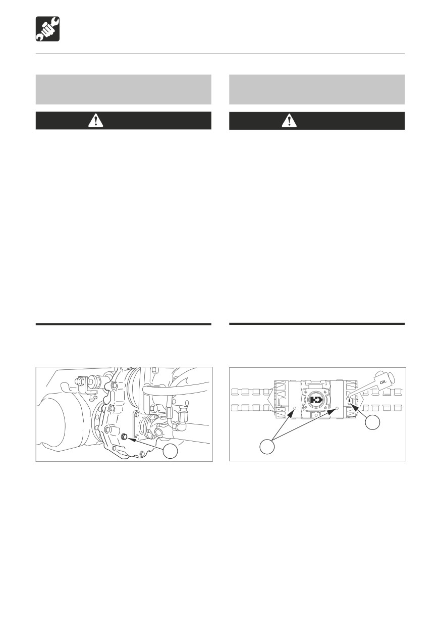
1. Park the machine on a level surface. Stop
1. Park the machine on a level surface. Stop
the engine.
the engine.
2
Oil level
1
1
Ölstand
W2G0161
W2G017
2. Remove the plug (1) from the transmission
2. Remove the plug (1) from the differential
housing.
housing.
3. If oil can be reached with the tip of the
3. If oil can be reached with the tip of the
your finger through the hole, the oil level
your finger through the hole, the oil level
is correct.
is correct.
4. If the level is low, add oil through the check
4. If the level is low, add oil through the add
plug hole until the oil flows from the hole.
plug hole (2) until the oil flows from the
5. Install and tighten the plug.
hole.
5. Install and tighten the plug.
133

MAINTENANCE
Every 400 Hours
Inspecting the Hub Gear Oil
WARNING
Stop the engine and allow the machine
to cool down before performing
maintenance.
• The hubs are hot directly after the
engine is stopped. Touching them will
cause burns.
• The gear oil is also hot and under high
pressure.
Be careful when loosening plugs.
Working on the machine under these
conditions could result in burns or
injuries.
The pressure in the hubs reduction
gears case may cause oil or the plug
to fly out. Loosen the plug slowly to
release the pressure.
1. Park the machine on a level surface. Stop
the engine.
2. Set the hub so that the plug (1) is at the
level.
1
W2G018
3. Remove the plug (1) from the hub
housing.
4. If oil can be reached with the tip of the
your finger through the hole, the oil level
is correct.
5. If the level is low, add oil through the check
plug hole until the oil flows from the hole.
6. Install and tighten the plug.
134
MAINTENANCE
Every 500 Hours
Replacing the Fuel Filter
Replacing the Water Separator
Filter
WARNING
WARNING
Do not smoke or permit open flames
while handling fuel or working on the
Do not smoke or permit open flames
fuel system.
while handling fuel or working on the
Stop the engine in a well-ventilated
fuel system.
place and allow it to cool down before
Stop the engine in a well-ventilated
performing maintenance.
place and allow it to cool down before
Clean up spilled fuel immediately.
performing maintenance.
Clean up spilled fuel immediately.
3
2
1
1
L7G030
L3G032
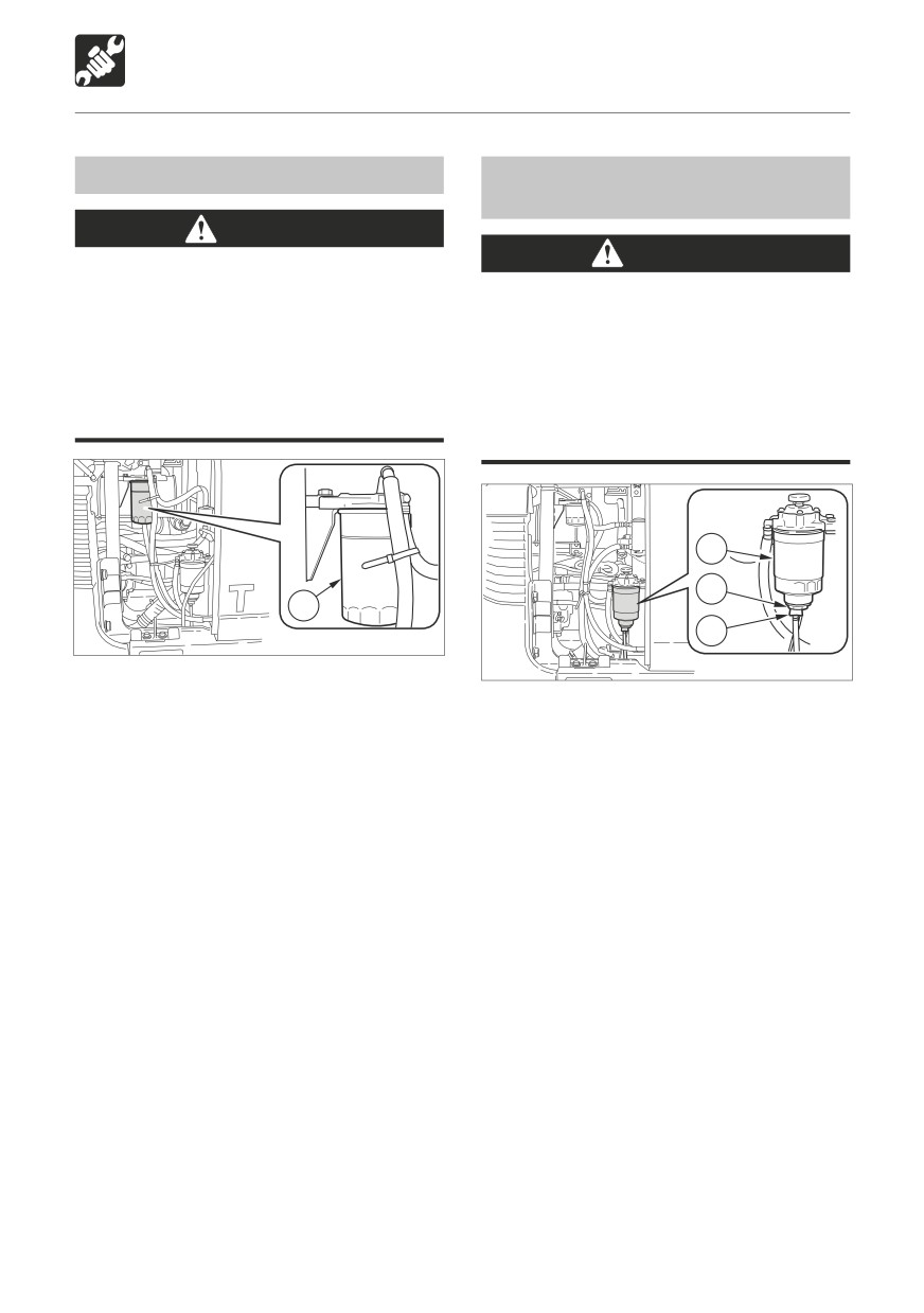
1. Open the right side cover.
2. Using a filter wrench, turn the filter (1)
1. Open the right side cover.
counterclockwise and remove it.
2. Place a pan under the drain hose.
3. Clean the surface of installation of the filter
3. Open the drain cock (1) and drain the
stand.
fuel.
4. Apply a thin layer of oil to the packing of
4. Remove the sensor (2).
the new filter.
5. Remove and discard the filter (3).
5. Install the new filter by hand.
6. Install the sensor (2) on the new filter.
6. Tighten 2/3 more turn with the filter wrench
7. Clean the surface of installation of the filter
after the filter packing comes in contact
stand.
with the surface of installation.
8. Apply a thin layer of oil to the packing of
7. Bleed the air.
the new filter.
Refer to page 157 “Bleeding the Air from
9. Install the new filter by hand.
the Fuel System”.
10. Tighten 2/3 more turn with the filter
wrench after the filter packing comes in
contact with the surface of installation.
11. Bleed the air.
Refer to page 157 “Bleeding the Air from
the Fuel System”.
135
MAINTENANCE
Every 500 Hours
Replacing the Hydraulic Oil
Return Filter
Refer to page 123 “Replacing the Hydraulic
Oil Return Filter”.
Replacing the Pilot Line Filter
Refer to page 126 “Replacing the Line
Filter”.
136
MAINTENANCE
Every 1000 Hours
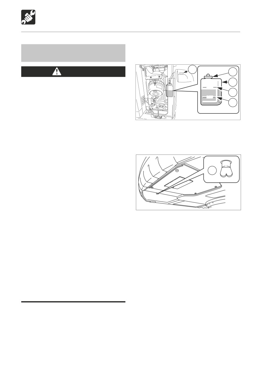
1. Open the left side cover and the engine
Cleaning the Engine Cooling
hood.
System
3
WARNING
2
Stop the engine and allow the machine
1
FULL
to cool down before performing
H
maintenance.
LOW
• The engine, muffler, radiator and many
L
other parts of the machine are hot
directly after the engine is stopped.
W3G010
Touching these parts will cause
burns.
2. Gradually loosen the radiator cap (3)
• The engine coolant is also hot and
to release the internal pressure, then
under high pressure. Be careful when
remove.
loosening caps and plugs. Working on
the machine under these conditions
could result in burns or injuries due
to the hot coolant spurting out.
4
If maintenance must be performed with
the engine running, always work as a
two person team with one person sitting
in the operator’s seat while the other
works on the machine.
L3G020
• When performing maintenance, be
sure to keep your body and clothing
3. Place a pan for catching the spent coolant
away from moving parts.
under the drain plug (4), then loosen the
Standing at the back of the machine
drain plug (4) and drain the coolant.
while the engine is running is extremely
4. Tighten the drain plug (4).
dangerous, as the machine could move
5. Add tap water through the radiator’s
suddenly. Never stand at the back of the
coolant supply port up to the top of the
machine while the engine is running.
port. Take your time doing this, adding the
Do not remove the radiator cap or drain
water slowly to avoid any air from entering
plugs when the coolant is hot. Stop the
the radiator.
engine, let the engine and radiator cool
6. Close the radiator cap (3).
and loosen the radiator cap or drain
7. Start the engine and run it at a speed
plugs slowly.
slightly above low idling. Raise the water
temperature to at least 90°C (194°F), then
When cleaning, if the temperature of the
run the engine for about 10 minutes with
coolant is low, the thermostat will be closed
the thermostat open.
and the coolant will not circulate in the
8. Stop the engine, let the water’s temperature
radiator. Heat the coolant water to at least
lower, then loosen the drain plug (4) and
90°C (194°F) before cleaning.
drain the water.
137
MAINTENANCE
Every 1000 Hours
9. After draining the water, clean using
Replacing the Air Cleaner
cleaning agent. Clean following the
Elements
instructions included with the cleaning
agent you are using.
WARNING
10. Repeat steps 4 to 8 to rinse the cooling
system.
Stop the engine and allow the machine
11. Tighten the drain plug (4).
to cool down before performing
12. Slowly add the new coolant (mixture of
maintenance.
antifreeze and tap water) through the
The engine, muffler, radiator and many
radiator’s coolant supply port up to the
other parts of the machine are hot
top of the port. Take your time doing
directly after the engine is stopped.
this.
Touching these parts will cause burns.
13. Close the radiator cap (3).
14. Warm up the engine. Use the meters to
IMPORTANT: Do not use an element if its
check that there are no irregularities in the
flutes, gaskets or seals are damaged.
cooling system at this time.
15. Raise the water temperature to at least
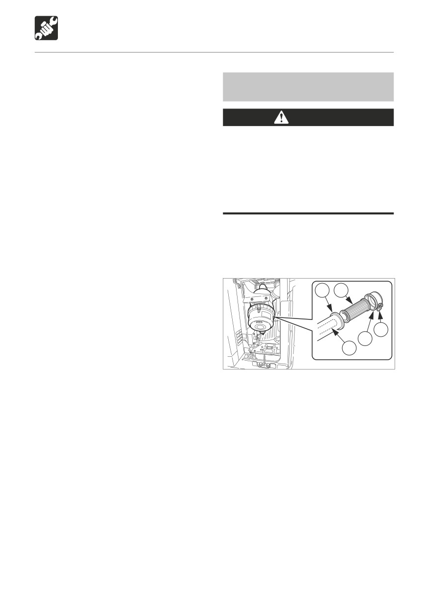
1. Open the left side cover.
90°C (194°F), then run the engine as such
for about 10 minutes.
16. Stop the engine, let the water’s temperature
4
3
lower, then check the level of coolant in
the radiator, and replenish up to the top
of the coolant supply port.
1
17. Close the radiator cap (3).
2
18. Clean the interior of the reserve tank (1),
5
then add coolant to the upper limit (H).
W3G050
19. After replacing the coolant, inspect the
coolant level once again after operating
2. Loosen the clamps (1) and remove the dust
the machine.
cup (2).
The coolant permeates the entire system
3. Clean the inside of the dust cup (2).
during operation, so the level decreases.
4. Remove the outer element (3).
Replenish by the amount the level has
Do not yet remove inner element (5).
decreased.
5. Clean the inside of the body (4).
6. Remove the inner element (5).
7. Install the new elements.
8. Install the dust cup (2) with the “TOP” mark
at the top, then fasten it with the clamps
(1).
138
MAINTENANCE
Every 1000 Hours
Replacing the Air Breather Filter
Inspecting and Adjusting the
Engine Valve Clearance
WARNING
This operation requires experience. Have
Never jump off the machine. Use the
it performed by a Takeuchi sales or service
steps and handrails when climbing on
outlet.
and off the machine, and always support
your body at three points with your
hands and feet.
Oil may spurt out if caps or filters are
Retightening the Engine Cylinder
removed or pipes disconnected before
Head Bolts
releasing the pressure in the hydraulic
This operation requires experience. Have
system.
it performed by a Takeuchi sales or service
• Gradually press the air breather button
outlet.
to relieve tank pressure.
N
A
B
H
J3G003
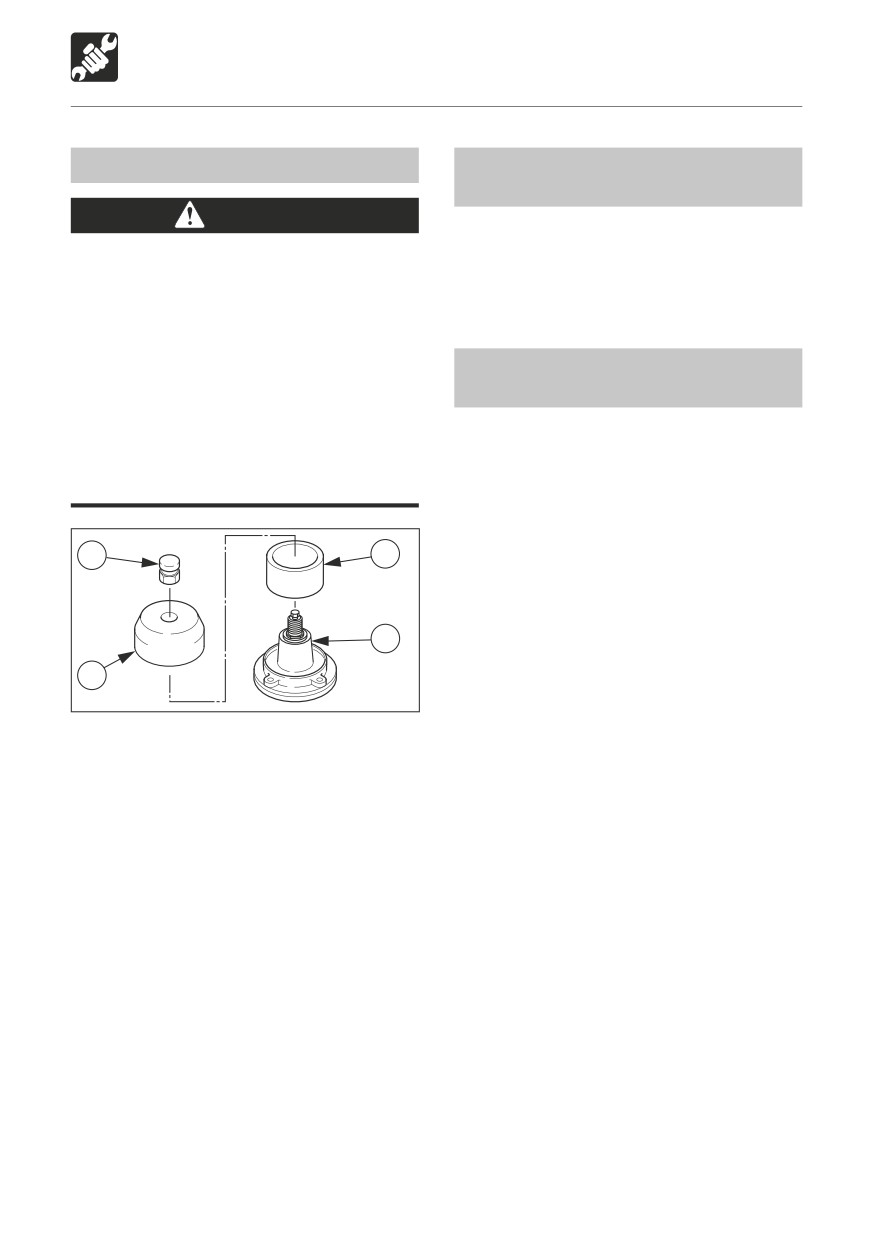
1. Press the button (N) and bleed the air from
the tank.
2. Remove the button (N) on the air
breather.
3. Remove cover (H).
4. Replace filter (A).
5. Install cover (H) on the body (B).
6. Install the button (N).
139
MAINTENANCE
Every 1500 Hours
Replacing the Transmission Gear
Replacing the Differential Gear
Oil
Oil
WARNING
WARNING
Stop the engine and allow the machine
Stop the engine and allow the machine
to cool down before performing
to cool down before performing
maintenance.
maintenance.
• The transmission are hot directly after
• The differential are hot directly after
the engine is stopped. Touching them
the engine is stopped. Touching them
will cause burns.
will cause burns.
• The gear oil is also hot and under high
• The gear oil is also hot and under high
pressure.
pressure.
Be careful when loosening plugs.
Be careful when loosening plugs.
Working on the machine under these
Working on the machine under these
conditions could result in burns or
conditions could result in burns or
injuries.
injuries.
The pressure in the transmission
The pressure in the differential gears
reduction gears case may cause oil
case may cause oil or the plug to fly
or the plug to fly out. Loosen the plug
out. Loosen the plug slowly to release
slowly to release the pressure.
the pressure.
1. Park the machine on a level surface. Stop
1. Park the machine on a level surface. Stop
the engine.
the engine.
2
Oil level
1
3
Ölstand
1
2
W2G0191
W2G020
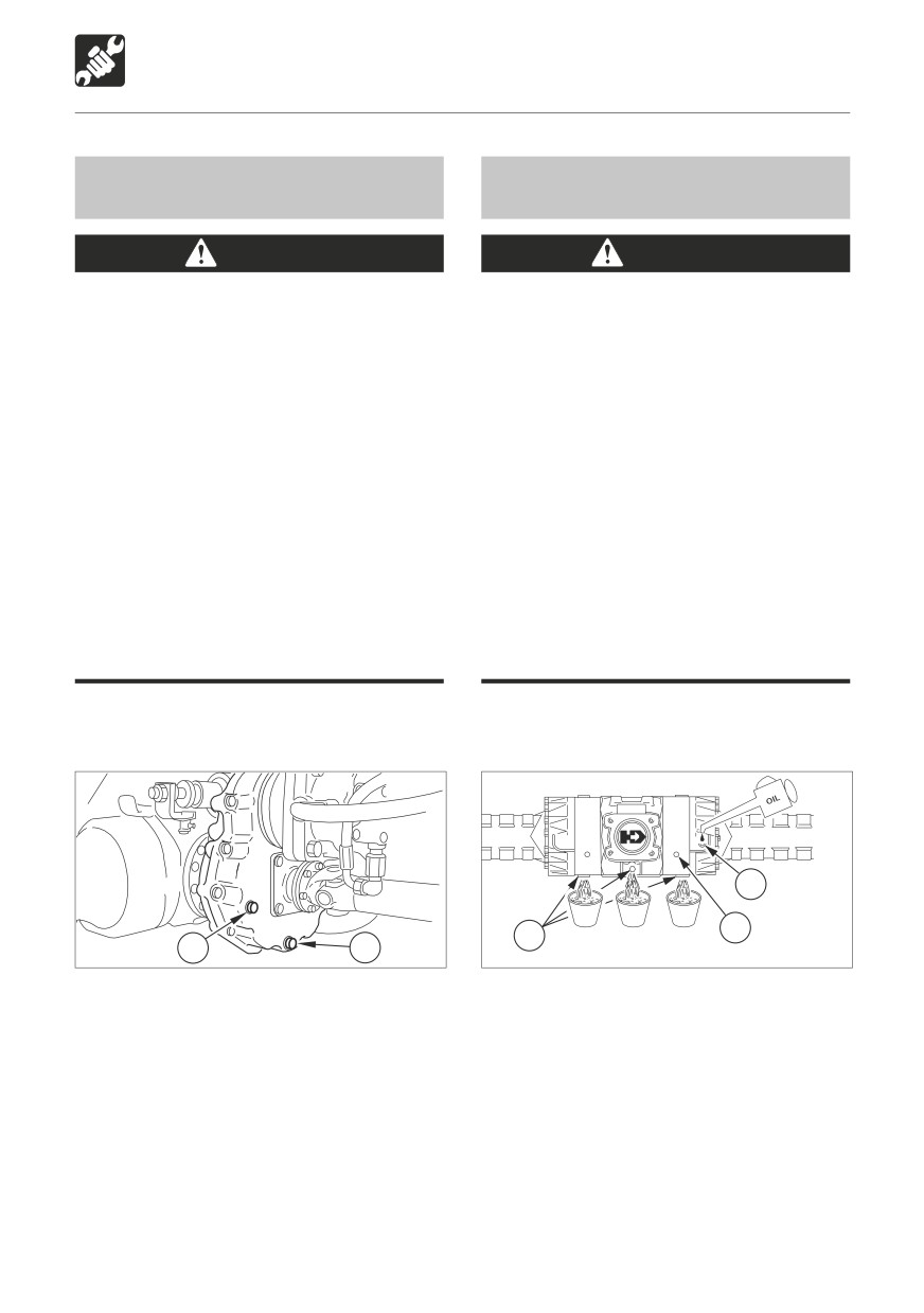
2. Place a pan for catching the spent oil under
2. Place a pan for catching the spent oil under
plug (2).
plugs (3).
3. Remove plug (2) and drain the oil.
3. Remove plugs (3) and drain the oil.
4. Tighten plug (2).
4. Tighten plugs (3).
5. Supply oil through the hole for plug (1) until
5. Supply oil through the hole for plug (2) until
oil flows out of the hole.
oil flows out of the hole (1).
6. Tighten plug (1).
6. Tighten plugs (1), (2).
140
MAINTENANCE
Every 1500 Hours
Replacing the Hub Gear Oil
WARNING
Stop the engine and allow the machine
to cool down before performing
1
maintenance.
• The hubs are hot directly after the
W2G018
engine is stopped. Touching them will
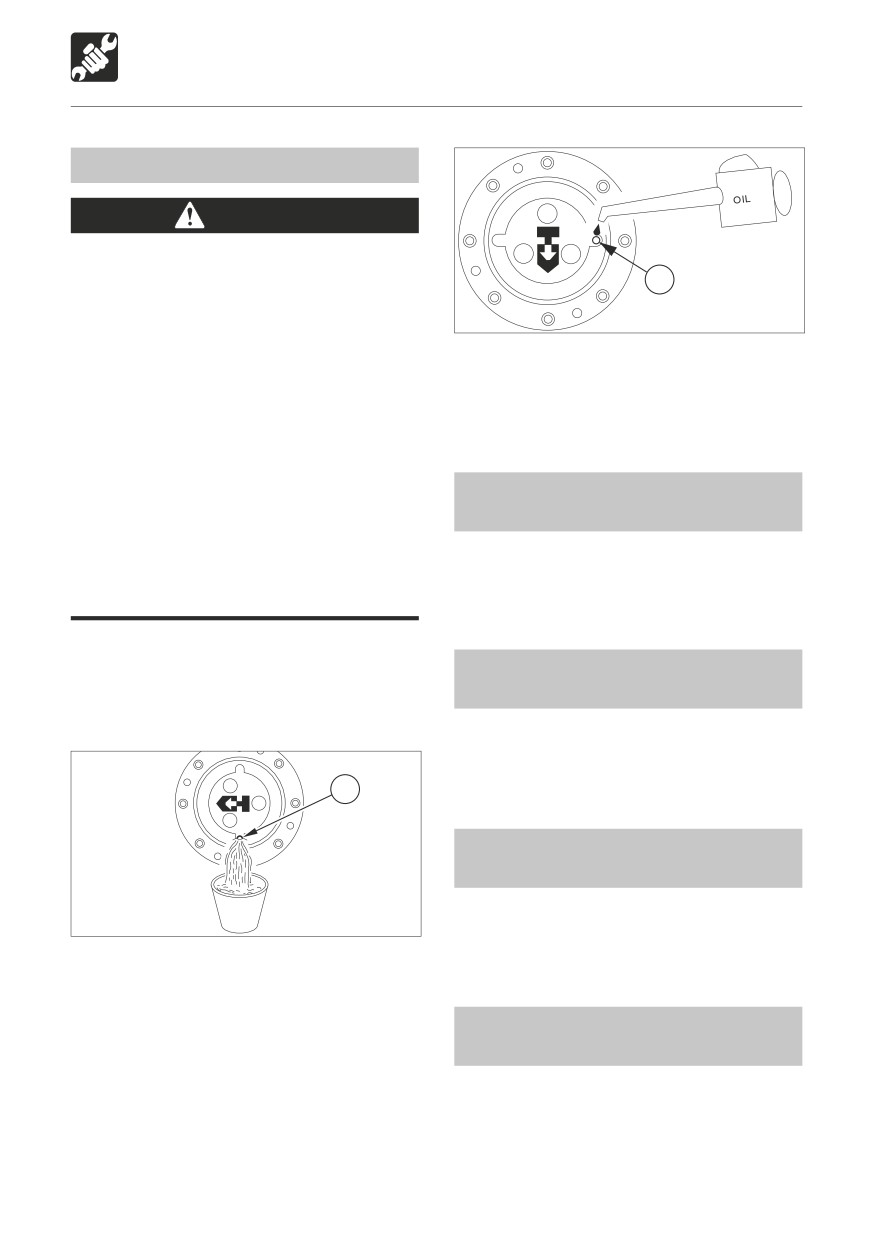
6. Supply oil through the hole for plug (1) until
cause burns.
oil flows out of the hole of plug (1).
• The gear oil is also hot and under high
7. Tighten plug (1).
pressure.
Be careful when loosening plugs.
Working on the machine under these
conditions could result in burns or
Inspecting and Cleaning the
injuries.
Engine Fuel Injectors
The pressure in the hubs reduction
gears case may cause oil or the plug
This operation requires experience. Have
to fly out. Loosen the plug slowly to
it performed by a Takeuchi sales or service
release the pressure.
outlet.
1. Set the hub so that the plug (1) is at the
very bottom.
Inspecting the Turbocharger
2. Park the machine on a level surface. Stop
(Blower wash as necessary)
the engine.
This operation requires experience. Have
it performed by a Takeuchi sales or service
outlet.
1
Inspecting and Cleaning the EGR
Valve, Lead Valve and Cooler
This operation requires experience. Have
W2G0211
it performed by a Takeuchi sales or service
outlet.
3. Place a pan for catching the spent oil under
plug (1).
4. Remove plug (1) and drain the oil.
Inspecting the Crankcase
5. Set the hub so that plug (1) is at the level.
Breather System
This operation requires experience. Have
it performed by a Takeuchi sales or service
outlet.
141
MAINTENANCE
Every 2000 Hours
Lapping the Engine Valve Seats
This operation requires experience. Have
it performed by a Takeuchi sales or service
outlet.
142
MAINTENANCE
Every 2000 Hours
Replacing the Hydraulic Oil and
4
Cleaning the Suction Strainer
10
1
5
WARNING
8
Stop the engine and allow the machine
9
to cool down before performing
maintenance.
• The engine, hydraulic lines and many
other parts of the machine are hot
6
directly after the engine is stopped.
Touching these parts will cause
burns.
• The hydraulic fluid is also hot and
under high pressure.
7
Be careful when loosening caps and
L7G020
plugs. Working on the machine under
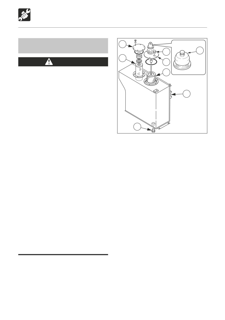
2. Press button (1) and release the pressure
these conditions could result in burns
in the tank.
or injuries due to the hot oil spurting
3. Replace the air breather filter (A).
out.
Refer to page 139 “Replacing the Air
Never jump off the machine. Use the
Breather filter”.
steps and handrails when climbing on
4. Remove the plug (10).
and off the machine, and always support
5. Loosen the bolts, and remove the flange
your body at three points with your
(4).
hands and feet.
6. Remove the return filter (5).
Oil may spurt out if caps or filters are
7. Place a pan for catching the spent oil under
removed or pipes disconnected before
the drain plug (7).
releasing the pressure in the hydraulic
8. Loosen the drain plug (7) and drain the
system.
hydraulic oil.
• Gradually press the air breather button
9. Loosen the bolts, and remove the flange
to relieve tank pressure.
(8).
• When removing plugs or screws or
10. Remove the suction strainer (9) and clean
disconnecting hoses, stand to the
it.
side and loosen slowly to gradually
11. Clean the inside of the hydraulic tank.
release the internal pressure before
12. Install the new return filter and suction
removing.
strainer (9).
13. Install the flanges (4) and (8).
1. Slew 45° clockwise and set the machine to
14. Tighten the drain plug (7).
the hydraulic oil level inspection posture.
15. Supply hydraulic oil up to the middle of
Refer to page 118 “Inspecting the Hydraulic
the sight gauge (6) from the hole of plug
Oil Level and Replenishing”.
(10).
16. Tighten the plug (10).
143
MAINTENANCE
Every 2000 Hours
17. Follow the procedure next “Bleeding the
Slew motor
air” to bleed the air from the hydraulic oil
circuit.
18. Set the machine to the hydraulic oil
level inspection posture and inspect the
level once the temperature of the oil has
dropped.
Refer to page 118 “Inspecting the
Hydraulic Oil Level and Replenishing”.
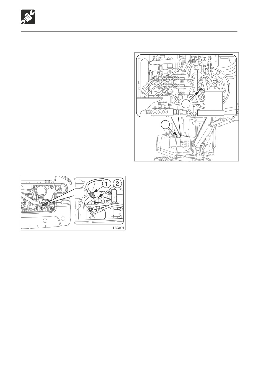
2
Bleeding the air
1
IMPORTANT: After replacing the hydraulic
oil, bleed the air from the hydraulic circuit
and hydraulic devices. Failure to do so
may damage the hydraulic devices.
W2G022
Hydraulic pump
1. Loosen the bolts and remove the center
cover (1).
2. Remove the plug (2).
3. Once hydraulic oil overflows from the plug
hole, tighten the plug (2).
4. Install the center cover (1).
Cylinders
1. Start the engine and run it at low idle for
10 minutes.
1. Open the engine hood.
2. Set the engine to a low idle, then extend
2. Disconnect the drain hose (1) from the
and contract all the cylinders 4 or 5 times,
hydraulic pump.
without going to the stroke end.
3. Once hydraulic oil overflows from the
3. Run the engine at high speed, then extend
elbow (2), connect the drain hose (1).
and contract all the cylinders 4 or 5 times,
without going to the stroke end.
4. Set the engine back to a low idle, then
extend and contract all the cylinders 4 or
5 times to the stroke ends.
144
MAINTENANCE
When Required
3. Remove the key, then check that the
Replacing the Bucket Teeth and
bucket is stable.
the Side Cutters
Replace the bucket teeth and the side cutters
when the tooth points or the side cutters are
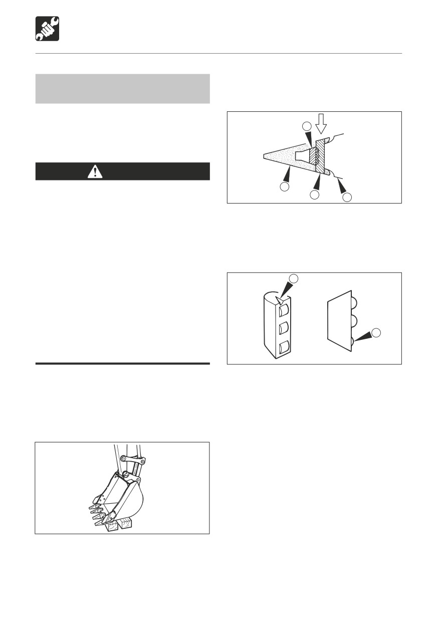
3
worn, before the adapter or the bucket is
damaged.
WARNING
2
Before performing maintenance or
1
4
E4G043
repairs under the machine, set all
working equipment against the ground
4. Remove locking pin (1) and remove point
or in the lowermost position.
(2).
To prevent unexpected movement,
5. Take out rubber pin lock (3) and check
securely block the working elements
whether it is still usable.
when repairing or replacing the bucket
teeth and the side cutters.
E
Wear required appropriate equipment
such as safety glasses when using
hammers, as metal fragments or other
objects can fly and cause serious
personal injury.
F
Do not allow unauthorized personnel in
the work area.
E4G044
E
When these are cracks in the rubber
Bucket tooth
and it seems like the roller is about to
Removal
come off.
1. Clean the bucket and park the machine in a
F
When the roller becomes dented
flat, safe place where the ground is hard.
when pressed with a finger.
E4G042
2. Set the bottom surface of the bucket flat
and lower it on a block so that the locking
pin can be knocked out.
145
MAINTENANCE
When Required
Installation
Side cutter
Installation
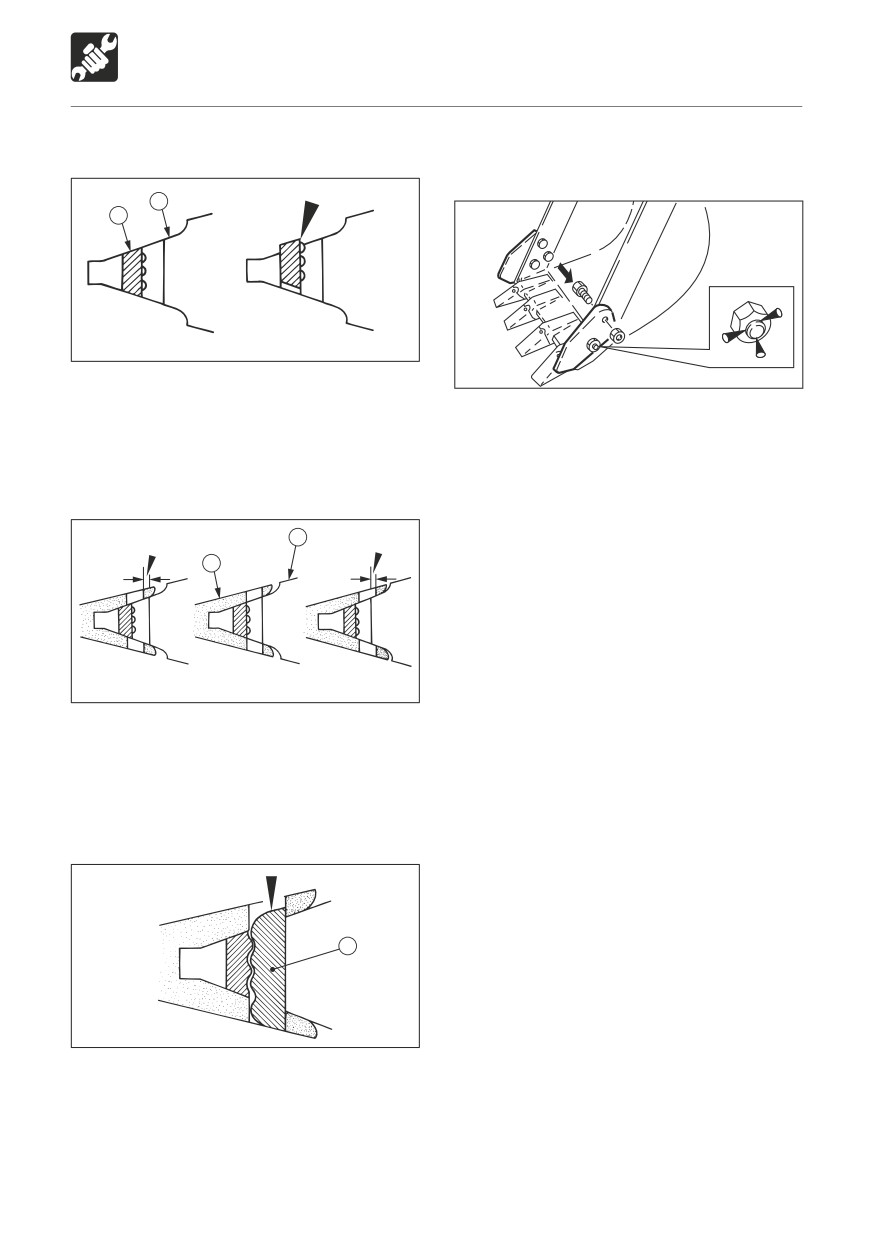
4
3
E4G045
G4G026
1. Push rubber pin lock (3) into welding
adaptor (4).
1. Insert the bolts from the inner of the bucket
and tighten the nuts.
Do not let the rubber pin lock stick out past
• Tightening torque: 475 N·m (350 ft-lb)
the welding adapter surface.
2. Caulk the bolts with a punch at three spots
along the periphery of the screw to prevent
the nuts from coming loose.
Improper
Proper
4
Proper
2
E4G046
2. Install point (2) onto welding adaptor (4).
Insert the point so that the surface behind
the point’s pin hole is flush or deeper than
the surface behind the welding adapter’s
pin hole.
1
E4G047
3. Drive in locking pin (1).
After driving in the locking pin, use a pin with
the same surface as the point surface. Do not
use worn locking pins.
146
MAINTENANCE
When Required
Adjusting the gap between the
bucket and arm
WARNING
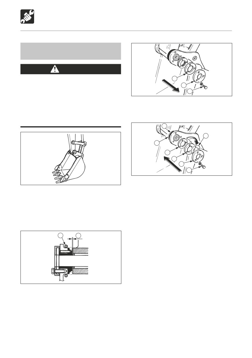
4
Before performing maintenance or
3
repairs under the machine, set all
2
working equipment against the ground
E4G050
or in the lowermost position.
4. Remove the three bolts (2), the end plate
To prevent unexpected movement,
(3) and flange (4).
securely block the working equipment
when adjusting.
1
5
A
5
4
3
2
E4G051
E4G048
5. Extract adjustment shim (5) from between
flange (4) and the bucket body according
1. Ground the bucket as shown on the
to gap (A).
diagram above in a stable position.
Adjustment shim thickness : 0.5 mm (0.02
2. Check that the bucket dose not move,
in.)
then set the safety lock lever to the locked
Be careful that the gap is no less than 0.5
position and stop the engine.
mm (0.02 in.) after adjustment.
Note: Example (for a gap of 2 mm or 0.08
1
A
in.)
2 mm - 0.5 mm (standard value)
= 1.5 mm (0.06 in)
In the above example, three shims (5) should
be removed.
6. Insert adjustment shim (5) removed in
E4G049
step 5 above between end plate (3) and
flange (4) and fasten it in place with the
3. Slide the O-ring (1) to bring the gap (A) into
three bolts (2).
view and measure the width of the gap
• Tightening torque for bolts (2)
(A).
83.4 N·m (61.5 ft-lb.)
The gap (A) should be 0.5 mm (0.02 in.)
7. Return the O-ring (1) to their original
Swing the bucket slightly to the left and
position.
lightly press the arm point to the left side of
the bucket (the side without an adjuster).
147
MAINTENANCE
When Required
Inspecting and Replenishing the
Draining the Water Separator
Windshield Washer Fluid
WARNING
Use a windshield washer fluid designed
specifically for motor vehicles. Follow the
Do not smoke or permit open flames
instructions including with the washer fluid.
while handling fuel or working on the
fuel system.
Stop the engine in a well-ventilated
place and allow it to cool down before
2
performing maintenance.
Clean up spilled fuel immediately.
1
G4G030
3
Inspection
2
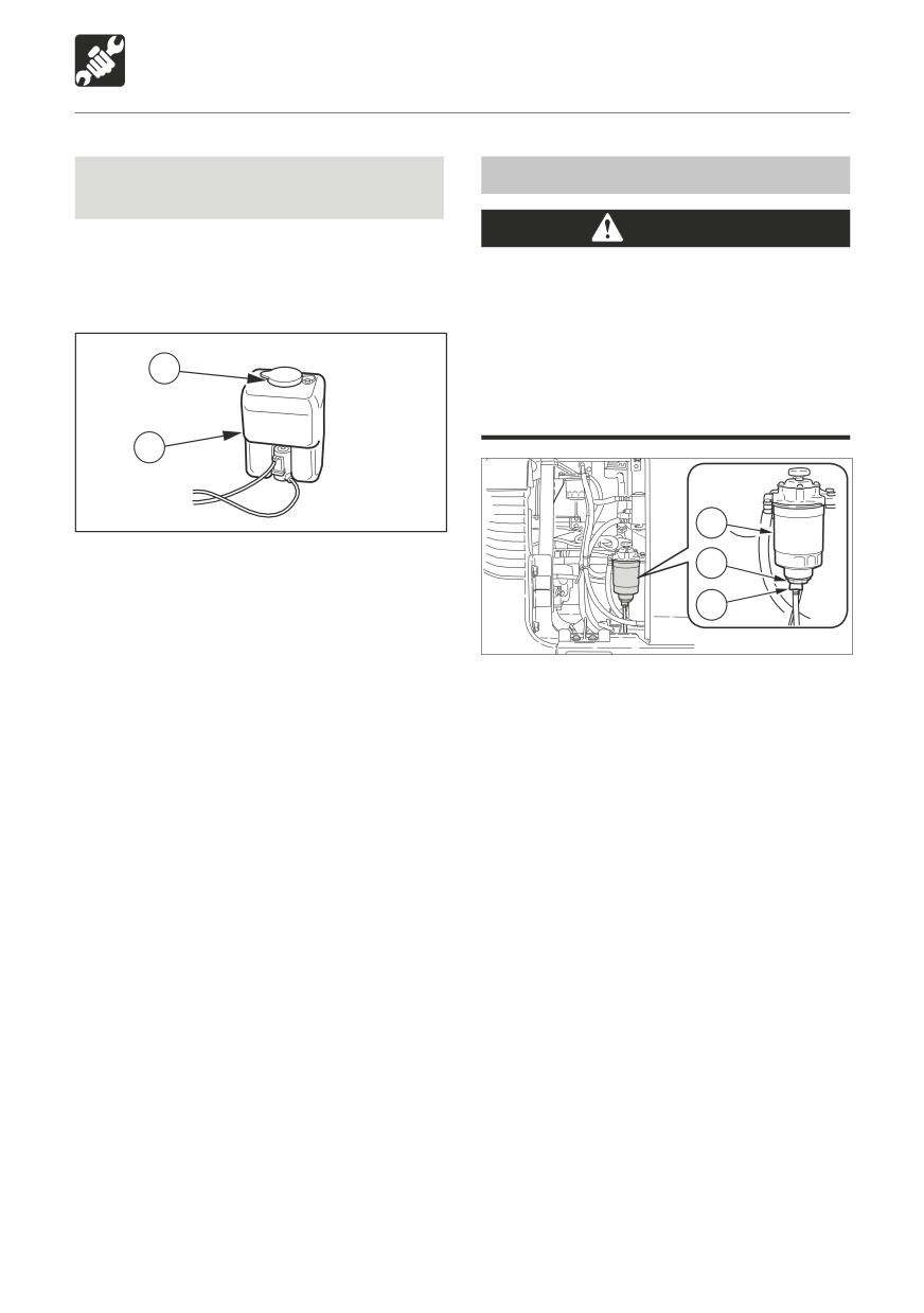
1. Open the cab door.
2. Inspect the washer tank (1) and add washer
1
fluid if the level is low.
L3G032
Replenishment
1. Open the right side cover.
1. Mix the washer fluid to the prescribed
2. Place a pan under the drain hose.
concentration.
3. Open the drain cock (1) and drain the
2. Remove the cap (2) and add washer
water.
fluid.
4. Close the drain cock (1).
3. Reinstall the cap (2).
Bleeding the air from the fuel system
Refer to page 157 “Bleeding the Air from the
Fuel System”.
Supplement: Air in the fuel system can make
it difficult to start the engine and cause engine
problems. Also bleed the air when the fuel
tank is emptied.
148
MAINTENANCE
When Required
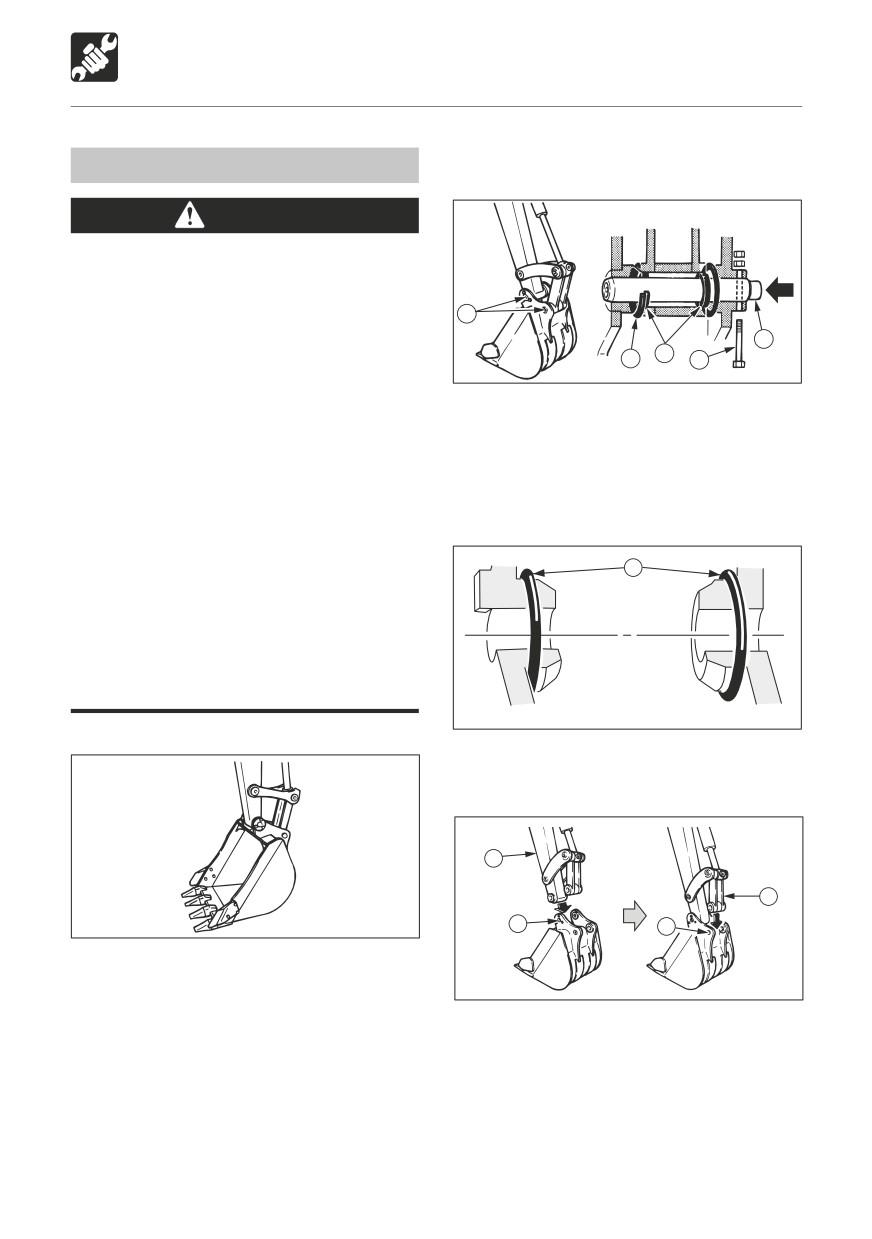
3. Remove the bolt (1).
Replacing the Bucket
WARNING
Before performing maintenance or
repairs under the machine, set all
working equipment against the ground
5
or in the lowermost position.
If maintenance must be performed with
2
4
3
1
the engine running, always work as a
E4G052
two person team with one person sitting
in the operator’s seat while the other
4. Hammer pin (2) out of the bucket.
works on the machine.
5. Remove the bucket.
• When performing maintenance, be
Inspect the pin seal (3) and replace it if it is
sure to keep your body and clothing
deformed or damaged. (See next page.)
away from moving parts.
Wear required appropriate equipment
Installation
such as safety glasses and filter
4
mask when using hammers, as metal
fragments or other objects can fly and
cause serious personal injury.
When lining up the pin holes, always do
so by sight. Your finger may be cut off
if you stick it into the hole.
E4G053
Removal
1. Set the bucket’s O-ring (4) as shown on the
diagram.
5
6
E4G048
A
B
1. Ground the bucket as shown on the
diagram above in a stable position.
E4G054
Supplement: When removing pins, set the
bucket so that it is just gently against the
2. Line up pin hole (A) in the bucket with the
ground. If it is strongly against the ground, the
pin hole in the arm (5), and install the pin
resistance will be great and it will be difficult
(2).
to remove the pin.
3. Operate the cylinder, line up pin hole (B) in
2. Set the safety lock lever to the locked
the bucket with the pin hole in the link arm
position and stop the engine.
(6), and install the pin (2).
149
MAINTENANCE
When Required
1
0.5~1mm
E4G055
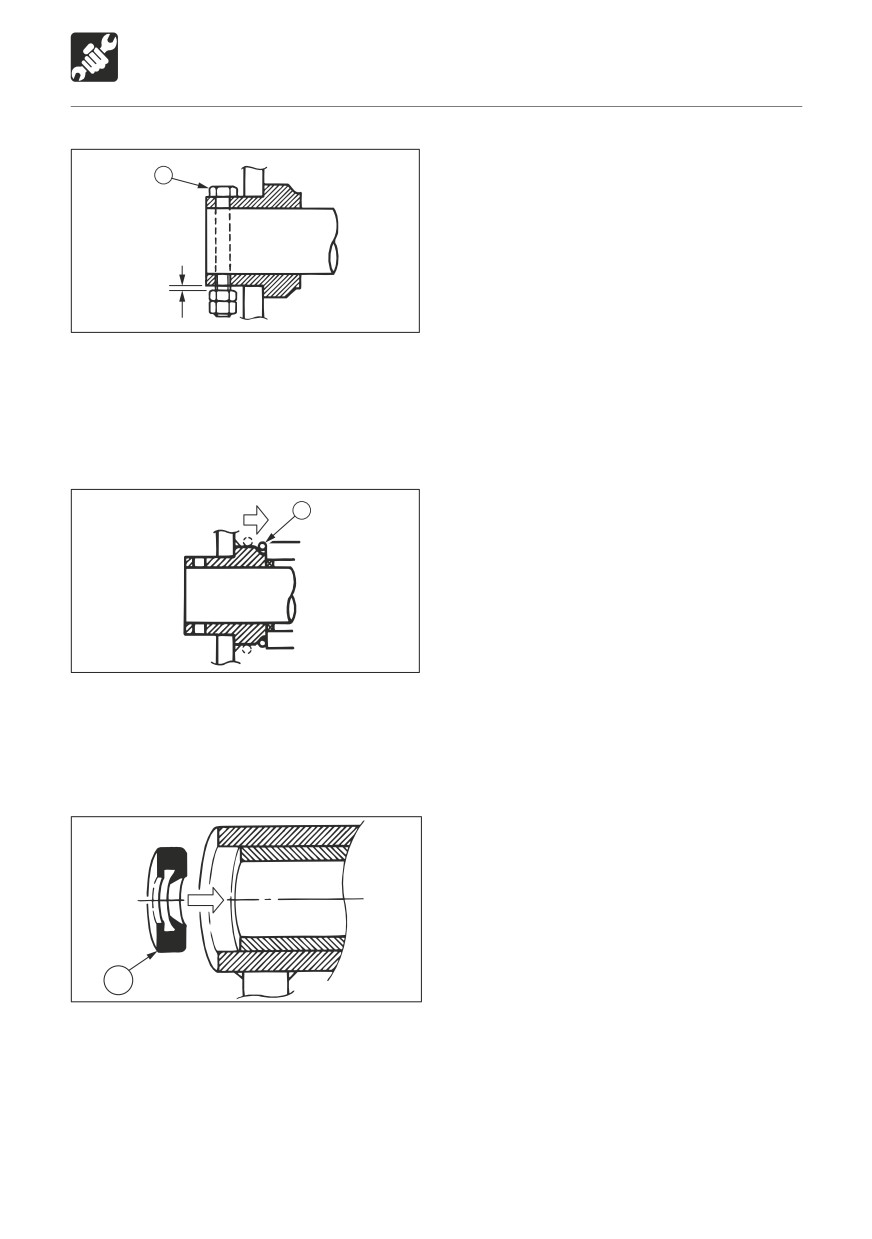
4. Line up the turn prevention holes, install
the bolt (1), and the nuts.
Be sure to leave a gap of about 0.5 ~ 1
mm (0.02 ~ 0.04 in.) between the nut and
bucket bush, or the nut will come loose.
4
E4G056
5. Adjust the gap between the bucket and
the arm. Refer to page 145.
6. Slide the O-ring (4).
Replacing the pin seal
3
E4G057
1. Set the pin seal (3) in the direction shown
on the diagram above.
2. Use a mallet to slowly press the pin seal
in. Be careful not to damage the seal.
150
MAINTENANCE
When Required
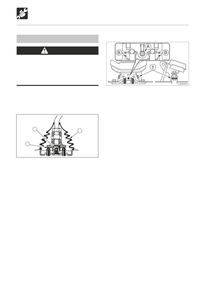
Boom swing pedal
Lubricating the Levers
WARNING
Set the machine to the parking posture,
stop the engine, remove the starter key
and store it. Failure to do so may result in
the machine moving abruptly, leading to
serious injury or death.
If the levers or pedals no longer move
1. Remove the lower mount section of the
smoothly, supply grease.
boot (1) and turn it upwards.
2. Wipe off the old grease.
Operating levers
3. Supply grease to points (A) and (B).
4. Set the boot (1) back as it was.
A
1
B
E4G058
1. Remove the lower mount section of the
boot (1) and turn it upwards.
2. Wipe off the old grease.
3. Supply grease to points (A) and (B).
4. Set the boot (1) back as it was.
151
MAINTENANCE
Long-term Storage
Procedures for storage
During storage
If the machine is to be stored for 30 days or
more, store it indoors. If it must be stored
WARNING
outdoors, stop it on wood laid out on a flat
surface and place a waterproof cover over it
Do not operate the engine in an enclosed
so that it stays dry.
area without adequate ventilation.
1. Clean the machine.
If natural ventilation is poor, install
2. Inspect for oil leakage, water leakage and
ventilators, fans, exhaust extension
loose nuts and bolts.
pipes or other artificial venting
3. Add fuel and replace the hydraulic oil and
devices.
oil.
4. To prevent rusting and freezing, replace
1. To prevent rusting, operate the machine
the engine coolant with long-life coolant
once a month so that the oil is fully
(LLC).
circulated.
Refer to page 137 “Cleaning the Engine
2. Inspect the battery and recharge it if
Cooling System”.
necessary.
5. Use the grease gun to supply grease to the
Have the battery charged by a Takeuchi
grease nipples.
sales or service outlet.
6. Fully contract the bucket and arm cylinders
and ground the bucket and dozer blade.
Starting the machine after storage
7. Apply rust-prevention oil to the hydraulic
cylinder rods.
IMPORTANT: If the “Procedures for
8. Disconnect the cable from the battery’s
storage” have not been performed and the
“-” terminal and cover the battery to
machine has been stored for a long period
prevent freezing.
of time, consult a Takeuchi sales or service
outlet before reusing the machine.
1. Wipe off the rust-prevention oil that was
applied to the hydraulic oil cylinders’ piston
rods.
2. Add fuel, oil and grease to all parts.
152
TROUBLESHOOTING
Symptoms that are not Malfunctions
154
If the Engine Overheats
155
If the Battery Goes Dead
156
After the Fuel Runs Out
157
If a Fuse Blows
158
If a Warning Lamp Flashes
160
Other Symptoms
162
To Lower the Boom
164
Towing
165
153
TROUBLESHOOTING
Symptoms that are not Malfunctions
The following symptoms are not
Performance decreases when an
malfunctions:
attachment weighing more than a standard
arm or bucket is mounted.
E4J001
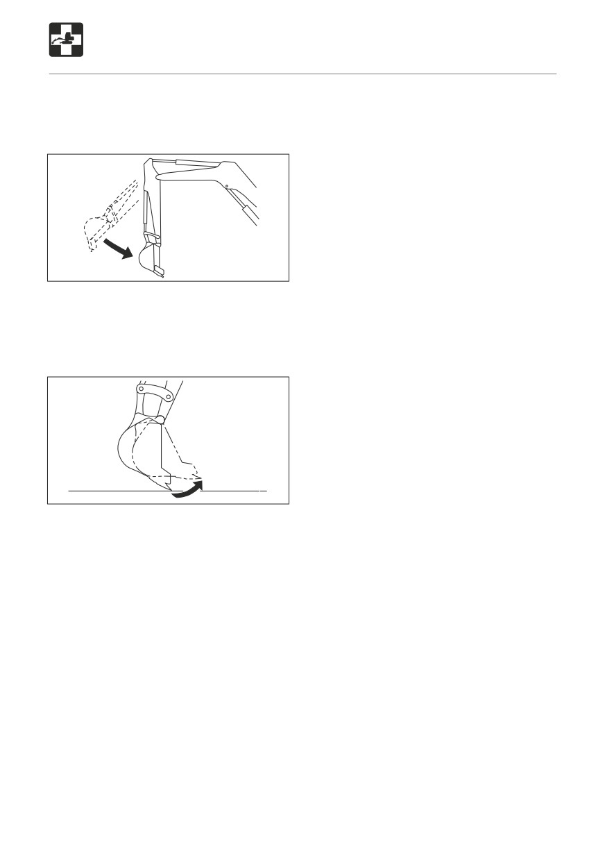
When the arm reaches the vertical position
while contracting it while the engine is
running at low speed, the contracting
speed slows down momentarily.
E4J002
When the bucket teeth reach the horizontal
position while the engine is running at low
speed, the speed of bucket movement
slows down momentarily.
The slew motor produces noise at
the beginning and end of the slewing
operation.
The travel motor produces noise when
stopped suddenly during high speed
travel.
The control valve produces noise if
excessive force is applied to the working
equipment and when the stroke end is
reached.
154
TROUBLESHOOTING
If the Engine Overheats
Procedure
WARNING
1. Park the machine in a safe place.
Do not open the engine hood when there
2. Inspect whether the coolant temperature
is steam coming from the engine room.
warning lamp is flashing or if there is
The steam or hot water may spurt out,
steam coming out when the engine hood
resulting in burns.
is closed.
Do not remove the radiator cap or drain
3. If there is steam, stop the engine
plugs when the coolant is hot. Stop the
immediately and contact a Takeuchi sales
engine, let the engine and radiator cool
or service outlet for repairs.
and loosen the radiator cap or drain
If the coolant temperature warning lamp
plugs slowly.
is off, run the engine at low idle and let the
Stop the engine and allow the machine to
water temperature decrease.
cool down before performing inspection
4. Once the water temperature gauge drops
and maintenance.
to the green zone, stop the engine.
5. Once the engine is cool, perform the
The following symptoms indicate
following inspections and procedures:
overheating:
• Fan belt slack
Adjust.
Refer to page 125.
• Coolant level
Add.
Refer to page 116.
• Water leakage
Repair.
• Radiator fins
Clean.
Refer to page 132.
• Sediment in cooling system
Clean.
Refer to page 137.
If the problem persists after the above
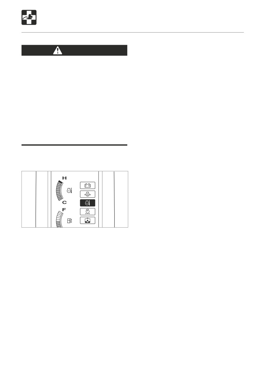
L7J0101
procedures are taken, contact a Takeuchi
An alarm is sounded and the coolant
sales or service outlet for repairs.
temperature warning lamp flashes.
The water temperature gauge is in the red
zone.
The engine slows down and the force
decreases.
Steam comes from the engine room.
155
TROUBLESHOOTING
If the Battery Goes Dead
The following symptoms indicate that the
Connecting the jumper cables
battery is dead:
The starter motor does not turn or turns
IMPORTANT: Set the starter keys of both
weakly, and the engine does not start.
the rescue vehicle and problem vehicle to
The horn is weak.
the OFF position.
Procedure
Rescue vehicle battery
Problem vehicle battery
Use jumper cables and start the engine using
2
1
the rescue vehicle’s battery.
R
WARNING
Use jumper cables only in the
3
To engine block
B
recommended manner. Improper use
4
E4J005
of jumper cables can result in battery
explosion or unexpected machine
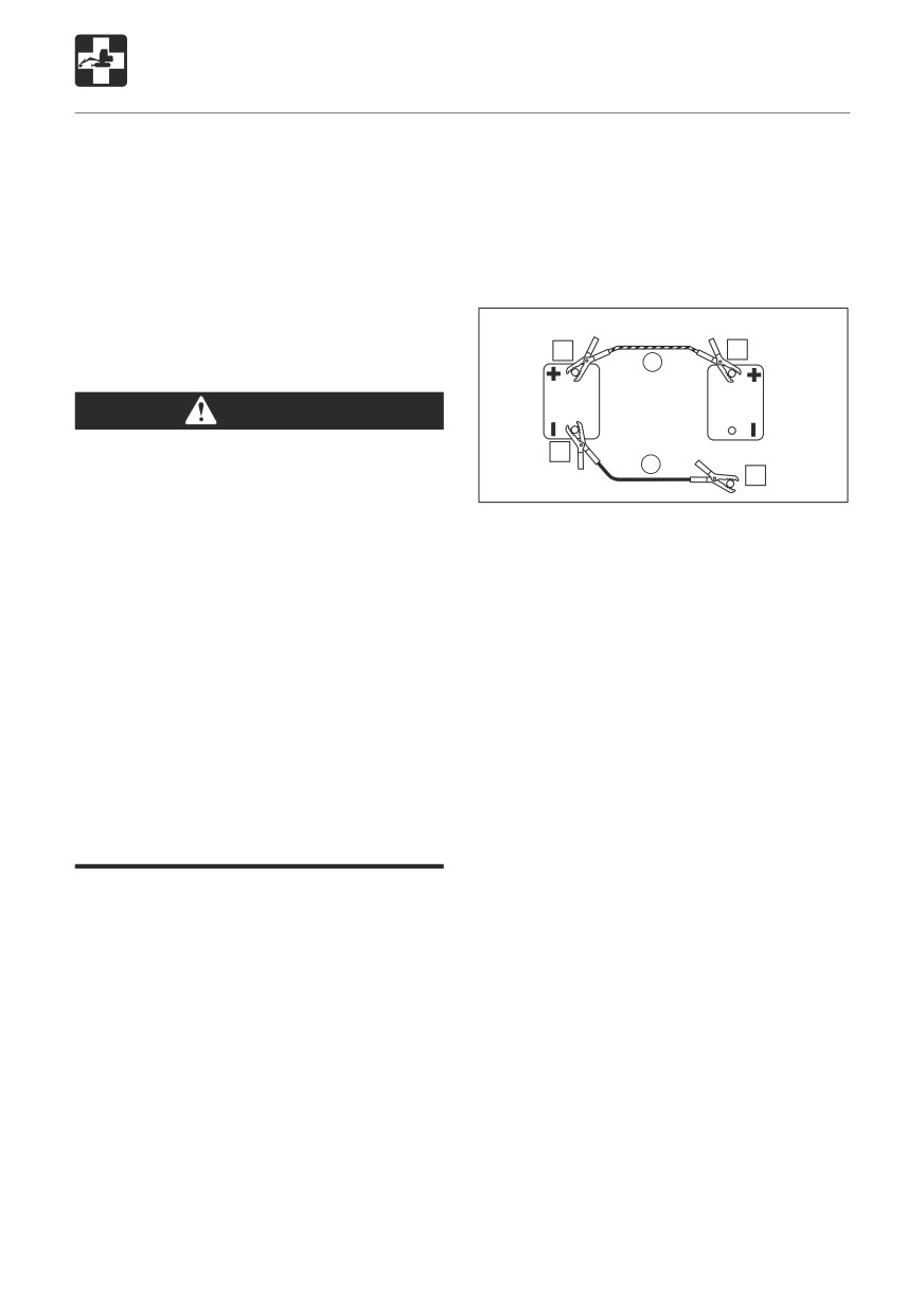
1. Connect the clip of jumper cable (R) to the
motion.
problem vehicle’s “+” terminal.
• Do not let the problem vehicle and
2. Connect the other clip of jumper cable (R)
rescue vehicle touch each other.
to the rescue vehicle’s “+” terminal.
• Do not let the “+” and “-” clips of the
3. Connect the clip of jumper cable (B) to the
jumper cables touch each other.
rescue vehicle’s “-” terminal.
• Connect the jumper cables to the “+”
4. Connect the other clip of jumper cable
terminals first, and disconnect them
(B) to the problem vehicle’s engine block.
from the “-” terminals (ground) first.
Connect the clip as far from the battery as
• Connect the final clip of the jumper
possible.
cable to a point as far away from the
battery as possible.
Starting the engine
Use safety glasses when using jumper
1. Check that the clips are securely connected
cables to start the machine.
to the terminals.
2. Start the rescue vehicle’s engine and run
it at high speed.
IMPORTANT: Use jumper cables and clips
3. Start the problem vehicle’s engine.
of a size suited to the battery’s capacity.
Do not used damaged or corroded jumper
cables and clips.
IMPORTANT: The rescue vehicle’s battery
must have the same capacity as the
problem vehicle’s battery.
IMPORTANT: Connect the clips securely.
156
TROUBLESHOOTING
If the Battery Goes Dead
After the Fuel Runs Out
Disconnecting the jumper cables
Bleeding the Air from the Fuel
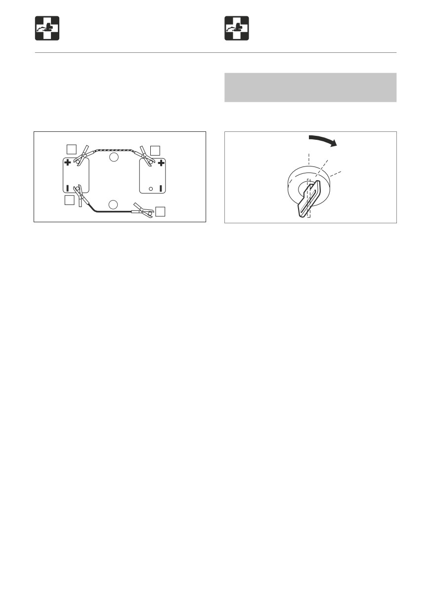
Once the engine starts, disconnect the jumper
System
cables following the connection procedure in
reverse order.
1. Add fuel.
Rescue vehicle battery
Problem vehicle battery
3
OFF
4
ON
R
START
2
From engine block
B
1
E4J006
L3D001
1. Disconnect the clip of jumper cable (B)
2. Turn the starter key to the ON position and
from the problem vehicle’s engine block.
hold it there for about 20 seconds.
2. Disconnect the other clip of jumper cable
The automatic air bleeder bleeds the air
(B) from the rescue vehicle’s “-” terminal.
from the fuel system.
3. Disconnect the clip of jumper cable (R)
from the rescue vehicle’s “+” terminal.
Supplement: Air in the fuel system can make
4. Disconnect the other clip of jumper
it difficult to start the engine and cause engine
cable (R) from the problem vehicle’s “+”
problems. Also bleed the air when the fuel
terminal.
tank is emptied.
Recharging
Have a Takeuchi sales or service outlet
recharge batteries that have gone dead.
157
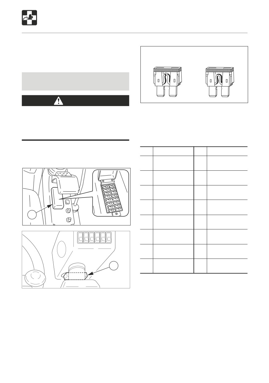
TROUBLESHOOTING
If a Fuse Blows
If a light does not turn on or the electric
system does not operate, a fuse may be
Blown
Normal
blown. Inspect the fuses.
Inspecting and Replacing the
Fuse
E4J007
WARNING
4. If a fuse is blown, replace it with a spare
If the fuse blows as soon as it is replaced,
fuse of the same capacity.
there is a problem with the electric system.
Continued use may lead to fire. Consult a
Takeuchi sales or service outlet.
Fuse Layout and Circuits Protected (1)
1. Turn the starter key to the OFF position and
Capacity
Protected circuit
Capacity
Protected circuit
stop the engine.
5A
Starter switch
10A
Turn signal
10A
Solenoid
10A
Lever lock
(Opt.)
10A
Wiper,
5A
Instrument
Radio
cluster
30A
Air conditioner
10A
Solenoid
(Opt.)
1
10A
Option
10A
T-ECU
L3J002
30A
F. S. pump
10A
Sensor
5A
Horn,
5A
Feed Pump
Radio (B)
10A
T-ECU (B)
5A
E-ECU (IG)
2
W2J0011
2. Open the fuse box cover (1) or (2).
3. Inspect for any blown fuses.
158
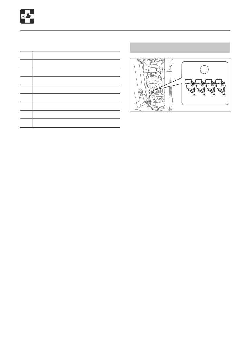
TROUBLESHOOTING
If a Fuse Blows
Fuse Layout and Circuits Protected (2)
Inspecting the Fusible Link
Capacity
Protected circuit
10A
Hazard, Turn signal
1
10A
Buzzer
5A
Parking lights (R.H.)
5A
Parking lights (L.H.)
10A
Head lights (R.H.)
10A
Head lights (L.H.)
W3J010
5A
Reserve
If the power is not switched on after
turning the starter switch to the ON
10A
Reserve
position, the cartridge type fusible links
(1) might be blown open. Open the left
side cover and inspect. If the fusible link
is blown, please contact your dealer.
Supplement: A fusible link is a large piece
of fuse wiring which is mounted in a circuit
which carries a large electrical current. Link
a regular fuse, the fusible link protects the
electrical parts and wiring from damage due
to abnormally large currents.
159
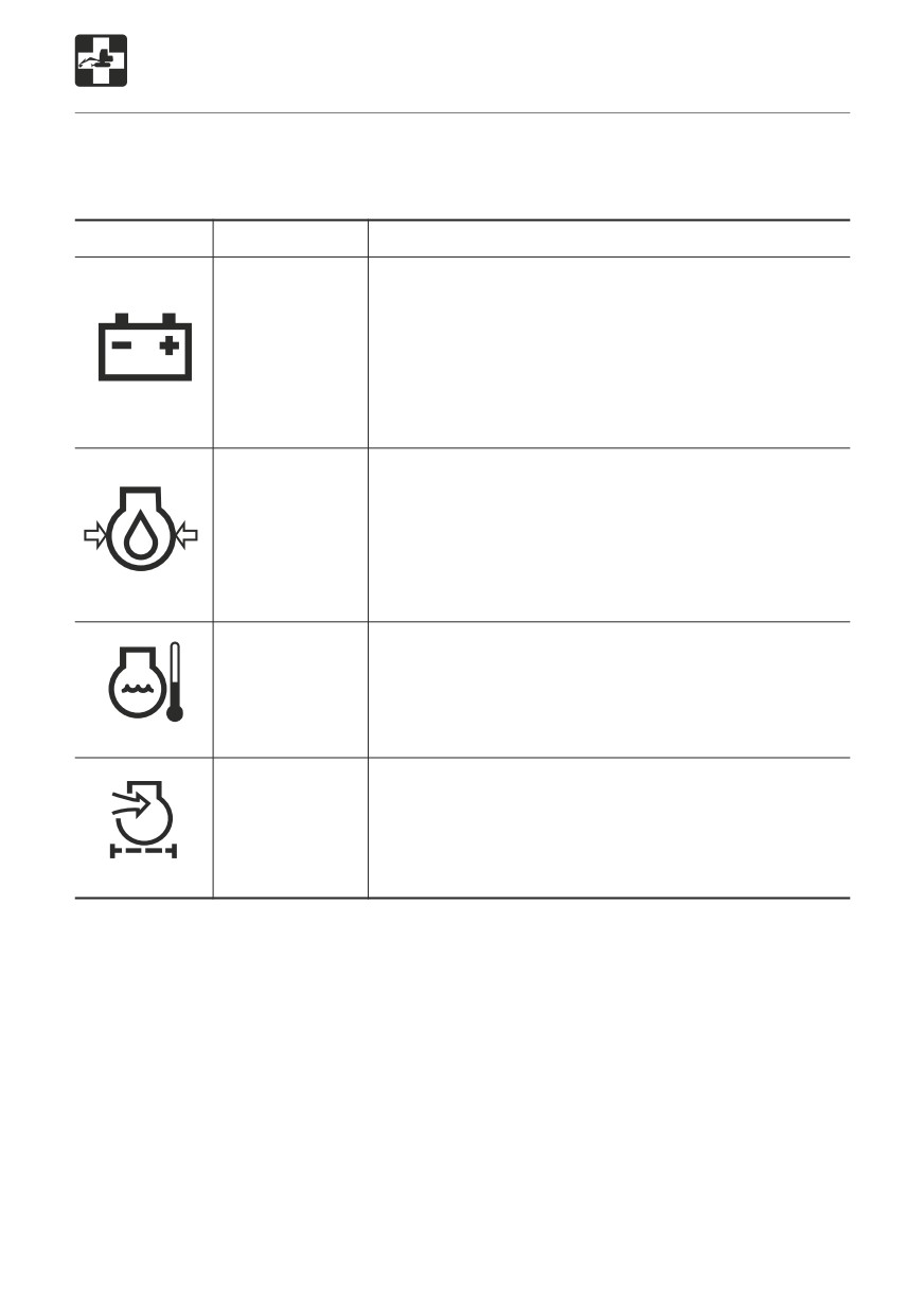
TROUBLESHOOTING
If a Warning Lamp Flashes
If an alarm is sounded or a warning lamp starts flashing during operation, park the machine in
a safe place and perform the procedures described below.
Warning lamp
Lamp name
Procedure
Battery charge
There is a problem with the fan belt or charger.
warning lamp
Inspect the fan belt for slack or breakage and adjust
as necessary. If the lamp continues flashing after
maintenance, there is a problem with the charger.
Consult a Takeuchi sales or service outlet.
OSOB080
Refer to page 125 “Inspecting and Adjusting the Fan
Belt”.
Engine oil
Inspect the engine oil level. If the lamp is flashing even
pressure
though the level is normal or if it continues flashing after
warning lamp
oil are added, consult a Takeuchi sales or service outlet.
Refer to page 117 “Inspecting and Replenishing the
Engine Oil”.
OS0B070
Coolant
The coolant temperature has risen irregularly and the
temperature
engine is overheating.
warning lamp
Refer to page 155 “If the Engine Overheats”.
C4BC12
Air cleaner
The air cleaner filter is clogged.
warning lamp
Refer to page 131 “Cleaning the Air Cleaner”.
G4B010
160