Takeuchi Hydraulic Excavator TB153FR (No.15820004~), TB180FR (17830004~). Operator's Manual - page 5
MAINTENANCE
Long-term Storage
Procedures for storage
During storage
If the machine is to be stored for 30 days or
more, store it indoors. If it must be stored
WARNING
outdoors, stop it on wood laid out on a flat
¡Do not operate the engine in an
surface and place a waterproof cover over it
enclosed area without adequate
so that it stays dry.
ventilation.
1. Clean the machine.
¡If natural ventilation is poor, install
2. Inspect for oil leakage, water leakage and
ventilators, fans, exhaust extension
loose nuts and bolts.
pipes or other artificial venting devices.
3. Add fuel and replace the hydraulic oil and
oil.
1. To prevent rusting, operate the machine
4. To prevent rusting and freezing, replace
once a month so that the oil is fully
the engine coolant with long-life coolant
circulated.
(LLC).
2. Inspect the battery and recharge it if
Refer to page 138 “Cleaning the Engine
necessary.
Cooling System”.
Have the battery charged by a Takeuchi
5. Use the grease gun to supply grease to
sales or service outlet.
the grease nipples.
6. Fully contract the bucket and arm cylinders
Starting the machine after storage
and ground the bucket and dozer blade.
7. Apply rust-prevention oil to the hydraulic
IMPORTANT: If the “Procedures for
cylinder rods.
storage” have not been performed and
8. Disconnect the cable from the battery’s “-”
the machine has been stored for a long
terminal and cover the battery to prevent
period of time, consult a Takeuchi sales
freezing.
or service outlet before reusing the
machine.
1. Wipe off the rust-prevention oil that was
applied to the hydraulic oil cylinders’ piston
rods.
2. Add fuel, oil and grease to all parts.
160
TROUBLESHOOTING
Symptoms that are not Malfunctions
162
If the Engine Overheats
163
If the Battery Goes Dead
164
If a Fuse Blows
166
After the Fuel Runs Out
168
If a Warning Lamp Flashes
169
Other Symptoms
170
To Lower the Boom
172
Towing
174
161
TROUBLESHOOTING
Symptoms that are not Malfunctions
The following symptoms are not
¡Performance decreases when an
malfunctions:
attachment weighing more than a
standard arm or bucket is mounted.
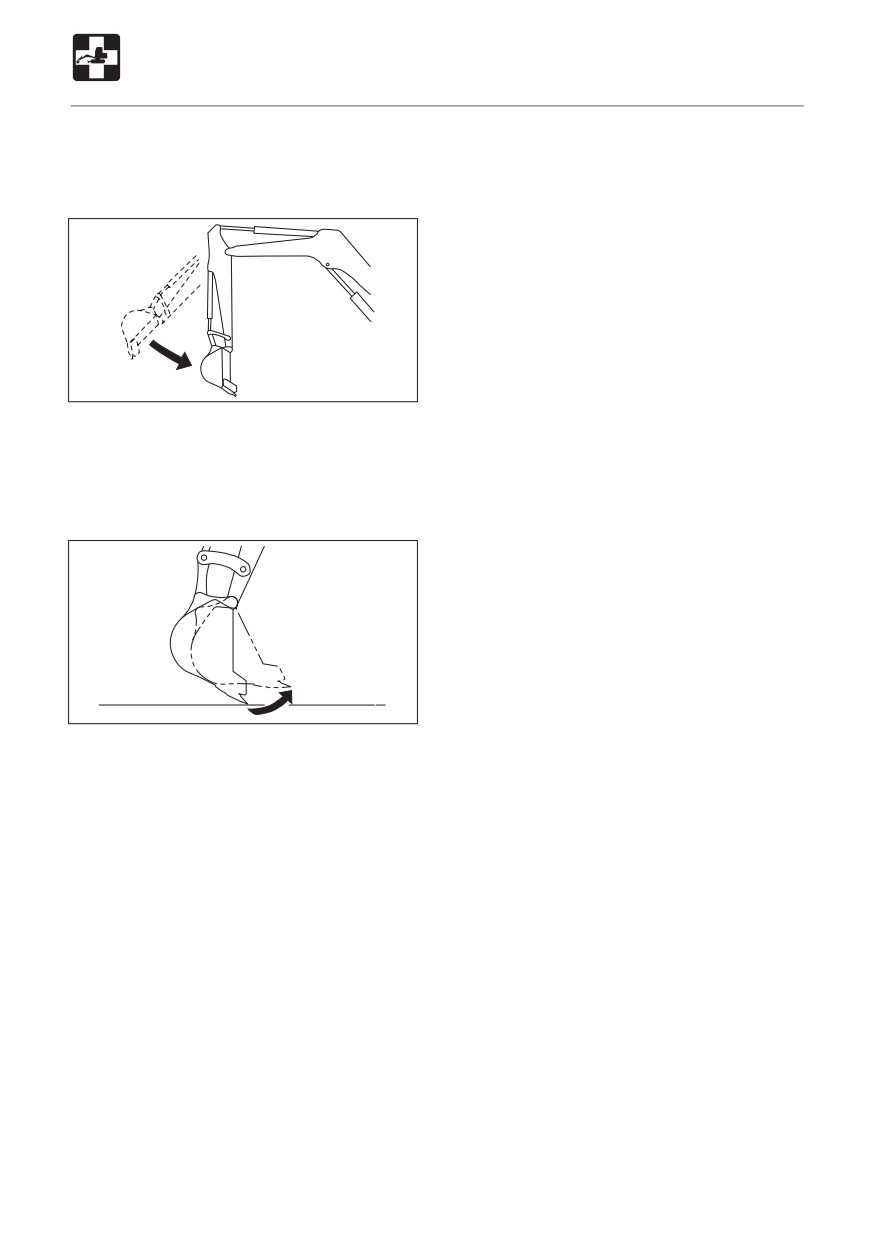
E4J001
¡ When the arm reaches the vertical position
while contracting it while the engine is
running at low speed, the contracting
speed slows down momentarily.
E4J002
¡When the bucket teeth reach the
horizontal position while the engine is
running at low speed, the speed of bucket
movement slows down momentarily.
¡ The slew motor produces noise at the
beginning and end of the slewing
operation.
¡ The travel motor produces noise when
stopped suddenly during high speed
travel.
¡The control valve produces noise if
excessive force is applied to the working
equipment and when the stroke end is
reached.
162
TROUBLESHOOTING
If the Engine Overheats
Procedure
WARNING
1. Park the machine in a safe place.
2. Inspect whether the engine oil pressure/
¡ Do not open the engine hood when
coolant level warning lamp is flashing or if
there is steam coming from the engine
there is steam coming out when the
room. The steam or hot water may
engine hood is closed.
spurt out, resulting in burns.
3. If there is steam, stop the engine
¡ Do not remove the radiator cap or drain
immediately and contact a Takeuchi sales
plugs when the coolant is hot. Stop the
or service outlet for repairs.
engine, let the engine and radiator cool
If the engine oil pressure/coolant level
and loosen the radiator cap or drain
warning lamp is off, run the engine at low
plugs slowly.
idle and let the water temperature
¡ Stop the engine and allow the machine
decrease.
to cool down before performing
4. Once the water temperature gauge drops
inspection and maintenance.
to the green zone, stop the engine.
5. Once the engine is cool, perform the
The following symptoms indicate
following inspections and procedures:
overheating :
• Fan belt slack
Adjust.
Refer to page 127.
• Coolant level
Add.
Refer to page 120.
• Water leakage
Repair.
• Radiator fins
Clean.
Refer to page 136.
• Sediment in cooling system
Clean.
Refer to page 138.
If the problem persists after the above
procedures are taken, contact a Takeuchi
¡An alarm is sounded and the coolant
sales or service outlet for repairs.
temperature warning lamp, engine
emergency lamp flashes.
When the engine oil pressure / coolant
level warning lamp is flashing
simultaneously, the coolant level is low.
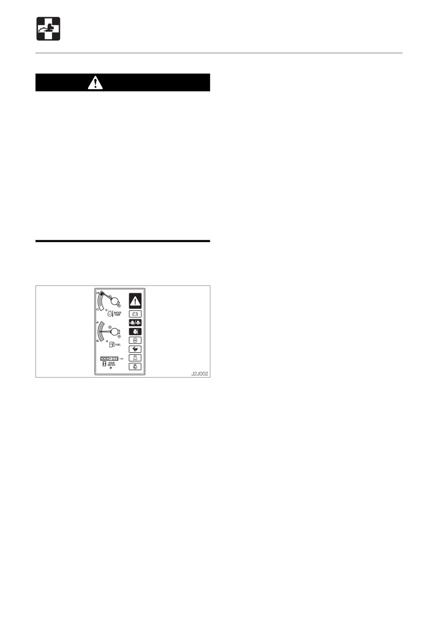
¡ The water temperature gauge is in the red
zone.
¡The engine slows down and the force
decreases.
¡ Steam comes from the engine room.
163
TROUBLESHOOTING
If the Battery Goes Dead
The following symptoms indicate that the
Connecting the jumper cables
battery is dead :
¡ The starter motor does not turn or turns
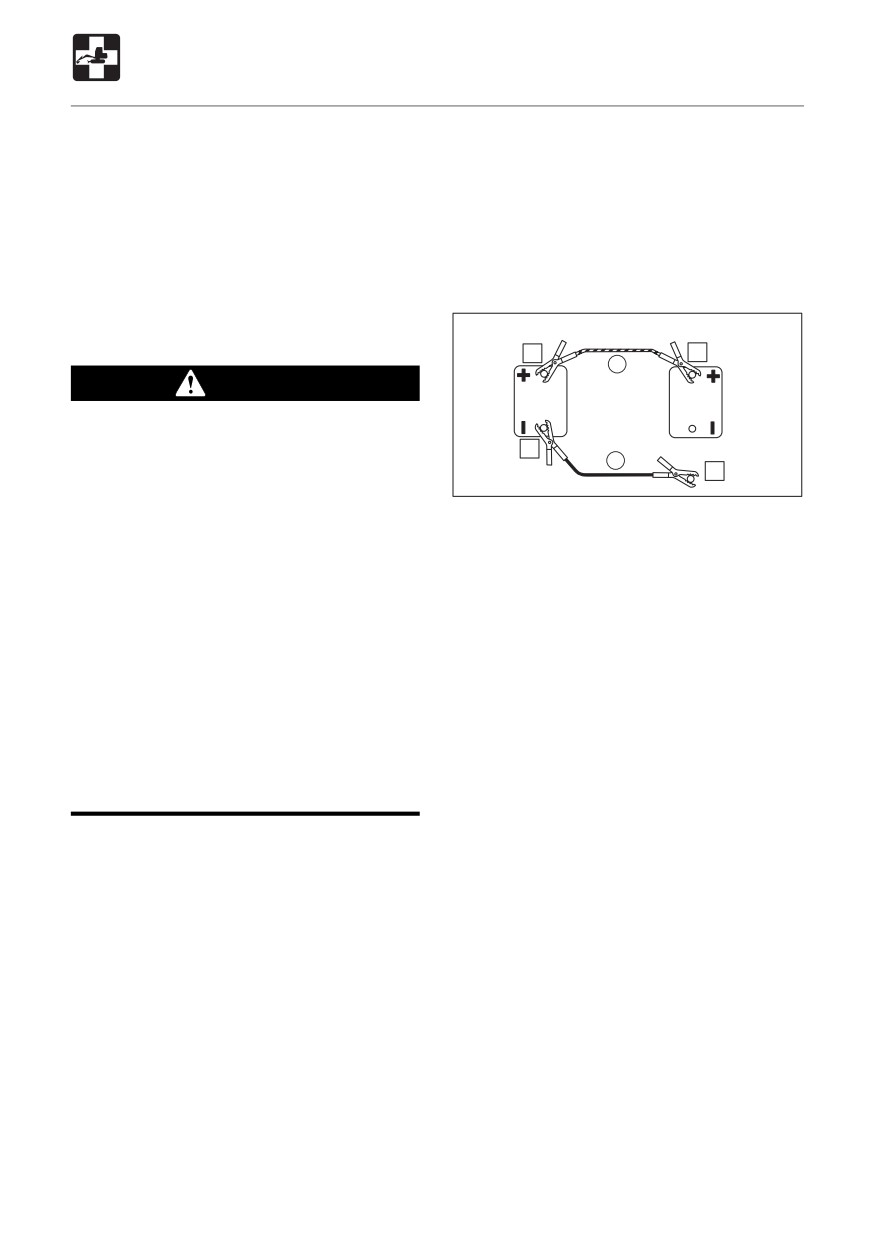
IMPORTANT: Set the starter keys of both
weakly, and the engine does not start.
the rescue vehicle and problem vehicle
¡ The horn is weak.
to the OFF position.
Refer to page 41 “Rear Cover”.
Procedure
Use jumper cables and start the engine using
Rescue vehicle battery Problem vehicle battery
the rescue vehicle’s battery.
2
1
R
WARNING
¡Use jumper cables only in the
recommended manner. Improper use
3
To engine block
B
of jumper cables can result in battery
4
E4J005
explosion or unexpected machine
motion.
1. Connect the clip of jumper cable (R) to
• Do not let the problem vehicle and
the problem vehicle’s “+” terminal.
rescue vehicle touch each other.
2. Connect the other clip of jumper cable (R)
• Do not let the “+” and “-” clips of the
to the rescue vehicle’s “+” terminal.
jumper cables touch each other.
3. Connect the clip of jumper cable (B) to
• Connect the jumper cables to the “+”
the rescue vehicle’s “-” terminal.
terminals first, and disconnect them
4. Connect the other clip of jumper cable (B)
from the “-” terminals (ground) first.
to the problem vehicle’s engine block.
• Connect the final clip of the jumper
Connect the clip as far from the battery as
cable to a point as far away from the
possible.
battery as possible.
¡ Use safety glasses when using jumper
Starting the engine
cables to start the machine.
1. Check that the clips are securely
connected to the terminals.
IMPORTANT: Use jumper cables and
2. Start the rescue vehicle’s engine and run
clips of a size suited to the battery’s
it at high speed.
capacity. Do not used damaged or
3. Start the problem vehicle’s engine.
corroded jumper cables and clips.
IMPORTANT: The rescue vehicle’s
battery must have the same capacity as
the problem vehicle’s battery.
IMPORTANT: Connect the clips securely.
164
TROUBLESHOOTING
If the Battery Goes Dead
Disconnecting the jumper cables
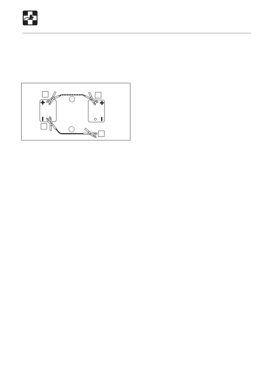
Once the engine starts, disconnect the
jumper cables following the connection
procedure in reverse order.
Rescue vehicle battery Problem vehicle battery
3
4
R
2
From engine block
B
1
E4J006
1. Disconnect the clip of jumper cable (B)
from the problem vehicle’s engine block.
2. Disconnect the other clip of jumper cable
(B) from the rescue vehicle’s “-” terminal.
3. Disconnect the clip of jumper cable (R)
from the rescue vehicle’s “+” terminal.
4. Disconnect the other clip of jumper cable
(R) from the problem vehicle’s “+” terminal.
Recharging
Have a Takeuchi sales or service outlet
recharge batteries that have gone dead.
165
TROUBLESHOOTING
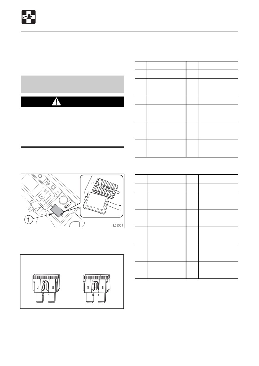
If a Fuse Blows
If a light does not turn on or the electric
Fuse Layout and Circuits Protected
system does not operate, a fuse may be
< TB153FR >
blown. Inspect the fuses.
Capacity Protected circuit
Capacity
Protected circuit
20A
Horn
Inspecting and Replacing the
10A
Radio,
10A
Controller
Fuse
Interior light
10A
Lever lock
30A
Stop solenoid
WARNING
30A
Lights
5A
Controller (ACC),
If the fuse blows as soon as it is replaced,
Accessory relay
there is a problem with the electric
system. Continued use may lead to fire.
30A
Wiper,
5A
Instrument cluster
Consult a Takeuchi sales or service
Cigarette lighter
Feed pump
outlet.
10A
Optional
5A
Interference
prevention
1. Turn the starter key to the OFF position
and stop the engine.
< TB180FR >
Capacity
Protected circuit
Capacity
Protected circuit
20A
Horn
10A
Radio,
10A
Throttle controller
Interior light
10A
Lever lock
30A
Emergency stop
relay
5A
Lights
5A
Controller (ACC),
2. Open the fuse box cover (1).
Accessory relay
3. Inspect for any blown fuses.
30A
Wiper,
5A
Instrument cluster
Cigarette lighter
Blown
Normal
10A
Optional
5A
Interference
prevention
E4J007
4. If a fuse is blown, replace it with a spare
fuse of the same capacity.
166
TROUBLESHOOTING
If a Fuse Blows
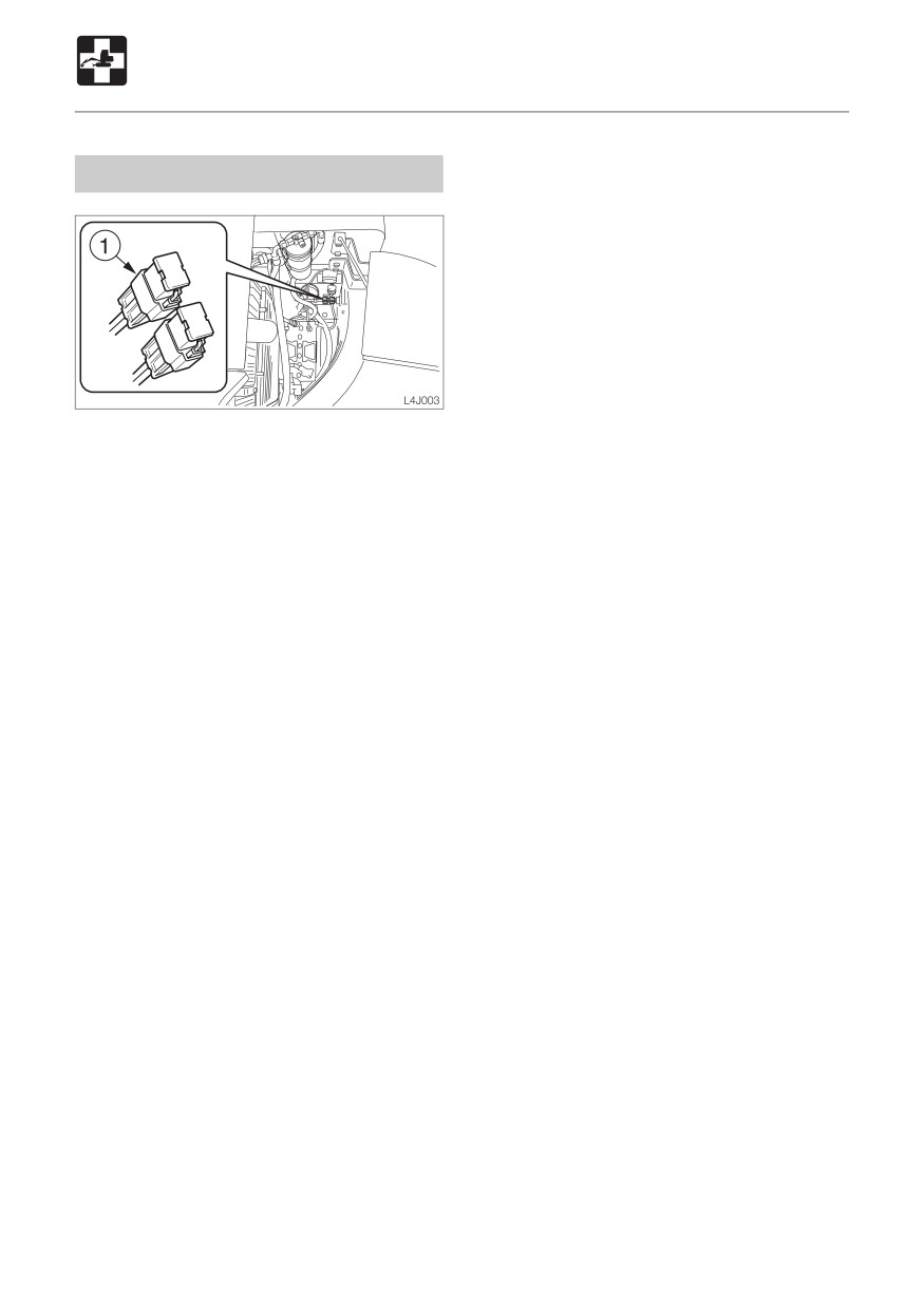
Inspecting the Fusible Link
If the power is not switched on after turning
the starter switch to the ON position, the
cartridge type fusible links (1) might be blown
open. Open the cover located at below of
the left operating lever and inspect. If the
fusible link is blown, please contact your
dealer.
Supplement: A fusible link is a large piece
of fuse wiring which is mounted in a circuit
which carries a large electrical current. Link
a regular fuse, the fusible link protects the
electrical parts and wiring from damage due
to abnormally large currents.
167
TROUBLESHOOTING
After the Fuel Runs Out
Bleeding the Air from the Fuel
System
1. Add fuel.
PREHEAT
OFF ON
START
E4D002
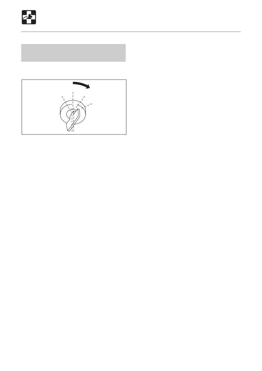
2. Turn the starter key to the ON position and
hold it there for about 20 seconds.
The automatic air bleeder bleeds the air
from the fuel system.
Supplement: Air in the fuel system can
make it difficult to start the engine and cause
engine problems. Also bleed the air when
the fuel tank is emptied or air in the fuel
system.
168
TROUBLESHOOTING
If a Warning Lamp Flashes
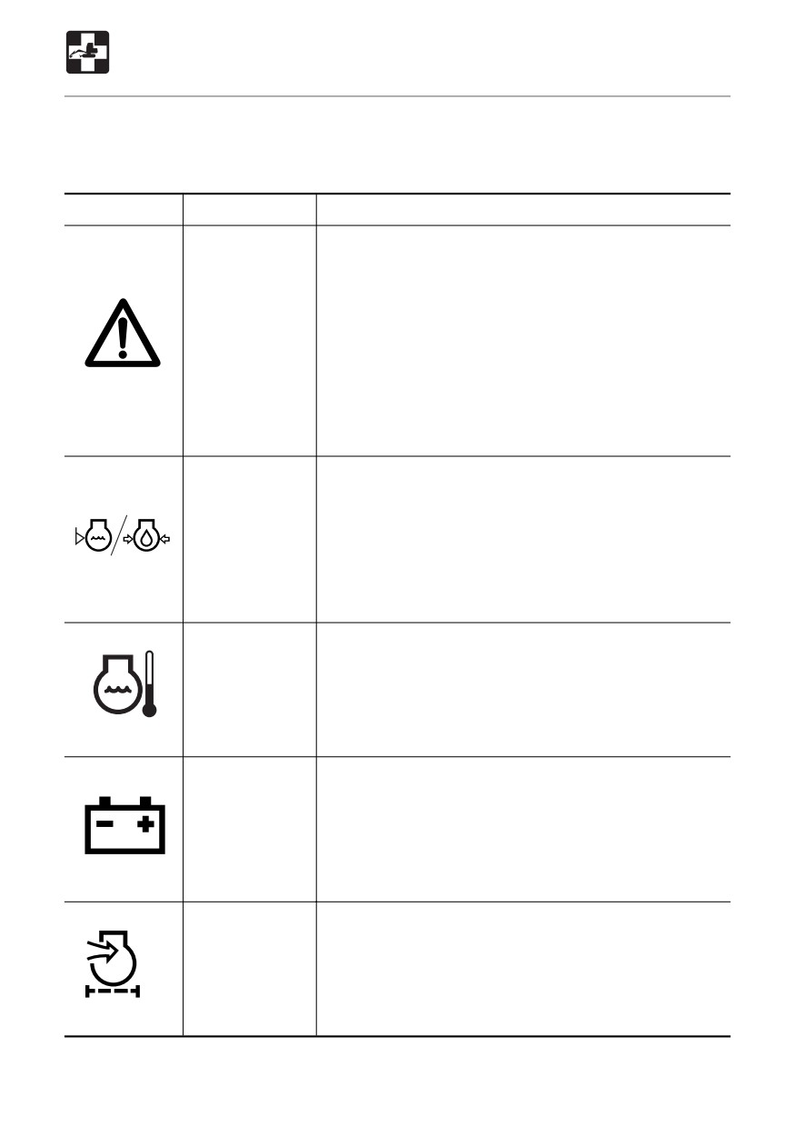
If an alarm is sounded or a warning lamp starts flashing during operation, park the machine
in a safe place and perform the procedures described below.
Warning lamp
Lamp name
Procedure
Engine
A problem has occurred in the engine lubrication system
emergency
or cooling system.
lamp
¡ When there is a problem in the engine lubrication
system or coolant level, the engine oil pressure /
coolant level warning lamp flashes simultaneously.
¡When the coolant water temperature has risen
irregularly, the coolant temperature warning lamp
G4B009
flashes simultaneously.
For the procedures, refer to the respective warning lamps
below.
Engine oil
Inspect the engine oil level or coolant level. If the lamp
pressure/
is flashing even though the level is normal or if it
coolant level
continues flashing after oil or coolant are supplied,
warning lamp
consult a Takeuchi sales or service outlet.
Refer to page 120 or 121 “Inspecting and replenishing
the coolant” or “Inspecting and Replenishing the
Engine Oil”.
Coolant
The coolant temperature has risen irregularly and the
temperature
engine is overheating.
warning lamp
Refer to page 163 “If the Engine Overheats”.
C
C4B012
Battery charge
There is a problem with the fan belt or charger. Inspect
warning lamp
the fan belt for slack or breakage and adjust as necessary.
If the lamp continues flashing after maintenance, there
is a problem with the charger. Consult a Takeuchi sales
or service outlet.
OSOB080
Refer to page 127 “Inspecting and Adjusting the Fan Belt”.
Air cleaner
The air cleaner filter is clogged.
warning lamp
Refer to page 134 “Cleaning the Air Cleaner”.
G4B010
169
TROUBLESHOOTING
Other Symptoms
For symptoms not included on the table below or if the problem persists after the proper
procedures have been taken, consult a Takeuchi sales or service outlet.
Symptom
Main cause
Procedure
Left and right operating
¡ Insufficient grease on left
¡ Add grease.
levers do not move
and right operating levers
Refer to page 146.
smoothly
Travel levers, offset
¡ Insufficient grease on travel
¡ Add grease.
pedal or blade lever do
levers, offset pedal or blade
Refer to page 146.
not move smoothly
lever
¡ Stretched wire < TB153FR >
¡ Adjust or replace. (Request
(Blade lever)
at a sales or service outlet)
Working equipment,
¡ Safety lock lever is raised
¡ Lower the safety lock lever.
auxiliary hydraulics,
Refer to page 53.
slewing or traveling
¡ Fuse is blown
¡ Replace the fuse.
operation not possible
Refer to page 166.
Digging force is
¡ Insufficient hydraulic oil level
¡ Replenish to the prescribed
insufficient
level.
Refer to page 122.
¡ Hydraulic oil is not heated
¡ Perform the warm-up
procedure.
Refer to page 76.
¡ Air cleaner is clogged
¡ Clean the air cleaner.
Refer to page 134.
¡ Hydraulic oil is not of
¡ Replace the hydraulic oil.
suitable type
Refer to page 142.
Traveling is not possible
¡ Stones or foreign objects are
¡ Remove the foreign object.
or not smooth
stuck
Machine does not travel
¡ Stones or foreign objects are
¡ Remove the foreign object.
straight forward
stuck
¡ Faulty crawler tention
¡ Adjust the crawler to the
adjustment.
prescribed tention.
Refer to page 128.
Travel speed cannot be
¡ Fuse is blown
¡ Replace the fuse.
changed
Refer to page 166.
Slewing is not possible
¡ Insufficient grease on slew
¡ Add grease.
or not smooth
bearing
Refer to page 130.
Hydraulic oil
¡ Insufficient hydraulic oil
¡ Replenish to the prescribed
temperature is too high
level.
Refer to page 122.
170
TROUBLESHOOTING
Other Symptoms
Symptom
Main cause
Procedure
Starter motor turns but
¡ Insufficient fuel
¡ Add fuel.
engine does not start
Refer to page 122.
¡ Air in fuel system
¡ Bleed the air.
Refer to page 168.
¡ Water in fuel system
¡ Drain the water.
Refer to page 132.
Crawlers slip off
¡ Crawlers are too loose
¡ Adjust the tension.
Refer to page 128.
¡ Tensioning cylinder valves
¡ Increase the tension.
are too loose < TB180FR >
Refer to page 158.
Engine exhaust is white
¡ Excessive engine oil
¡ Adjust to the prescribed
or bluish
level.
Refer to page 121.
¡ Insufficient fuel
¡ Replace the fuel.
Engine exhaust is
¡ Air cleaner is clogged
¡ Clean the air cleaner.
occasionally black
Refer to page 134.
Irregular noise is
¡ Low quality fuel is being
¡ Replace the fuel.
produced from the
used
¡ If the Engine Overheats
engine (combustion or
¡ Engine is overheating
Refer to page 163.
mechanical noise)
¡ Replace the muffler.
¡ Damage in muffler
(Request at a sales or
service outlet.)
171
TROUBLESHOOTING
To Lower the Boom
If the hoe attachment must be lowered to
< TB180FR >
the ground while the engine is stopped, use
the following procedure to do so.
This operation is dangerous and requires
experience. Have it performed by a Takeuchi
sales or service outlet.
Procedure
WARNING
¡Do not approach in the area of the
ground where the hoe attachment is to
be lowered. You may be hit by dirt
falling out of the bucket or the hoe
attachment as it drops.
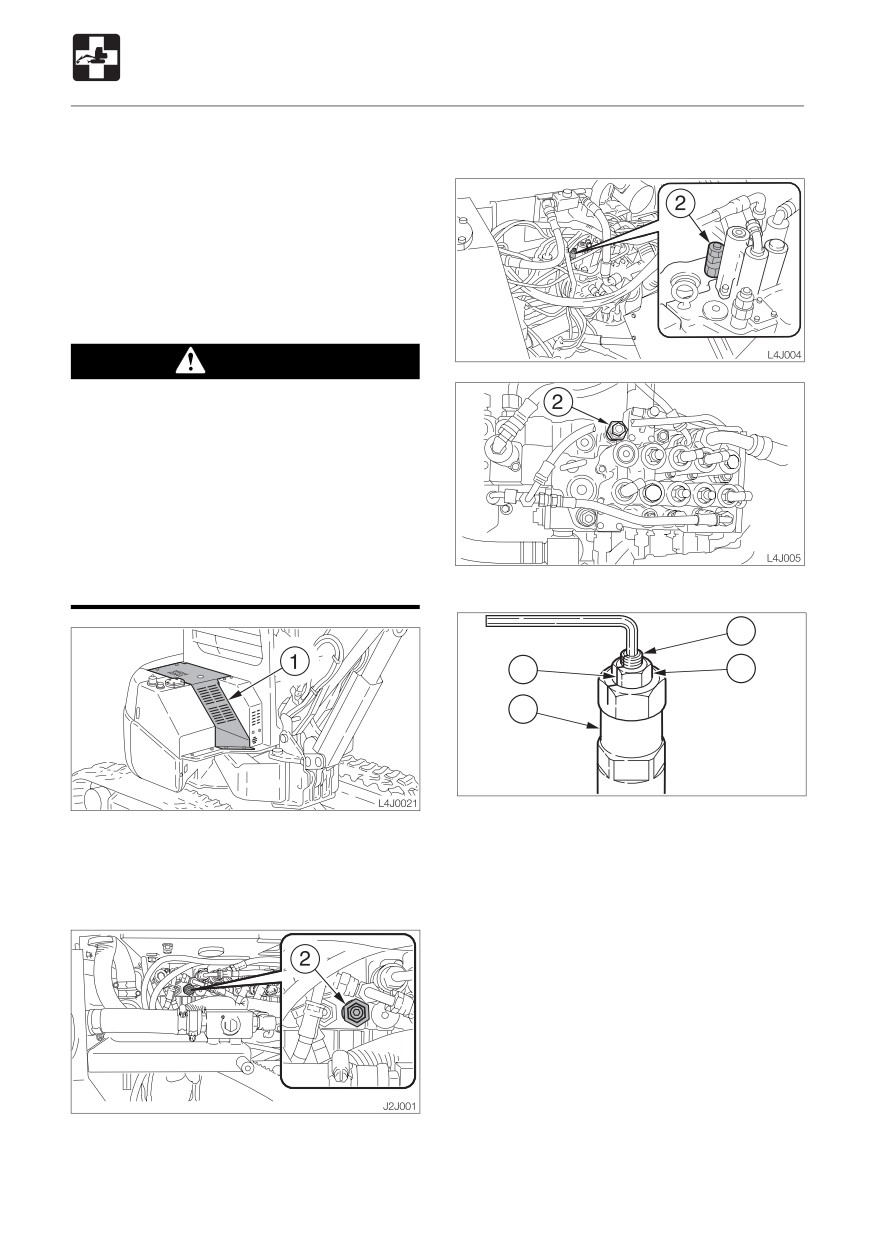
¡ Turn the port relief valve’s set screw
slowly so that the boom lowers slowly.
Do not turn the screw more than the
specified amount.
< TB153FR / TB180FR >
3
M
4
2
J1J004
2. Put mark (M) on the plug of the port relief
1. Loosen the bolts and remove the cover
valve (2) and set screw (3).
(1).
3. Gripping the set screw
(3) with a
hexagonal wrench so that it does not turn
< TB153FR >
together with the lock nut (4), loosen the
lock nut (4).
4. Turn the set screw (3) slowly 1 and 1/3
turns to lower the boom. < TB153FR >
Turn the set screw (3) slowly 1 turn to lower
the boom. < TB180FR >
5. Check for safety and machine stability.
6. Turn the set screw (3) back to its original
position.
172
TROUBLESHOOTING
To Lower the Boom
7. Gripping the set screw
(3) with a
hexagonal wrench so that it does not turn
together with the lock nut (4), tighten the
lock nut (4).
• Tightening torque : 27 to 31 N·m
(20 to 23 ft-lb.)
8. Reinstall the cover (1).
173
TROUBLESHOOTING
Towing
Using the light load towing hole
WARNING
IMPORTANT: Be sure to follow all the
When towing, selecting the wrong wire
steps below closely when using the light
rope, inspecting improperly, or towing in
load towing hole to tow. Failure to heed
the wrong way could lead to accidents
even one of the steps may cause damage
resulting in serious injury or death.
to the light load towing hole or other parts
¡The wire rope breaking or coming
of the frame.
detached could be extremely
dangerous. Use a wire rope suited for
the required towing force.
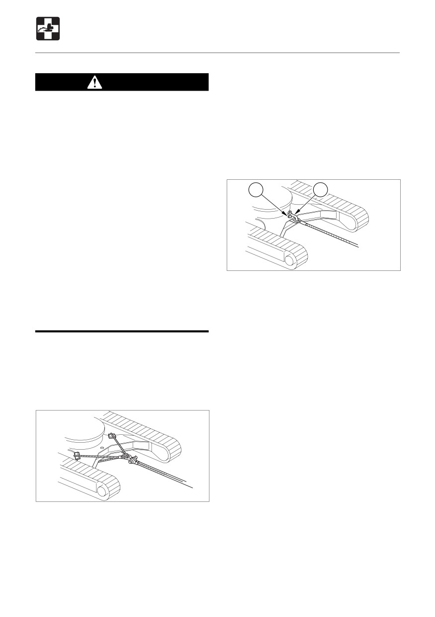
2
1
¡ Do not use a wire rope that is kinked,
twisted or otherwise damaged.
¡ Do not apply strong loads abruptly to
the wire rope.
¡ Use safety gloves when handling the
wire rope.
¡ Make sure there is an operator on the
N0J003
machine being towed as well as on the
¡ Maximum pulling force :
machine that is towing.
< TB153FR > 27500 N (6170 lb) or less
¡ Never tow on slopes.
< TB180FR > 43200 N (9700 lb) or less
¡ Do not let anyone near the wire rope
while towing.
1. Attach the wire rope to the shackle (1).
2. Fasten the shackle (1) to the light load
Towing the Machine
towing hole (2).
Use the procedure described below to tow
3. Attach the wire rope to the object to be
heavy objects or the machine itself if it should
towed.
get stuck in the mud and not be able to get
4. Make the wire rope horizontal and line up
out on its own.
straight with the travel frame.
5. Move the machine to tauten the wire rope.
6. Move the machine slowly and tow.
N0A006
1. Fasten the wire rope to the frame.
2. Place splints or other objects between the
wire rope and frame to prevent the
machine and wire rope from getting
damaged.
3. Move the machine to tauten the wire rope.
4. Move the machine slowly and tow.
174
SPECIFICATIONS
Main Specifications
176
Machine Dimensions
178
Operating Range
180
Lifting Capacities
183
175
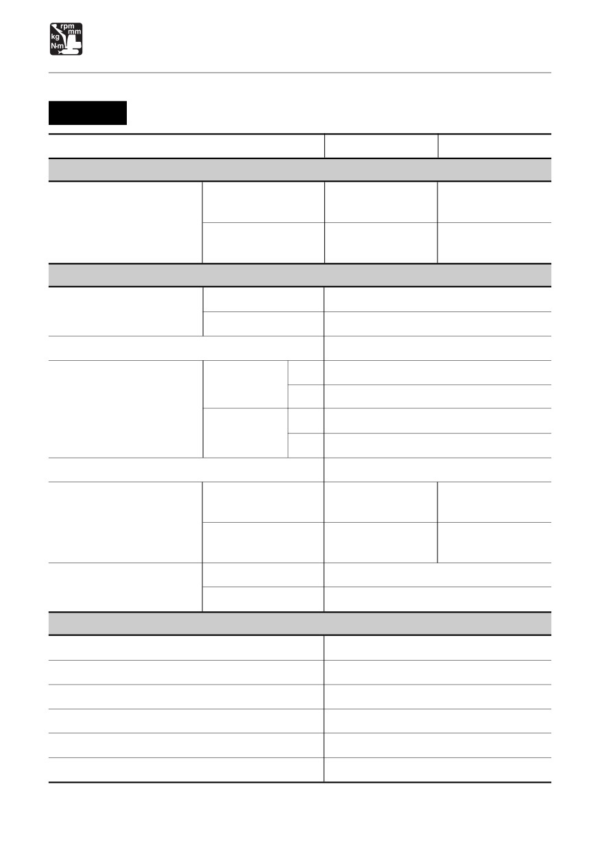
SPECIFICATIONS
Main Specifications
TB153FR
TYPE
CANOPY
CAB
MASS
5505 (12135)
5615 (12375)
Rubber crawlers
{5540 (12215)}
{5645 (12445)}
Machine mass kg (lb.)
(not including operator)
5575 (12285)
5680 (12525)
Steel crawlers
{5605 (12355)}
{5715 (12600)}
PERFORMANCE
Bucket capacity m3 (cu.ft.)
Heaped
0.141
(4.98)
(standard bucket)
Struck
0.102
(3.60)
Slew speed min-1 (rpm)
9.8
(9.8)
1st
2.8
(1.74)
Rubber
crawlers
2nd
5.0
(3.11)
Travel speed km/h (mph)
1st
2.5
(1.55)
Steel
crawlers
2nd
4.7
(2.92)
Gradeability (degrees)
30
31.6
(4.58)
32.2
(4.67)
Rubber crawlers
{31.8 (4.61)}
{32.4 (4.69)}
Ground pressure
kPa (psi)
32.0
(4.64)
32.6
(4.72)
Steel crawlers
{32.2 (4.67)}
{32.8 (4.75)}
Sound-power level
LWA 96
Noise level
dB(A)
Sound-pressure level
L
pA 76
ENGINE
Manufacturer and model
Yanmar 4TNV88-PTBZ1
Rated output
kW / min-1 (hp / rpm)
28.9 / 2400 (38.7 / 2400)
Displacement
mI (cu.in.)
2189 (133.6)
Starter
V - kW
12 - 2.3
Alternator
V - kW
12 - 0.48
Battery
V - Ah
12 - 72
{
} : Long Arm
176
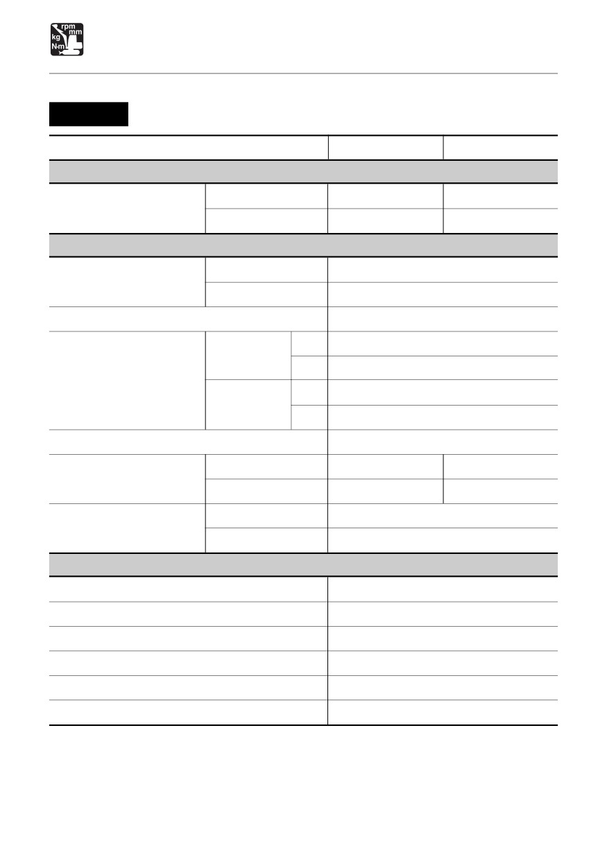
SPECIFICATIONS
Main Specifications
TB180FR
TYPE
Standard Arm
Long Arm
MASS
Rubber crawlers
8325 (18355)
8350 (18410)
Machine mass kg (lb.)
(not including operator)
Steel crawlers
8530 (18810)
8555 (18865)
PERFORMANCE
Bucket capacity m3 (cu.ft.)
Heaped
0.245
(8.65)
(standard bucket)
Struck
0.165
(5.83)
Slew speed min-1 (rpm)
9.9
(9.9)
1st
2.7
(1.68)
Rubber
crawlers
2nd
5.4
(3.36)
Travel speed km/h (mph)
1st
2.5
(1.55)
Steel
crawlers
2nd
5.0
(3.11)
Gradeability (degrees)
30
Rubber crawlers
37.6
(5.45)
37.7
(5.46)
Ground pressure
kPa (psi)
Steel crawlers
38.5
(5.59)
38.6
(5.60)
Sound-power level
LWA 98
Noise level
dB(A)
Sound-pressure level
L
pA 76
ENGINE
Manufacturer and model
Yanmar 4TNV98-STB1
Rated output
kW / min-1 (hp / rpm)
45.1 / 2200 (60.6 / 2200)
Displacement
mI (cu.in.)
3319 (202.5)
Starter
V - kW
12 - 3.0
Alternator
V - kW
12 - 0.66
Battery
V - Ah
12 - 72
177
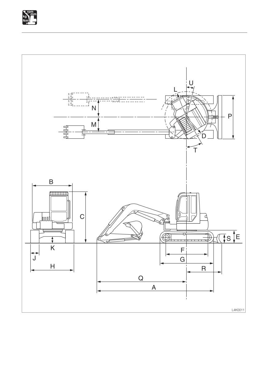
SPECIFICATIONS
Machine Dimensions
178
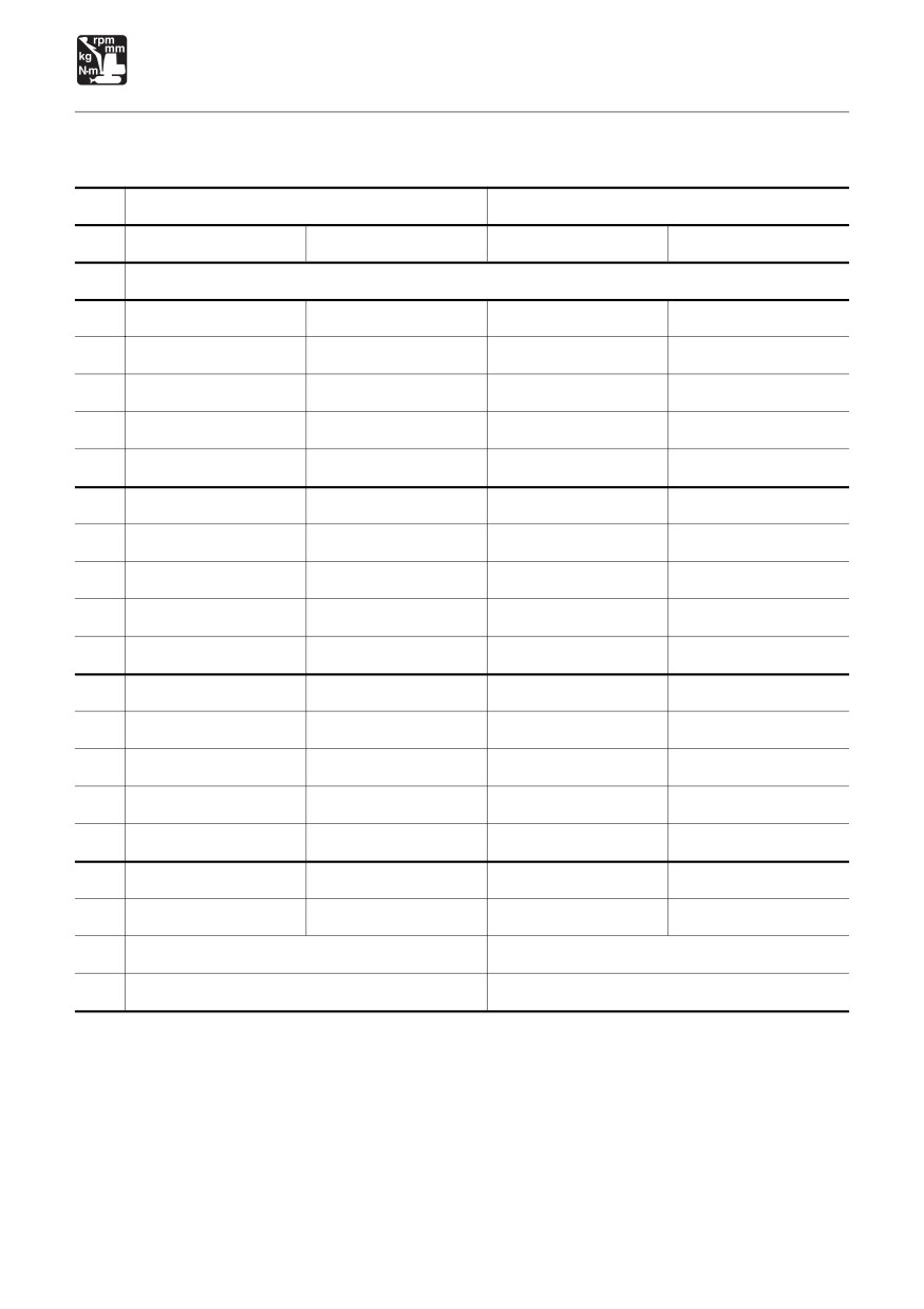
SPECIFICATIONS
Machine Dimensions
Units: mm (inches)
TB153FR
TB180FR
Standard Arm
Long Arm
Standard Arm
Long Arm
Rubber Crawlers
A
5330 (209.8)
5350 (210.6)
6150 (242)
6175 (243.1)
B
1860 (73.2)
←
2140 (84.3)
←
C
2570 (101.3) {2585 (101.7)}
←
2765 (108.9)
←
D
1110 (43.7)
←
1255 (49.4)
←
E
615 (24.2)
←
720 (28.3)
←
F
1985 (78.1)
←
2210 (87)
←
G
2500 (98.5)
←
2855 (112.4)
←
H
2000 (78.7)
←
2300 (90.6)
←
J
400 (15.7)
←
450 (17.7)
←
K
300 (11.8)
←
345 (13.5)
←
L
1285 (50.6)
←
1395 (55)
←
M
720 (28.3)
←
800 (31.4)
←
N
825 (32.4)
←
945 (37.2)
←
P
2000 (78.7)
←
2300 (90.6)
←
Q
4085 (160.8)
4105 (161.6)
4745 (186.8)
4775 (187.9)
R
1510 (59.4)
←
1855 (73.1)
←
S
430 (16.8)
←
500 (19.7)
←
T
30°
←
U
15°
←
{
} : Canopy
179
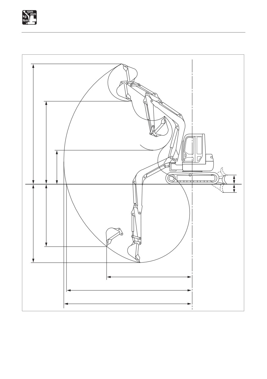
SPECIFICATIONS
Operating Range
E
F
G
J
K
D
C
H
B
A
J1K0021
180
SPECIFICATIONS
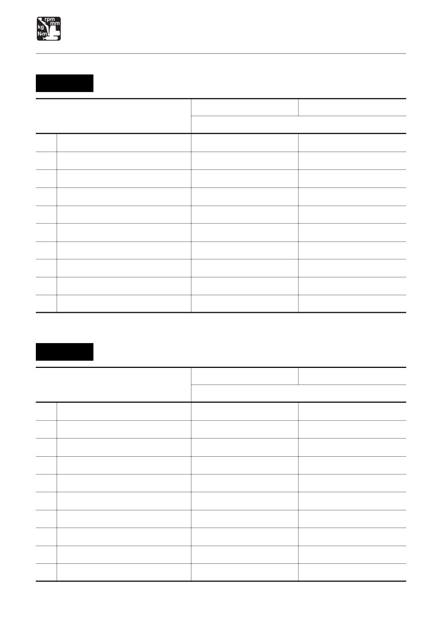
Operating Range
TB153FR
Units: mm (inches)
Standard Arm
Long Arm
Item
Rubber Crawlers
A
Max. digging radius
5905 (232.4)
6195 (243.9)
B
Max. ground digging radius
5765 (227.0)
6065 (238.7)
C
Max. digging depth
3590 (141.3)
3900 (153.5)
D
Max. vertical digging depth
2735 (107.7)
3030 (119.2)
E
Max. digging height
5320 (209.4)
5490 (216.2)
F
Max. dumping height
3710 (146.1)
3885 (152.9)
G
Min. dumping height
1435 (56.5)
1125 (44.3)
H
Max. vertical digging radius
3885 (153.0)
4075 (160.4)
J
Max. raising height
320 (12.6)
←
K
Max. lowering depth
325 (12.8)
←
TB180FR
Units: mm (inches)
Standard Arm
Long Arm
Item
Rubber Crawlers
A
Max. digging radius
6870 (270.5)
7195 (283.2)
B
Max. ground digging radius
6715 (264.3)
7045 (277.4)
C
Max. digging depth
4195 (165.2)
4545 (179.0)
D
Max. vertical digging depth
3165 (124.6)
3495 (137.6)
E
Max. digging height
6280 (247.2)
6460 (254.4)
F
Max. dumping height
4295 (169.1)
4475 (176.3)
G
Min. dumping height
1755 (69)
1405 (55.2)
H
Max. vertical digging radius
4700 (185.1)
4795 (188.8)
J
Max. raising height
505 (19.9)
←
K
Max. lowering depth
410 (16.1)
←
181
MEMO
182
SPECIFICATIONS
Lifting Capacities
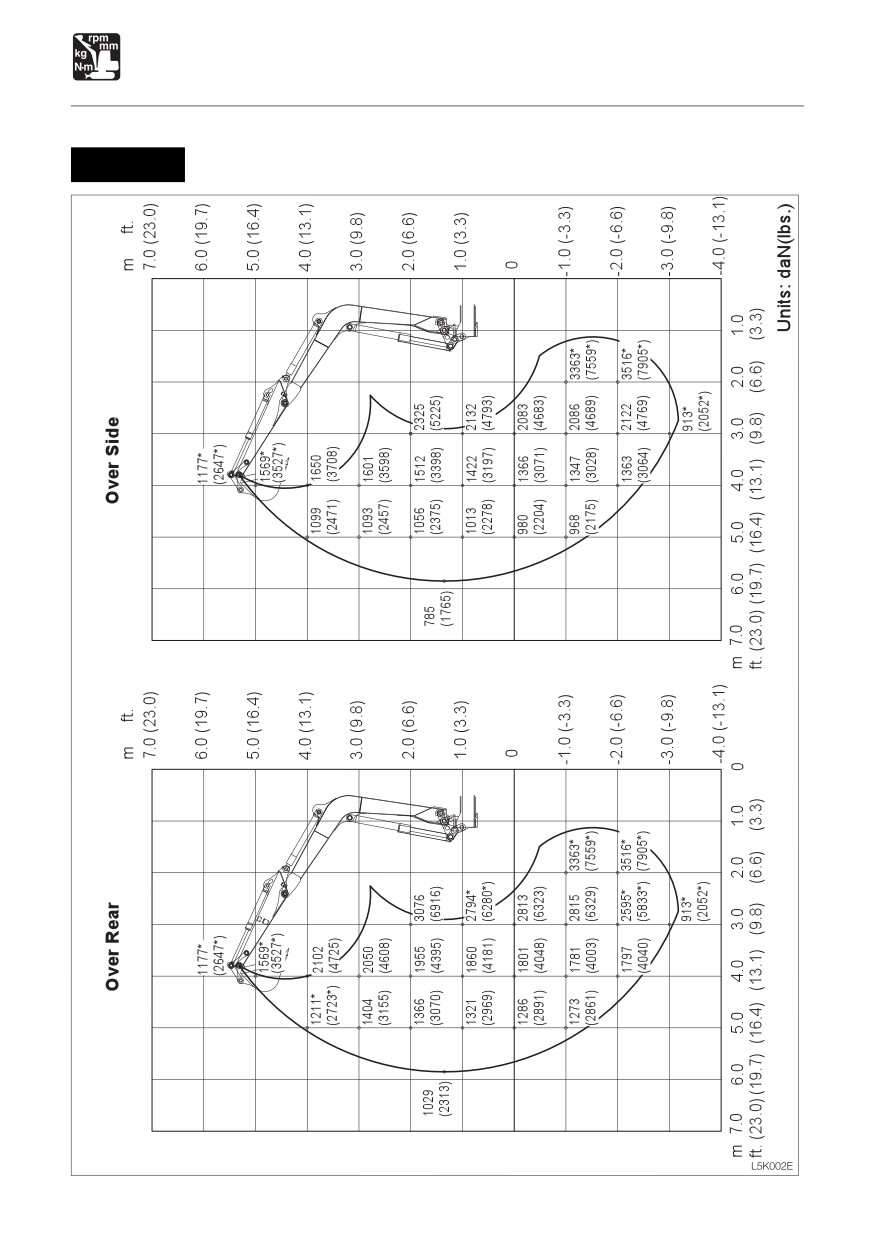
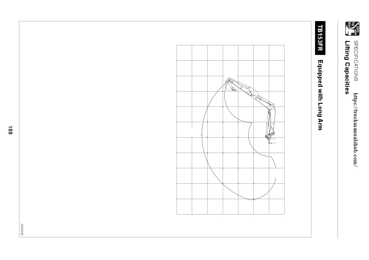
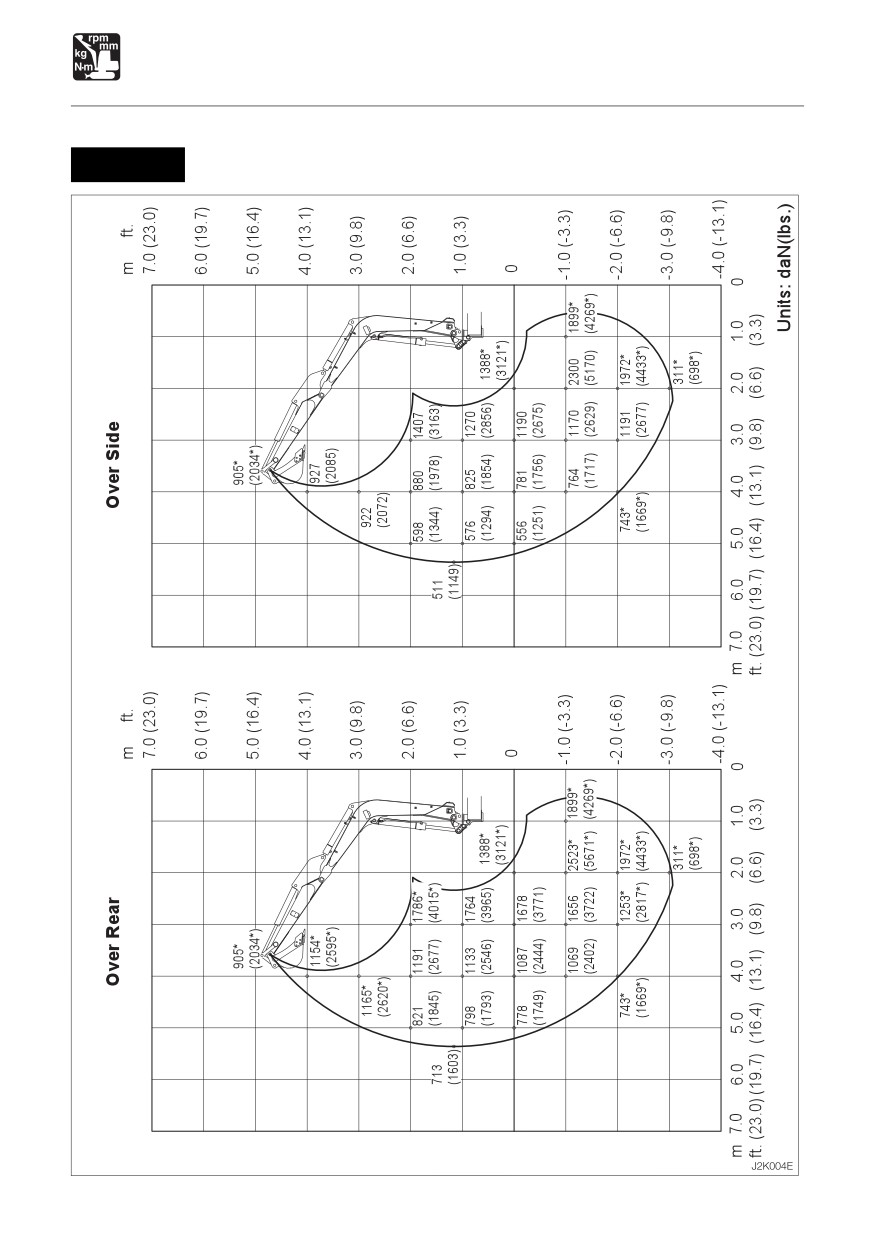
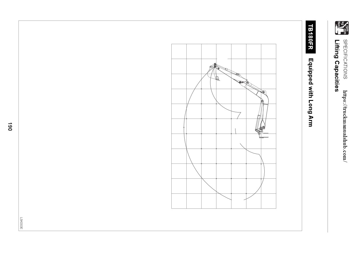
Rated lift capacity chart
¡ The loads in the charts do not exceed 87% of hydraulic lift capacity or 75% of tipping load.
¡ Rated lift capacities limited by rated hydraulic lift capacity are identified by an asterisk(*).
¡ The mass of slings and any auxiliary lifting devices shall be deducted from the rated load
to determine the net load that may be lifted.
¡ The load point is the bucket hinge pin, and the bucket posture is with the standard bucket
completely retracted under the arm.
¡ Units: daN (lbs.)
Load hooking system
A load hooking system with all of the following capacities must be provided and used.
1. A system which can withstand a weight of two times the rated lift capacity no matter at
what position the load is applied.
2. A system in which there is no risk of the lifted load falling from the hooking device, for
example one equipped with a hook slippage prevention device.
3. A system in which there is no risk of the hooking system slipping from the hoe attachment.
WARNING
¡ DO NOT attempt to lift or hold any load that is greater than these rated values at
their specified load radii and height.
¡ All rated lift capacities are based on the machine being level and on a firm supporting
surface. For safe working loads, the user is expected to make due allowance for the
particular job conditions such as soft or uneven ground, non-level condition, side
loads, hazardous conditions, experience of personnel, etc. The operator and other
personnel should fully acquaint themselves with the operator’s manual furnished
by the manufacturer before operating this machine, and rules for safe operation of
equipment shall be adhered to at all times.
183
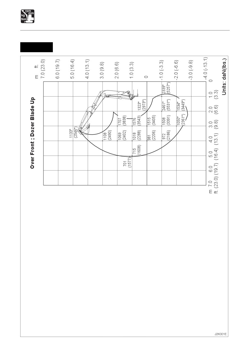
SPECIFICATIONS
Lifting Capacities
TB153FR Equipped with Standard Arm
184

SPECIFICATIONS
Lifting Capacities
TB153FR
Equipped with Standard Arm
185
Over Front ; Dozer Blade Up
m ft.
7.0
(23.0)
1177*
6.0
(19.7)
(2647*)
5.0
(16.4)
1569*
(3527*)
4.0
(13.1)
1211*
1899
(2723*)
(4269)
3.0
(9.8)
1249
1847
(2807)
(4151)
2.0
(6.6)
1210
1751
2779
900
(2721)
(3937)
(6248)
(2023)
1.0
(3.3)
1165
1656
2566
(2619)
(3722)
(5768)
0
1130
1596
2512
(2541)
(3587)
(5647)
-1.0 (-3.3)
1117
1575
2515
3363*
(2511)
(3541)
(5654)
(7559*)
-2.0 (-6.6)
1592
2554
3516*
(3579)
(5742)
(7905*)
-3.0 (-9.8)
913*
(2052*)
-4.0 (-13.1)
m 7.0
6.0
5.0
4.0
3.0
2.0
1.0
0
ft. (23.0)
(19.7)
(16.4)
(13.1)
(9.8)
(6.6)
(3.3)
Units: daN(lbs.)
SPECIFICATIONS
Lifting Capacities
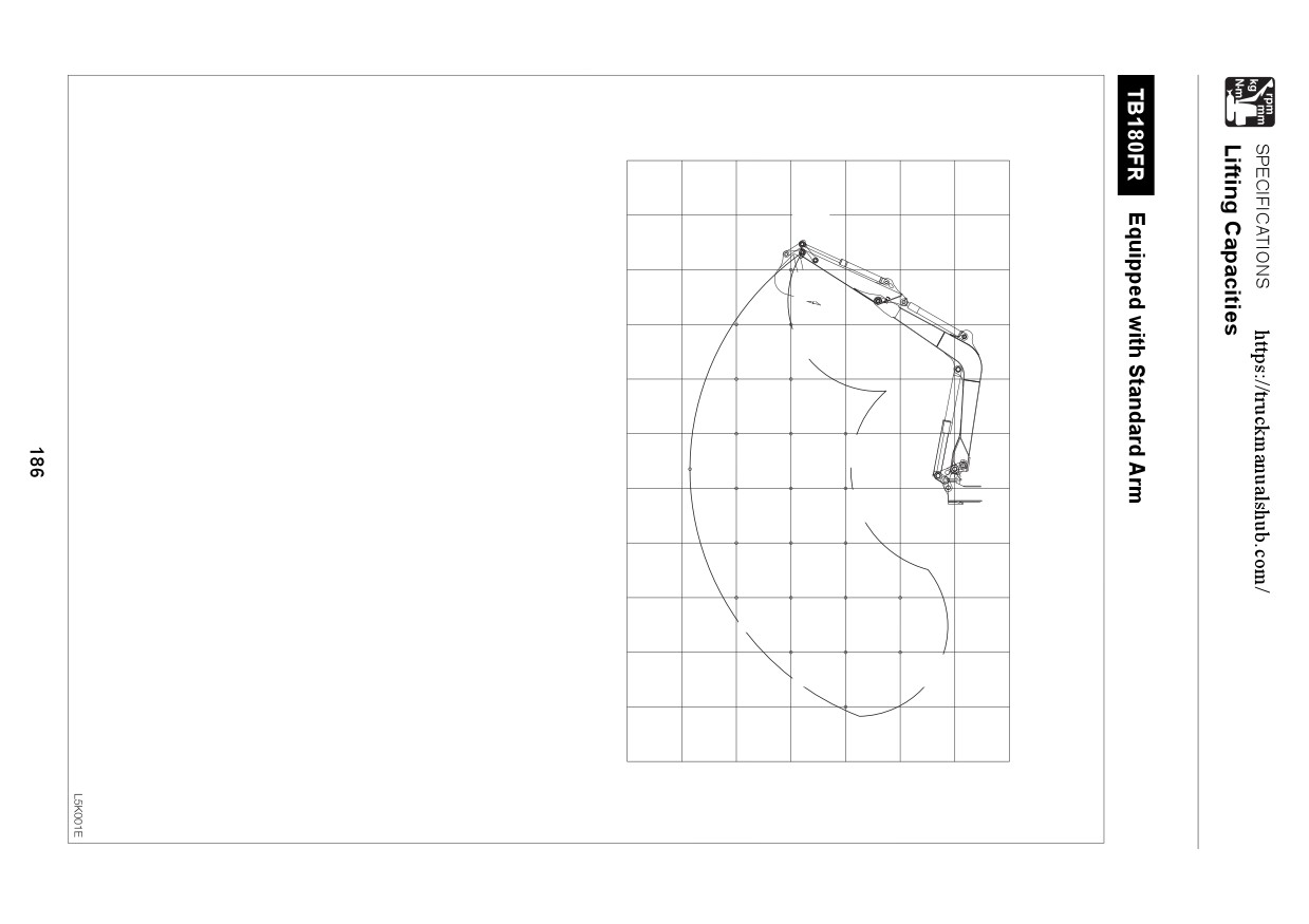
TB180FR Equipped with Standard Arm
187
Over Front ; Dozer Blade Up
m ft.
7.0
(23.0)
6.0
(19.7)
905*
(2034*)
5.0
(16.4)
4.0
(13.1)
1123
(2524)
3.0
(9.8)
1117
(2511)
2.0
(6.6)
732
1073
1735
632
(1646)
(2412)
(3901)
(1420)
1.0
(3.3)
709
1015
1589
(1594)
(2282)
(3571)
1388*
(3121*)
0
689
969
1502
(1549)
(2179)
(3377)
-1.0 (-3.3)
951
1480
2523*
1899*
(2137)
(3328)
(5671*)
(4269*)
-2.0 (-6.6)
743*
1253*
1972*
(1669*)
(2817*)
(4433*)
-3.0 (-9.8)
311*
(698*)
-4.0 (-13.1)
m 7.0
6.0
5.0
4.0
3.0
2.0
1.0
0
ft. (23.0)
(19.7)
(16.4)
(13.1)
(9.8)
(6.6)
(3.3)
Units: daN(lbs.)
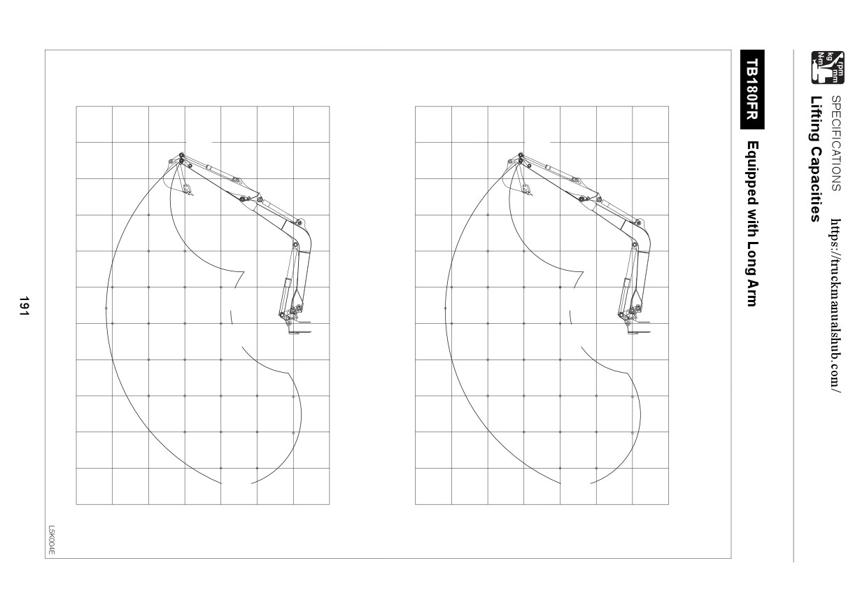
SPECIFICATIONS
Lifting Capacities
TB153FR
Equipped with Long Arm
189
Over Front ; Dozer Blade Up
m ft.
7.0
(23.0)
1051*
6.0
(19.7)
(2363*)
5.0
(16.4)
4.0
(13.1)
1296
(2914)
3.0
(9.8)
1278
(2873)
1887
(4243)
2.0
(6.6)
830
890
1234
1790
2882
(1866)
(2001)
(2774)
(4023)
(6480)
1.0
(3.3)
868
1183
1684
2636
(1951)
(2659)
(3787)
(5925)
0
1141
1610
2532
(2564)
(3620)
(5692)
-1.0 (-3.3)
1118
1577
2510
2909*
2580*
(2513)
(3545)
(5643)
(6540*)
(5800*)
-2.0 (-6.6)
1580
2532
4551*
3672*
(3551)
(5693)
(10231*)
(8255*)
-3.0 (-9.8)
1714*
(3853*)
2255*
(5069*)
-4.0 (-13.1)
m 7.0
6.0
5.0
4.0
3.0
2.0
1.0
0
ft. (23.0)
(19.7)
(16.4)
(13.1)
(9.8)
(6.6)
(3.3)
Units: daN(lbs.)
Over Rear
Over Side
m ft.
m ft.
7.0
(23.0)
7.0
(23.0)
1051*
1051*
6.0
(19.7)
6.0
(19.7)
(2363*)
(2363*)
5.0
(16.4)
5.0
(16.4)
4.0
(13.1)
4.0
(13.1)
1451
1138
(3261)
(2558)
3.0
(9.8)
3.0
(9.8)
1433
1120
(3220)
2090
(2519)
1639
(4698)
(3683)
2.0
(6.6)
2.0
(6.6)
949*
1015
1389
1993
3178
725
779
1079
1547
2417
(2133*)
(2282)
(3123)
(4481)
(7144)
(1630)
(1752)
(2425)
(3479)
(5434)
1.0
(3.3)
1.0
(3.3)
993
1338
1889
2934
758
1030
1449
2195
(2233)
(3008)
(4246)
(6597)
(1704)
(2316)
(3258)
(4934)
0
0
1296
1815
2832
990
1380
2101
(2914)
(4081)
(6367)
(2226)
(3102)
(4724)
-1.0 (-3.3)
-1.0 (-3.3)
1274
1782
2811
2909*
2580*
969
1349
2082
2909*
2580*
(2864)
(4006)
(6318)
(6540*)
(5800*)
(2177)
(3032)
(4679)
(6540*)
(5800*)
-2.0 (-6.6)
-2.0 (-6.6)
1785
2833
4551*
3672*
1351
2102
4280
3672*
(4012)
(6368)
(10231*)
(8255*)
(3038)
(4725)
(9621)
(8255*)
-3.0 (-9.8)
-3.0 (-9.8)
1714*
1714*
(3853*)
2255*
(3853*)
2255*
(5069*)
(5069*)
-4.0 (-13.1)
-4.0 (-13.1)
m 7.0
6.0
5.0
4.0
3.0
2.0
1.0
0
m 7.0
6.0
5.0
4.0
3.0
2.0
1.0
0
ft. (23.0) (19.7)
(16.4)
(13.1)
(9.8)
(6.6)
(3.3)
ft. (23.0)
(19.7)
(16.4)
(13.1)
(9.8)
(6.6)
(3.3)
Units: daN(lbs.)
192
OPTIONS
General Precautions
194
Safety Signs (Decals)
196
Switching the Lever Pattern
198
3-Hole Bucket < TB180FR >
199
Hydraulic Breaker
200
Load Safety Device
202
Accumulator
204
Pre Cleaner < TB180FR >
205
Second Auxiliary Hydraulics
206
Third Auxiliary Hydraulics
208
Fourth Auxiliary Hydraulics < TB180FR > .. 210
Travel Alarm
212
Fuel Supply Pump < TB180FR >
213
Air Conditioner
214
Immobilizer System
224
193
OPTIONS
General Precautions
Precautions on Safety
WARNING
Heed the following when removing or installing an attachment or option:
¡ Consult with a Takeuchi dealer before installing optional attachments.
¡ Do not use attachments that have not been approved by Takeuchi or a Takeuchi
dealer. Doing so may compromise safety or adversely affect the machine’s operation
or service life.
¡ Takeuchi will not be held responsible for any injuries, accidents or damage to
products caused by the use of a non-approved attachment.
¡ Choose a flat, hard surface to perform the operations. Also make sure there is enough
light and good ventilation.
¡ Clean the area, remove any articles that may get in the way or be dangerous, and
remove any spilt oil or grease.
¡ When performing lifting operations, determine a person to lead the operations and
always follow that person’s instructions.
• Follow the leader’s instructions on operating methods and procedures.
• Determine a signal leader and heed this person’s signals.
¡ When removing or installing the hoe attachment, place it in a stable position so that
it does not tip over.
¡ Due to the risk of loads falling and / or hitting people, do not allow unauthorized
personnel in the work area.
¡ Use the crane to carry heavy objects (25 kg (55 lb.) or greater).
¡ When removing heavy parts, be sure to prop them up before removing them. When
lifting them with a crane, be careful to balance them properly.
¡ Operating with loads suspended with the crane is dangerous. Place loads on a
stand and check for safety.
¡ When attaching the boom or arm, failure to follow proper procedures could result in
serious damage. Consult with a Takeuchi dealer beforehand.
Precautions on Installing Attachments
After replacing optional attachments or other special attachments, test-run them, then inspect
the hydraulic oil level and add oil if necessary.
In addition, consult with a Takeuchi dealer for details of removal and installation procedures.
194
OPTIONS
General Precautions
Precautions on Operating Attachments
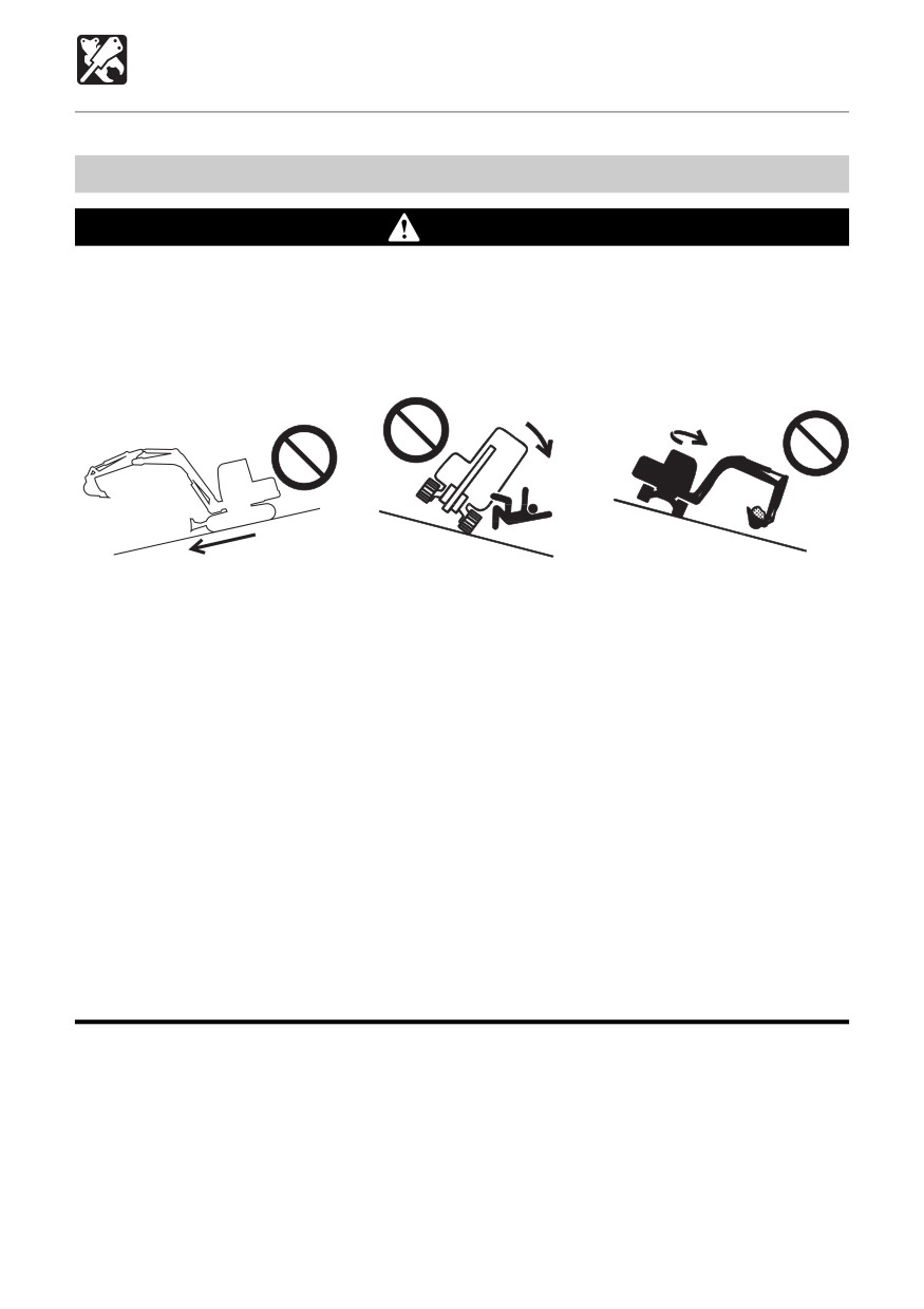
WARNING
Long attachments reduce machine stability. When traveling down steep slopes or
slewing on slopes, the machine may loose its balance and tip over.
The following operations are particularly dangerous. Do not perform them.
¡ Traveling down slopes
¡ Traveling across slopes
¡ Slewing on slopes
with the attachment lifted
OE3A2531
OE3A271
OE3A331
¡ When heavy attachments are installed, the overslew (the distance from where the
operation to stop slewing is performed until slewing stops completely) increases
and mistakes in judgment may result in the attachment hitting surrounding objects.
Allow for plenty of room between the attachment and obstacles.
In addition, the natural drop (the gradual dropping of the attachment under its own
weight when it is stopped in midair) also increases when heavy attachments are
installed.
¡ The machine can tip over more easily in the lateral direction than in the longitudinal
direction.
• Do not slew (swing) sideways with excessive weight at the front. In particular do
not slew sideways on slopes.
• The front is heavier for machines equipped with breakers, crushers than for
machines equipped with the standard bucket. Do not operate such machines
sideways, especially with the digging arm (boom) downhill.
¡ When a long arm or a telescopic arm is installed, the operating range suddenly
increases and mistakes in judgment may result in the attachment hitting surrounding
objects. Allow for plenty of room between the attachment and obstacles.
195
OPTIONS
Safety Signs (Decals)
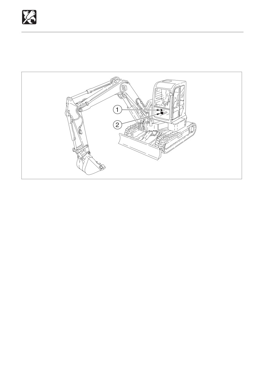
Keep all safety signs clean and legible.
Replace all missing, illegible or damaged safety and warning signs.
There are other safety signs in addition to the ones listed here. Treat them in the same way.
L4L012
196
OPTIONS
Safety Signs (Decals)
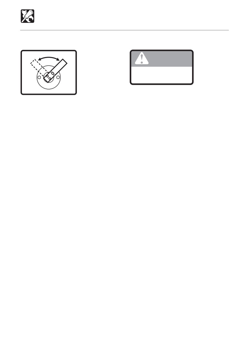
1. No.03593-32200
2. No.03593-32300
A
G
(ISO)
WARNING
Check what type of lever control
arrangement you are operating
with before beginning operations.
03593-32300
03593-32200
197

OPTIONS
Switching the Lever Pattern
The operating pattern of the left and right operating levers can be changed.
WARNING
Before starting the engine, check the selector to see which operating pattern the left
and right operating levers are set for.
A
ISO
G
JCB
C4L004
Switching the Lever Pattern
1. Park the machine in a safe place and turn
off the engine.
2. Fully open the cab door and fix it in place.
3. Remove the cover (1).
4. Loosen the wing bolt (2).
5. Turn the selector valve lever (3) and switch
the pattern.
6. Tighten the wing bolt (2) and fasten the
lever (3) in place.
(A) : ISO pattern
7. Close the cover (1).
(G) : JCB pattern
8. Check the lever pattern.
198
OPTIONS
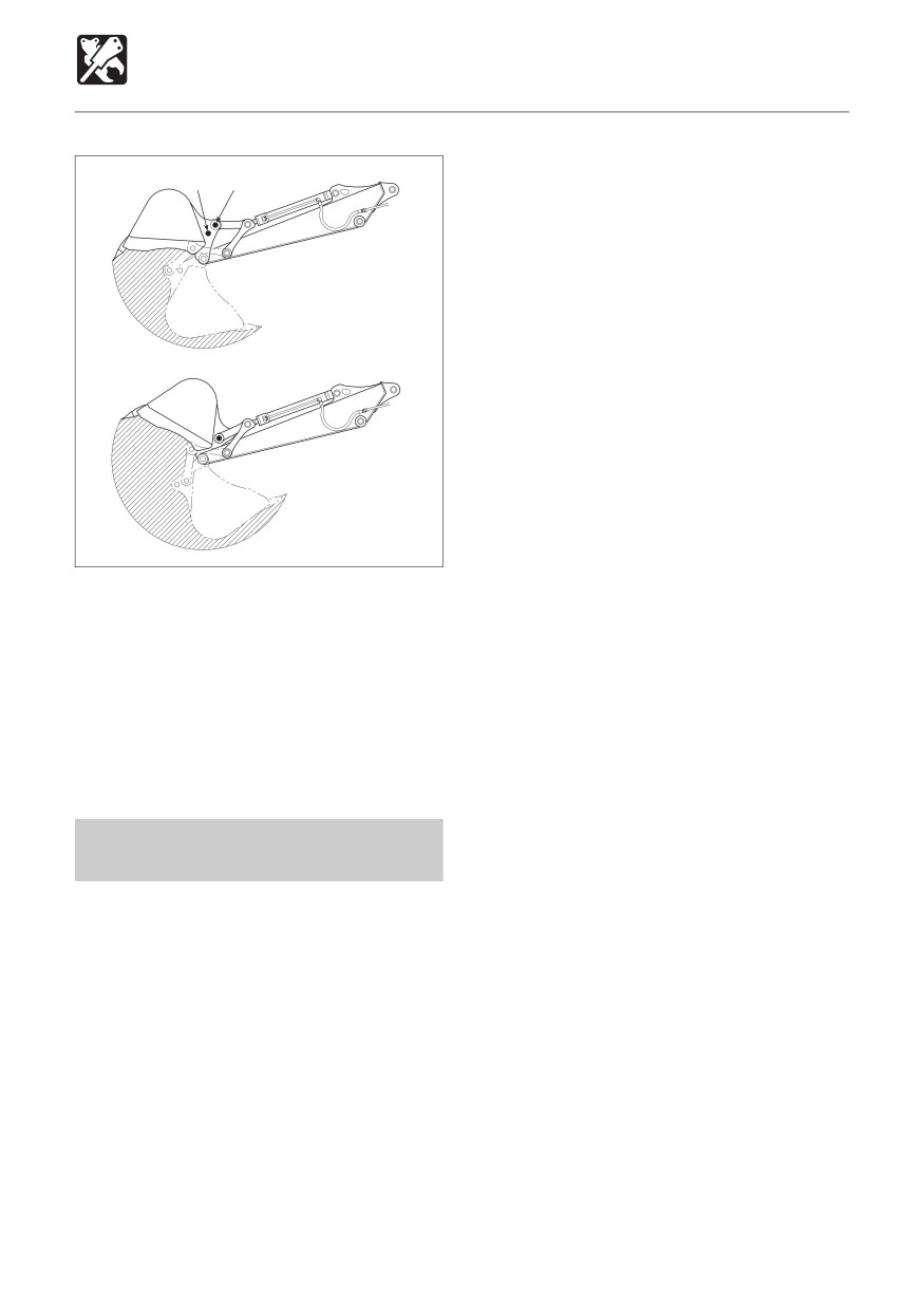
3-Hole Bucket < TB180FR >
A B
OL1L170
OL1L180
The digging capacity increases when the
bucket’s link arm installation position is
switched from (A) to (B). However, this
shortens the bucket stroke.
• Struck capacity (SAE) :
0.210 m3 (0.275 cu. yd.)
• Rated capacity (SAE) :
0.261 m3 (0.341 cu. yd.)
Changing the Link Arm
Installation Position
Refer to page 148 “Replacing the Bucket” in
the manual.
199