Takeuchi Hydraulic Excavator TB153FR (No.15820004~), TB180FR (17830004~). Operator's Manual - page 3
OPERATION
Machine Operation
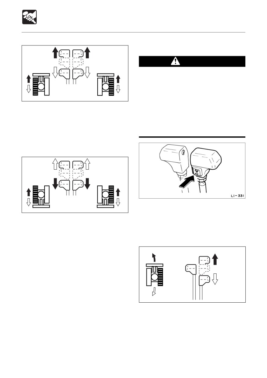
Traveling in 2nd (High) Speed
Neutral
Neutral
WARNING
When a load greater than a set value is
applied during 2nd speed (high speed)
travel, the speed will automatically slow
down by switching to 1st speed (low
E4D015
speed). Thereafter, when the load
When the dozer blade is in front of the
becomes lighter, the speed will increase
operator’s seat :
by returning to 2nd speed (high speed).
a To move forward :
Exercise due caution since the travel
Tilt the levers forward.
speed changes automatically.
e To move backward :
Tilt the levers backward.
Neutral
Neutral
Press the travel speed switch on the right
E4D016
travel lever to switch to 2nd (high) speed,
When the dozer blade is behind the
and press it again to return to 1st speed (low
operator’s seat :
speed).
a To move forward :
Tilt the levers backward.
Pivot Turn
e To move backward :
Tilt the levers forward.
Neutral
E4D017
Turning to the left when stopped :
a To turn forward to the left :
Tilt the right lever forward.
e To turn backward to the left :
Tilt the right lever backward.
To turn to the right, operate the left lever in
the same way.
80
OPERATION
Machine Operation
Stopping Travel
WARNING
Neutral
¡ Park the machine on firm, level ground
and apply the parking device. If you
must park on a slope or incline, block
the machine securely to prevent
E4D018
movement.
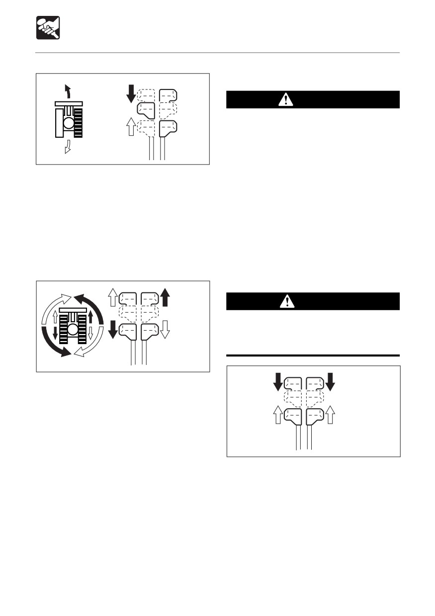
Turning to the left while traveling :
¡If any controls should be touched
a To turn left while traveling forward :
accidentally when the safety lock lever
Set the left lever to neutral.
is lowered, the machine will move
e To turn left while traveling backward :
suddenly, and cause serious injury or
Set the left lever to neutral.
death.
To turn to the right while traveling, operate
¡ < TB153FR > : Note that the dozer blade
the right lever in the same way.
control is not locked, even when the
safety lock lever is set to the lock
Spin Turn
position. Do not touch this control
accidentally.
CAUTION
Neutral
Never bring the machine to a sudden stop
except in the case of a true emergency.
Stop as gently as possible.
E4D019
a To spin left :
Tilt the left lever backward and the right
Neutral
Neutral
lever forward.
e To spin right :
Tilt the right lever backward and the left
lever forward.
E4D020
1. Slowly set the left and right travel levers
to the neutral position. The machine stops.
81
OPERATION
Machine Operation
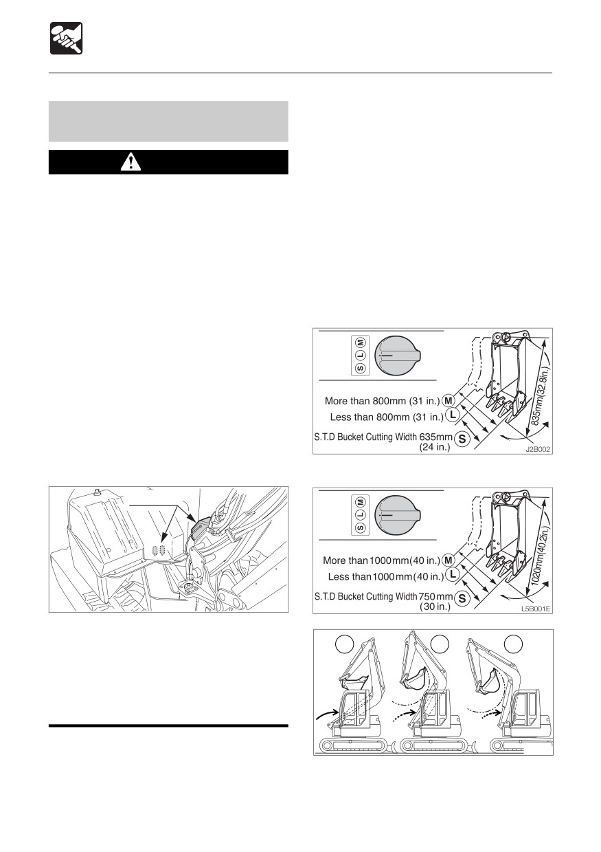
The Attachment Interference Switch (AIS)
Attachment Interference Switch /
allows the operator to select the attachment
Interference Prevention System
size used on the excavator. The Interference
Prevention System uses the operator’s AIS
WARNING
selection to limit the movement of the boom
(raising, lowering, and offsetting) to prevent
¡ All attachments other than a bucket
the cab from being struck by the boom,
should be used with the AIS set to the
attachment, or the material being handled.
M mode.
The Interference Prevention System (IPS)
¡Ensure that all buckets used in the
is automatically set to the M mode when the
standard position are no longer than a
engine is started to provide the maximum
standard bucket when measured from
operator protection.
pin to tooth.
¡ Failure to properly set the Attachment
< TB153FR >
Interference Switch can result in
equipment damage, serious injury, or
death.
¡Do not disassemble or damage the
sensors installed on the boom and
main body. Doing so may cause the
Interference Prevention System to
malfunction. If there is a problem,
contact a Takeuchi sales or service
outlet for inspection or repair.
< TB180FR >
Sensors
J1B018
¡The interference prevention system
may not function properly if
S
L
M
attachments other than Takeuchi
approved attachments are installed.
Do not install other non-approved
attachments.
J1B017
82
OPERATION
Machine Operation
To properly set the AIS :
Reset the AIS to the M position
Select the appropriate attachment width
< TB153FR >
S
Standard bucket attachment less
than 635mm (24 inches) wide
L
Bucket attachment more than
635mm (24 inches) and less than
800mm (31 inches) wide
M
Bucket attachment more than
800mm (31 inches) wide or any other
approved attachment
< TB180FR >
S
Standard bucket attachment less
than 750mm (30 inches) wide
L
Bucket attachment more than
750mm (30 inches) and less than
1000mm (40 inches) wide
M
Bucket attachment more than
1000mm (40 inches) wide or any
other approved attachment
Operate excavator
The minimal front radius feature is only
available for the standard bucket
attachment 635mm (24 inches) TB153FR
/ 750mm (30 inches) TB180FR or smaller.
83
OPERATION
Machine Operation
Operating the Working
Equipment
WARNING
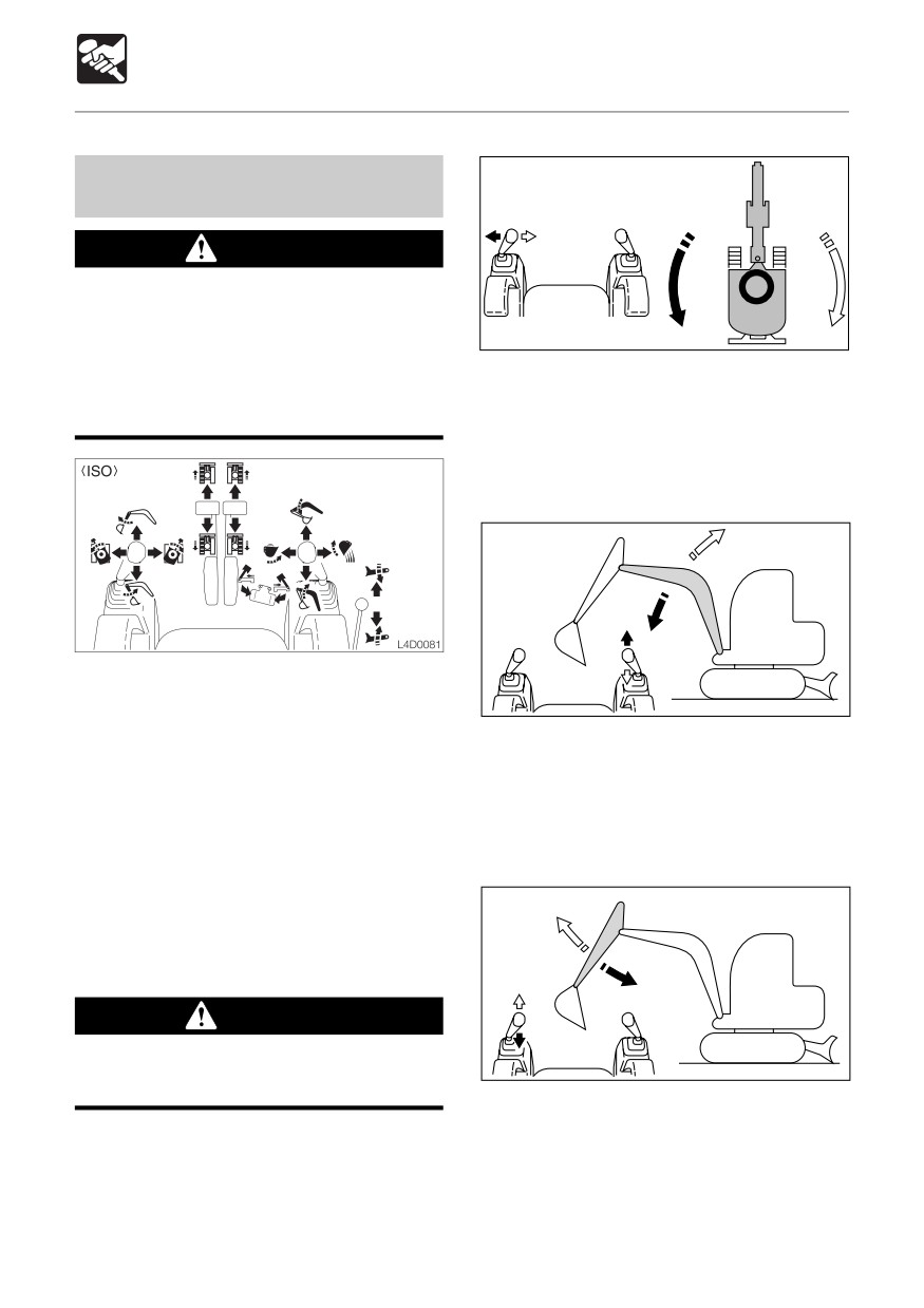
¡ Be careful to check which pattern of
lever control arrangement you are
operating with before beginning
E4D021
operations.
a To slew left :
¡ The explanations in this manual are for
Tilt the left operating lever to the left.
the ISO pattern.
e To slew right :
Tilt the left operating lever to the right.
Operating the Boom
Use the right operating lever to operate the
boom and bucket.
E4D022
Use the left operating lever to operate the
a To lower the boom :
arm and for slewing.
Tilt the right operating lever forward.
Return the operating levers to the neutral
e To raise the boom :
position to stop the hoe attachments.
Tilt the right operating lever backward.
1. Fully lower the safety lock lever to
Operating the Arm
disengage the lock.
2. Raise the pedal lock to disengage the lock.
Slewing
WARNING
Check the surrounding area for safety
E4D023
before slewing.
a To contract the arm :
Tilt the left operating lever backward.
e To extend the arm :
Tilt the left operating lever forward.
84
OPERATION
Machine Operation
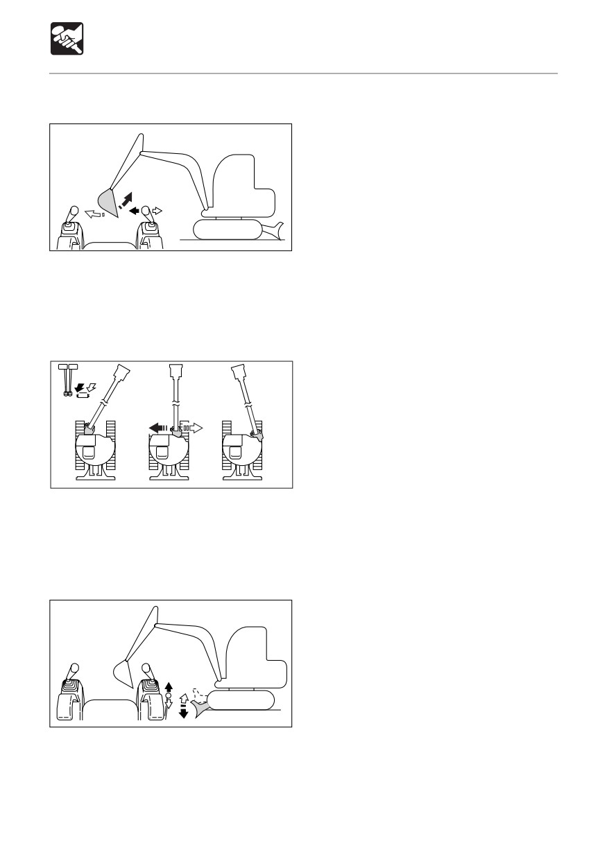
Operating the Bucket
E4D024
a To dig :
Tilt the right operating lever to the left.
e To dump :
Tilt the right operating lever to the right.
Operating the Boom Offset
L2D0061
a To offset left :
Press the left side of the pedal.
e To offset right :
Press the right side of the pedal.
Operating the Dozer Blade
E4D026
a To lower the dozer blade :
Tilt the lever forward.
e To raise the dozer blade :
Tilt the lever backward.
85
OPERATION
Machine Operation
Operating With the Slider Switch
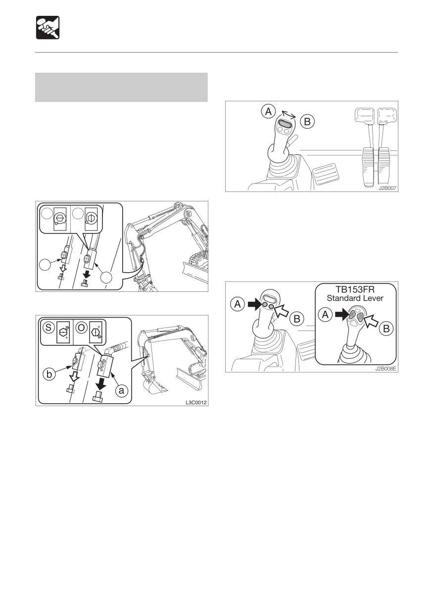
Operating the First Auxiliary
(Proportional Control)
Hydraulics
Use this to operate a breaker, crusher or
other attachment.
Two methods of operation are permitted:
operation with the auxiliary hydraulic buttons
and operation with the slider switch
(proportional control).
< TB153FR >
a To deliver hydraulic oil to port (a):
S
O
Move the switch to the left (A).
e To deliver hydraulic oil to port (b):
Move the switch to the right (B).
Operating With the Auxiliary Hydraulic
b
Buttons
a
J1C002
< TB180FR >
a To deliver hydraulic oil to port (a):
Press (A).
e To deliver hydraulic oil to port (b):
Press (B).
86
MEMO
87
OPERATION
Operating Procedures
Be Gentle on the Hydraulic Cylinders
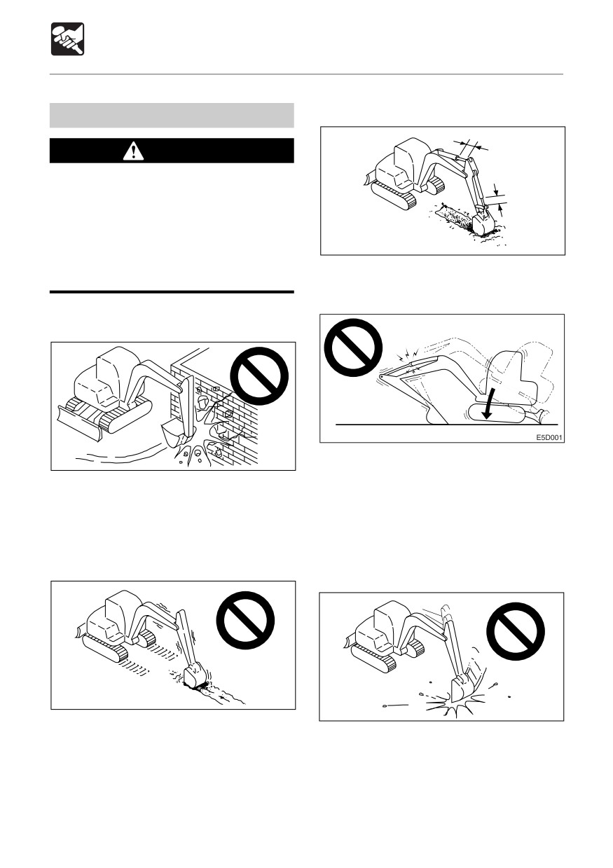
Prohibited Operations
WARNING
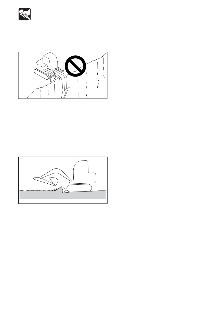
¡ Do not operate on base rock (hard or
soft).
¡ Do not slew (swing) while traveling. If
you must operate the hoe attachment
while traveling, operate at speeds slow
E4D031
enough so you have complete control
Do not extend the hydraulic cylinders to the
at all times.
stroke ends. Operate them with leeway.
Do not perform breaking or leveling
operations using slew force
E4D029
Do not support the machine body with the
hoe attachment as it is lowering with the arm
Do not break down walls or level ground
cylinder fully extended. Doing so
using slew force. Also, do not dig the bucket
concentrates the load on the arm cylinder
teeth into the ground during slewing. Doing
and could damage the arm cylinder.
so will damage the hoe attachment.
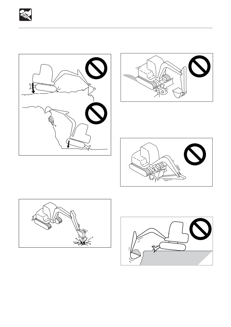
Do not Drive Piles with the Bucket or Dig
Do not Dig while Traveling
with it Using Shock Force
E4D030
E4D032
Do not dig the bucket into the ground and
Doing so will shorten the service life of the
use the traveling force to dig.
hoe attachment. Use hydraulic force to dig.
88
OPERATION
Operating Procedures
Do not Perform Operations Using the
Caution on Exposing the Dozer Blade to
Machine’s Dropping Force
Shocks
E4D040
Hitting the dozer blade against rocks, etc.,
could damage the dozer blade or the blade
cylinder.
Caution on Folding the Hoe Attachment
E4D033
Putting excessive strain on the machine will
shorten its service life. Use the hydraulic
force of the cylinders and always dig with
shallow, long strokes.
E4D041
Digging Base Rock
Be careful not to hit the bucket or dozer blade
when folding the hoe attachment.
Do not use the Dozer Blade as an Outrigger
E4D034
For hard base rock, break the rock up into
small pieces with a breaker, etc., before
N0D009
digging. This prevents damage to the
machine and is thus more economical in the
end.
89
OPERATION
Operating Procedures
Pay Attention to the Dozer Blade when
Digging
E4D0431
When digging deeply with the dozer blade
positioned at the front, be careful that the
boom cylinder and bucket do not hit the dozer
blade.
Operate with the dozer blade at the rear
whenever possible.
Caution on Digging Down with the Dozer
Blade
E4D044
This dozer blade is designed for simple earth
pushing. Do not dig down deeply with the
dozer blade. Doing so could damage the
dozer blade and lower body.
90
OPERATION
Operating Procedures
Cautions on Use in Water
Cautions on Operating
Cautions on Traveling
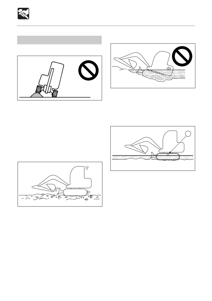
E4D038
If you leave water at a sharp angle, the rear
E4A040
of the machine may be submerged, exposing
the radiator fan to water and damaging them.
Traveling over obstacles (rocks, stumps, etc.)
Do not let the rear of the machine get
may subject the body to strong shocks and
submerged.
result in damage. Avoid traveling over
obstacles whenever possible. If you must do
so, keep the hoe attachment near the ground,
travel at low speed, and go over the obstacle
1
at the center of the crawler.
Cautions on Traveling in 2nd (High)
Speed
E4D039
¡ Allowable water depth
In water, only use the machine up to a
depth at which the water comes up to the
middle of the carrier roller (1).
¡ When greasing places used under water
E4D037
for long periods of time, apply enough
grease so that the old grease is expelled.
On uneven ground, travel at low speed and
¡ Never submerge the slew bearing or main
avoid accelerating, stopping or changing
body in water or sand. If the slew bearing
directions abruptly.
or main body should get submerged,
Also, when traveling in 2nd speed, do so with
contact a Takeuchi sales or service outlet
the dozer blade at the front.
for inspection.
91
OPERATION
Operating Procedures
Traveling Posture
Cautions on Traveling on Slopes
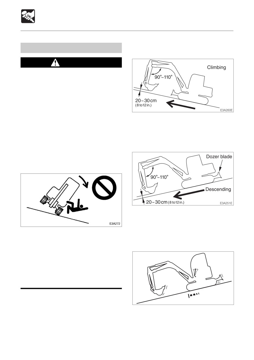
Traveling up slopes
WARNING
¡ Never exceed the machine’s stability
capabilities (maximum gradeability - 30°,
lateral tipping angle - 15°). Also note
that when actual working area
conditions are poor the machine’s
stability capabilities may be lower.
¡ When traveling on slopes or grades,
When traveling up slopes at an angle of 15°
lower the bucket to a height of 20 to 30
or greater, travel in the posture shown in the
cm (8 to 12 in.) off the ground. In
diagram above.
emergencies, lower the bucket to the
ground and stop the machine.
Traveling down slopes
¡ When traveling on slopes or grades,
move slowly in first gear (low speed).
¡ Do not travel down slopes in reverse.
When traveling down slopes at an angle of
15° or greater, lower the engine speed and
travel in the posture shown in the diagram
above.
¡Do not change directions or cross
slopes sideways. First return to a flat
Braking when traveling down slopes
surface then redirect the machine.
¡ On grass, dead leaves, wet metal or
Braking
frozen surfaces, the machine may slide
sideways even on very gentle slopes.
Make sure the machine never faces
sideways with respect to the slope.
D5D028E
When traveling down slopes, the brakes are
applied automatically when the travel levers
are returned to the neutral position.
92
OPERATION
Operating Procedures
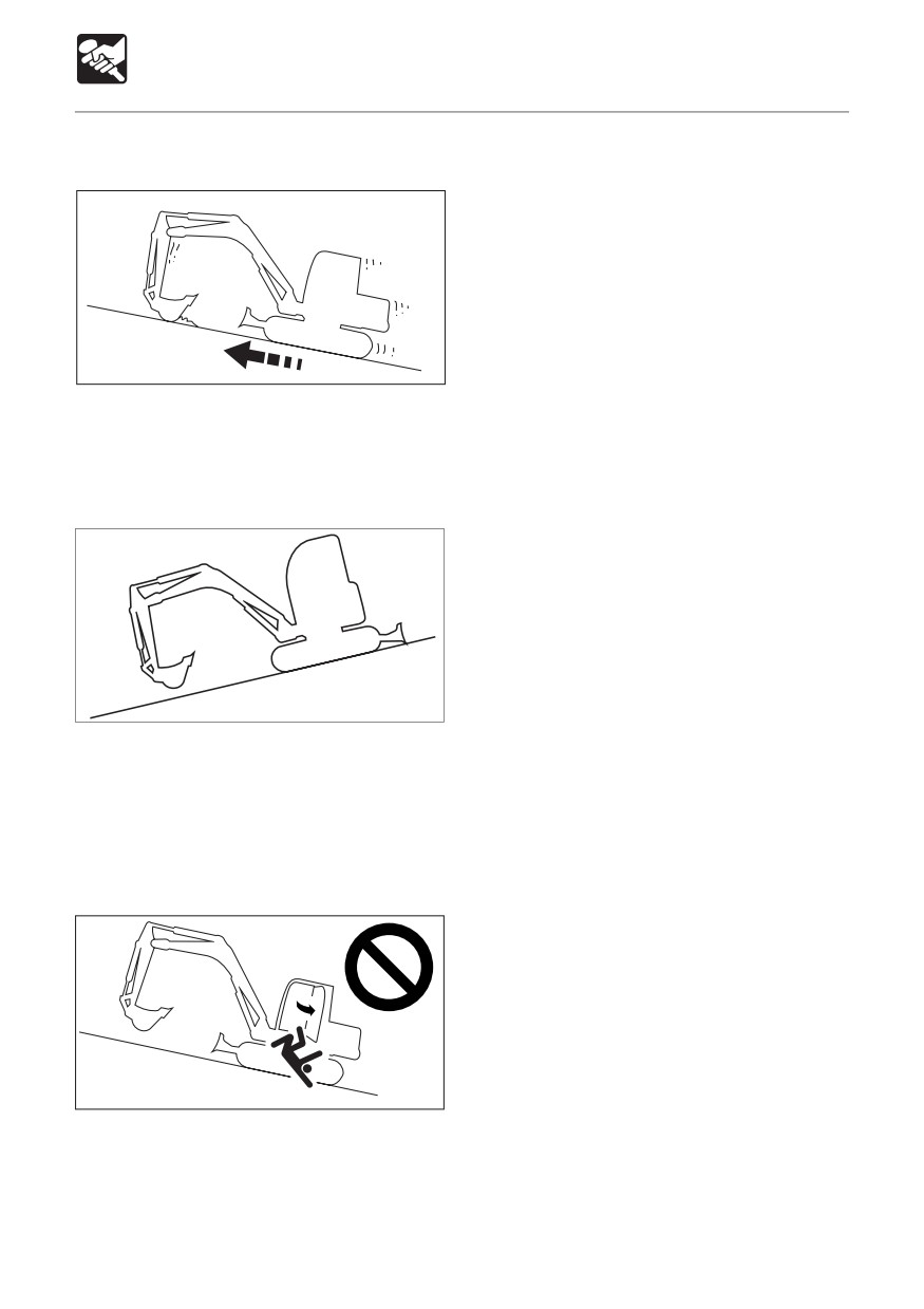
If the crawlers slip
Climbing
E4D046
If the crawlers slip while traveling up a slope,
use the pulling force of the arm to climb the
slope.
If the engine stops
Descending
D5D029E
If the engine stops when traveling down a
slope, set the travel levers to the neutral
position, stop the machine, then start the
engine.
Do not open the door while traveling on
slopes
E4D048
Opening the door while traveling on slopes
is dangerous, as the force required to open
and close the door changes abruptly. Always
keep the door closed when traveling on
slopes.
93
OPERATION
Operating Procedures
Getting Out of Mud
Operations Possible with this
Machine
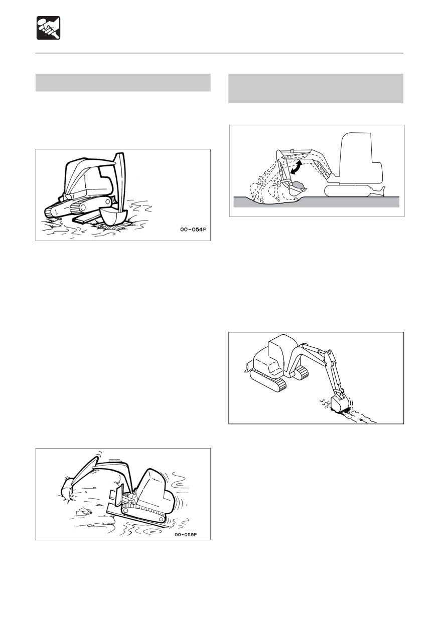
If the machine gets stuck in mud, use the
procedure below to get it out.
Excavating
If one crawler is stuck
80 ~120
E4D0501
1. Set the dozer blade on the side opposite
the side you want to dig on.
1. Slew the bucket to the side which is stuck.
2. Use the arm and bucket and dig with
2. Set the arm and boom to an angle of 90
shallow, long strokes. The digging force
to 110°.
is strongest when the boom and arm angle
3. Press the bottom of the bucket (not the
is 80 to 120°. Use this angle for effective
teeth) against the ground.
digging.
4. Place a plank, etc., under the lifted crawler.
5. Lift the bucket and slowly move out of the
Digging Ditches
mud.
If both crawlers are stuck
1. Perform steps 1 to 4 above for both
crawlers.
2. Dig the bucket into the ground in front of
the machine.
3. Pull with the arm and travel forward
E4D051
simultaneously to slowly move out of the
mud.
Mount a bucket suited for digging ditches and
set the crawlers parallel to the ditch to be
dug for greater efficiency.
When digging wide ditches, dig the sides first,
the center later.
94
OPERATION
Operating Procedures
Digging Side Ditches
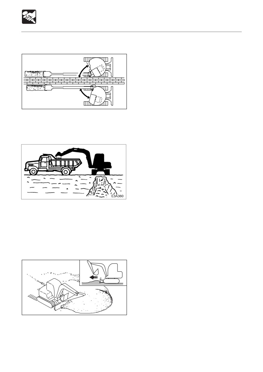
3. Once the mound is low, remove the dirt
from the top. If the load on the body is too
heavy, adjust by raising or lowering the
60°
dozer blade.
75°
E4D052
Use the boom swing function to dig side
ditches as shown in the diagram.
Loading
When loading dirt in a truck, starting from
the back of the truck’s bed makes for easier
loading and increases the amount of dirt that
can be loaded.
Also, use a small slewing angle for greater
efficiency.
Leveling
E4D053
1. Bring the hoe attachment close to the
body.
2. Gradually remove the dirt from the side of
the mound.
95
OPERATION
Parking the Machine
Parking
Inspection and Checks After
Stopping the Engine
WARNING
1. Check for oil and water leakage and
inspect the working equipment, covers
and lower body. If any irregularities are
found, repair.
2. Fill the fuel tank.
Refer to page 122 “Inspecting the Fuel
Level”.
3. Remove any paper scraps or dirt from the
engine room.
E3A4901
4. Remove any mud from the lower body.
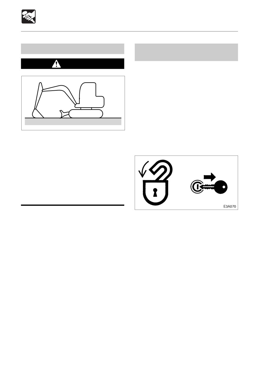
¡ Park the machine on firm, level ground
Locking
and apply the parking device.
Be sure to lock the following places :
¡Before leaving the operator’s seat,
raise the safety lock lever to engage
the lock and stop the engine. If any
controls should be touched
accidentally when the safety lock lever
is lowered, the machine will move
suddenly, and cause serious injury or
death.
1. Set the left and right travel levers to the
¡ Cab door
neutral position.
¡ Fuel filler cap
2. Return the throttle lever or controller and
¡ Rear cover
idle the engine at low speed.
¡ Tool box
3. Lower the bucket and dozer blade to the
¡ Manual storage compartment (Canopy)
ground.
4. Raise the safety lock lever to engage the
lock.
5. Stop the engine and remove the key.
Refer to page 71 or 73 “Stopping the
Engine”.
96
OPERATION
Handling in Cold Weather
Preparing for Cold Weather
Cautions after Completing
Operations
In cold weather, it may be difficult to start the
engine and the coolant may freeze. Make
Heed the following in order to prevent dirt,
the preparations described below.
water, or other objects stuck on the machine
as well as the lower body from freezing :
Changing the Fuel and Lubricant
¡ Remove any dirt or water from the body.
Change the fuel, hydraulic oil and engine oil
In particular, water droplets on the
to types suited for cold conditions.
hydraulic cylinder rod surfaces could
Refer to page 110 “Lubricant and Fuel Chart”.
freeze, and if dirt enters into the seals
along with this, the seals could break.
¡ Park the machine on a dry, hard surface.
Engine Coolant
If no appropriate place can be found, put
boards down and park the machine on
WARNING
them.
¡Drain any water from the fuel tank to
The coolant is combustible. Keep flames
prevent freezing.
away.
Refer to page 132 “Draining the Fuel
Tank”.
Use long-life coolant (antifreeze) and tap
¡ To prevent decreased battery
water for the engine coolant.
performance, place a cover over the
Supplement: New machines are delivered
battery or remove it from the machine and
with JIS Type 2 long-life coolant (antifreeze)
store it in a warm place.
at a concentration of 50%.
Also add battery fluid before starting the
Refer to page 110 “Lubricant and Fuel Chart”.
next morning. If battery fluid is added after
completing operations, the distilled water
Battery
may not mix, resulting in freezing.
As the temperature drops, the battery
performance decreases.
Inspect the battery. If the charge is low,
After Cold Weather is Over
contact a Takeuchi sales or service outlet to
have the battery charged.
Perform the following after cold weather is
Refer to page 131 “Inspecting the Battery
over :
Fluid Level and Replenishing”.
¡Change the fuel and the oils for the
different devices with those specified on
the Lubricant and Fuel Chart.
Refer to page 110 “Lubricant and Fuel
Chart”.
¡ When using one-season type antifreeze
coolant, completely drain the antifreeze
coolant, carefully clean the inside of the
coolant system, then add tap water.
Refer to page 138 “Cleaning the Engine
Cooling System”.
97
OPERATION
Handling Rubber Crawlers
Rubber crawlers have an inherent weakness
due to their use of rubber. Be sure to heed
the prohibitions and cautions below so as to
prevent damage to the crawlers and crawler
slippage.
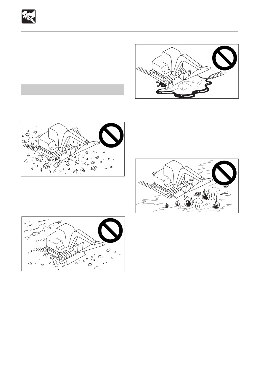
Prohibited Actions
E4D057
Do not travel or operate the machine in the
¡ Do not let fuel, oil, salt or chemical solvents
following places :
get on the crawlers. These substances
may corrode the couplings of the crawlers’
metal cores, resulting in rust or peeling. If
these substances should get on the
crawlers, wipe them off immediately using
water.
E4D056
¡ Traveling or slewing on broken stone,
jagged base rock, iron rods, iron scraps
or the edges of iron sheets may damage
or cut the crawlers.
E4D058
¡ Traveling on roads directly after asphalting
or on hot surfaces such as over fires or
on iron sheets under strong sunlight may
result in irregular wear or damage of the
lugs.
¡ Do not move earth in places where the
rubber crawlers may slip. Doing so may
E4D055
speed up lug wear.
¡ Traveling on riverbeds or places with many
soft rocks may cause the crawlers to slip
off or be damaged due to rocks getting
stuck in them.
¡ Do not use on the seashore. The salt may
corrode the metal cores.
98
OPERATION
Handling Rubber Crawlers
¡ When storing the rubber crawlers for long
Cautions
periods of time (3 months or more), do so
indoors in a place not exposed to direct
Heed the following cautions when operating
sunlight or rain.
the machine :
L4D013
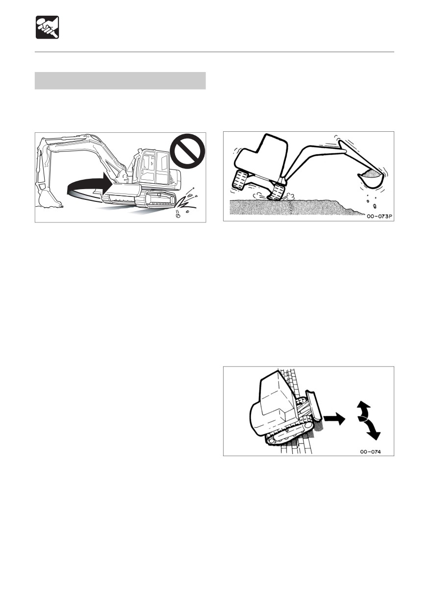
¡ Rubber crawler belts are not as stable as
¡ Do not turn the undercarriage with the front
steel crawler belts since the entire lug is
of the machine body lifted using the hoe
rubber. Be very careful when slewing and
attachment and the upperstructure left in
swinging sideways.
this posture. Doing so will twist the crawler
with the load concentrated on a single
Preventing the Rubber Crawlers from
point on the crawler belt, rapidly leading
Slipping Off
to damage.
Heed the following in order to prevent the
¡Avoid changing course abruptly and
rubber crawlers from slipping off:
spinning on concrete surfaces whenever
¡ Always keep the crawlers at the proper
possible.
tension.
Doing so may wear or damage the rubber
crawlers.
¡ Avoid drops that may expose the rubber
crawlers to strong shocks.
¡Salt, potassium chloride, ammonium
sulfate, potassium sulfate, and triple
superphosphate of lime can damage the
crawler belts. If any of these substances
should get on the crawler belts, wash them
off thoroughly with water.
¡ Do not let the sides of the rubber crawlers
¡ When traveling up large cobblestone or
rub against concrete or walls.
rock steps (20 cm (8 in.) or greater), climb
¡ Do not damage the rubber crawlers by
up the step at a direct angle and do not
hitting the bucket against them.
change course on top of the step.
¡Be especially careful in the winter on
snowy or frozen surfaces as the crawler
belts tend to slip.
¡ Use rubber crawler belts at temperatures
between -25°C to +55°C (-14°F to 131°F).
99
OPERATION
Handling Rubber Crawlers
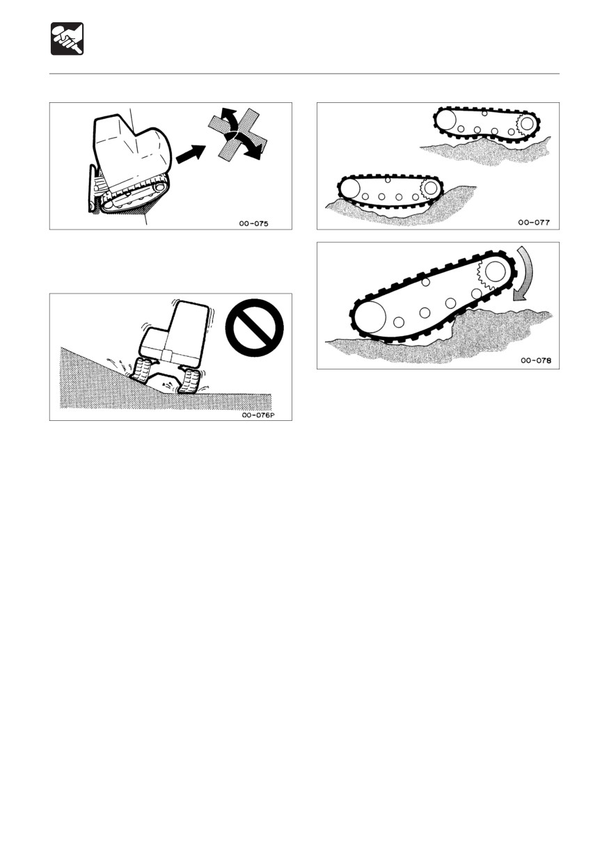
¡ When climbing in reverse, do not change
course at the point where the slope starts.
¡ Do not change directions when the crawler
belts are slack as shown in the diagram.
¡ Avoid traveling with one crawler on a slope
or projecting object and the other crawler
on a flat surface (with the machine at a tilt
of 10° or greater). Travel with both crawlers
on flat surfaces.
100
TRANSPORT
Loading and Unloading
102
Hoisting the Machine < TB153FR >
103
Hoisting the Machine < TB180FR >
104
Securing the Machine
105
Cautions on Transporting
105
101
TRANSPORT
Loading and Unloading
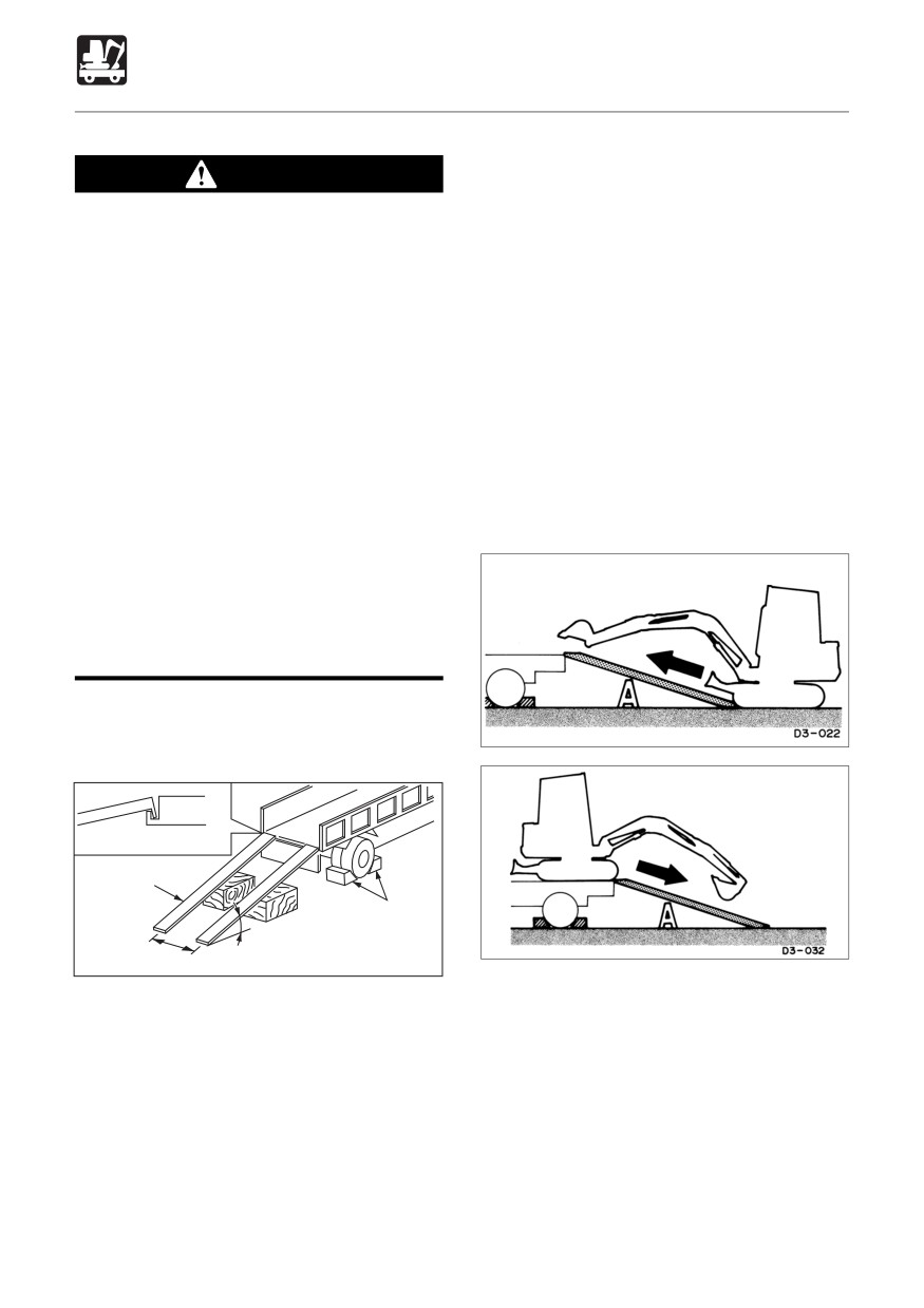
1. Apply the truck’s parking brake and place
WARNING
stoppers against its tires.
2. Fasten the ramps securely to the truck bed
The machine may roll or tip over or fall
so that they will not come off. Set the
while loading or unloading it. Take the
ramps to an angle of 15° or less.
following precautions :
3. Line up the center of the truck bed with
¡ Select a firm, level surface and keep
the center of the machine and the center
sufficient distance from road
of the ramps with the center of the
shoulders.
crawlers.
¡Use loading ramps of adequate
4. Make sure the dozer blade does not hit
strength and size. Maintain the slope
the ramps.
of loading ramps within 15 degrees.
5. Lower the hoe attachment as much as
¡ Keep the truck bed and loading ramps
possible, making sure it will not hit the
clean of oil, clay, ice, snow, and other
truck.
materials which can become slippery.
6. Lower the engine speed.
Clean the tracks.
¡ Never change course on the ramp.
¡Do not slew (swing) on ramps. The
machine may tip over.
¡ When slewing (swinging) on the truck
bed, do so slowly as the footing can
be unstable.
When loading or unloading the machine, be
sure to use ramps and following the
procedure below.
Fasten to the suspension fitting
Ramp
Stopper
15° or less
Distance between ramps
E4F001
7. Determine the direction on the ramps, then
slowly travel up or down the ramps in 1st
speed (low speed), following the signals
of a flagman.
8. Load the machine properly at the
prescribed position on the bed.
Refer to page 105 “Transporting Posture”.
102
TRANSPORT
Hoisting the Machine < TB153FR>
Hoisting
WARNING
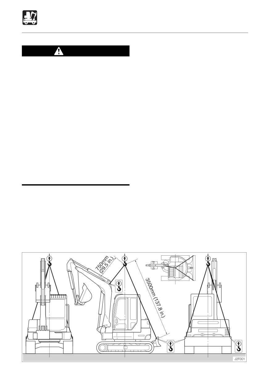
1. Slew the upper structure so that the dozer
¡ Know and use correct crane signals.
blade is positioned to the rear of the body
¡ Inspect the hoisting equipment daily
(so that the crawler frame and upper
for damaged or missing parts.
structure are parallel).
¡ When hoisting, use a wire rope with
2. Raise the dozer blade fully.
sufficient strength with respect to the
3. Fully extend the bucket and arm cylinders
machine’s weight.
and fully raise the boom.
¡Do not hoist with the machine in a
4. If the boom is swung to either the left or
posture other than the one described
right side, set it so that it is straight ahead.
in the procedure below. Doing so is
5. Raise the safety lock lever to engage the
dangerous as it may result in the
lock.
machine losing its balance.
6. Stop the engine and remove the starter
¡Do not hoist the machine with an
key and get off the machine.
operator (s) on it.
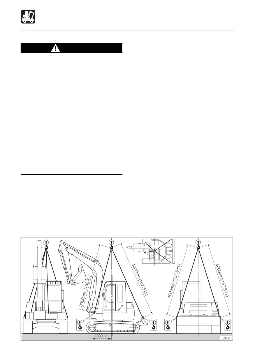
7. Install the sling as shown on the diagram
¡ When hoisting, hoist slowly so that the
below.
machine does not tip.
Suspend in such a way that the sling and
¡ Keep all other persons out of the area
Lifting tool do not touch the body.
when hoisting. Do not move the
8. Hoist slowly until the machine just leaves
machine over the heads of the persons.
the ground.
9. Stop hoisting until the machine is stable
IMPORTANT: This hoisting method
and hoist slowly.
applles to machines with standard
specifications.
The center of gravity differs according to
the attachments and options that are
mounted.
Consult a Takeuchi sales or service outlet.
Hoisting posture
103
TRANSPORT
Hoisting the Machine < TB180FR>
Hoisting
WARNING
1. Slew the upper structure so that the dozer
¡ Know and use correct crane signals.
blade is positioned to the rear of the body
¡ Inspect the hoisting equipment daily
(so that the crawler frame and upper
for damaged or missing parts.
structure are parallel).
¡ When hoisting, use a wire rope with
2. Raise the dozer blade fully.
sufficient strength with respect to the
3. Fully extend the bucket and arm cylinders
machine’s weight.
and fully raise the boom.
¡Do not hoist with the machine in a
4. If the boom is swung to either the left or
posture other than the one described
right side, set it so that it is straight ahead.
in the procedure below. Doing so is
5. Raise the safety lock lever to engage the
dangerous as it may result in the
lock.
machine losing its balance.
6. Stop the engine and remove the starter
¡Do not hoist the machine with an
key and get off the machine.
operator (s) on it.
7. Install the sling as shown on the diagram
¡ When hoisting, hoist slowly so that the
below.
machine does not tip.
Suspend in such a way that the sling and
¡ Keep all other persons out of the area
Lifting tool do not touch the body.
when hoisting. Do not move the
8. Hoist slowly until the machine just leaves
machine over the heads of the persons.
the ground.
9. Stop hoisting until the machine is stable
IMPORTANT: This hoisting method
and hoist slowly.
applles to machines with standard
specifications.
The center of gravity differs according to
the attachments and options that are
mounted.
Consult a Takeuchi sales or service outlet.
Hoisting posture
104
TRANSPORT
Securing the Machine
Cautions on Transporting
After loading the machine in the designated
position, secure it as described below.
Transporting Posture
1. Lower the blade.
WARNING
2. Fully extend the bucket and arm cylinders,
then lower the boom.
¡Know and follow the safety rules,
3. Stop the engine and remove the starter
vehicle code and traffic laws when
key.
transporting the machine.
4. Raise the safety lock lever to engage the
¡ Consider the length, width, height and
lock.
weight of the truck with the machine
5. Set stoppers in front and behind the
loaded on it when determining the best
crawlers.
route.
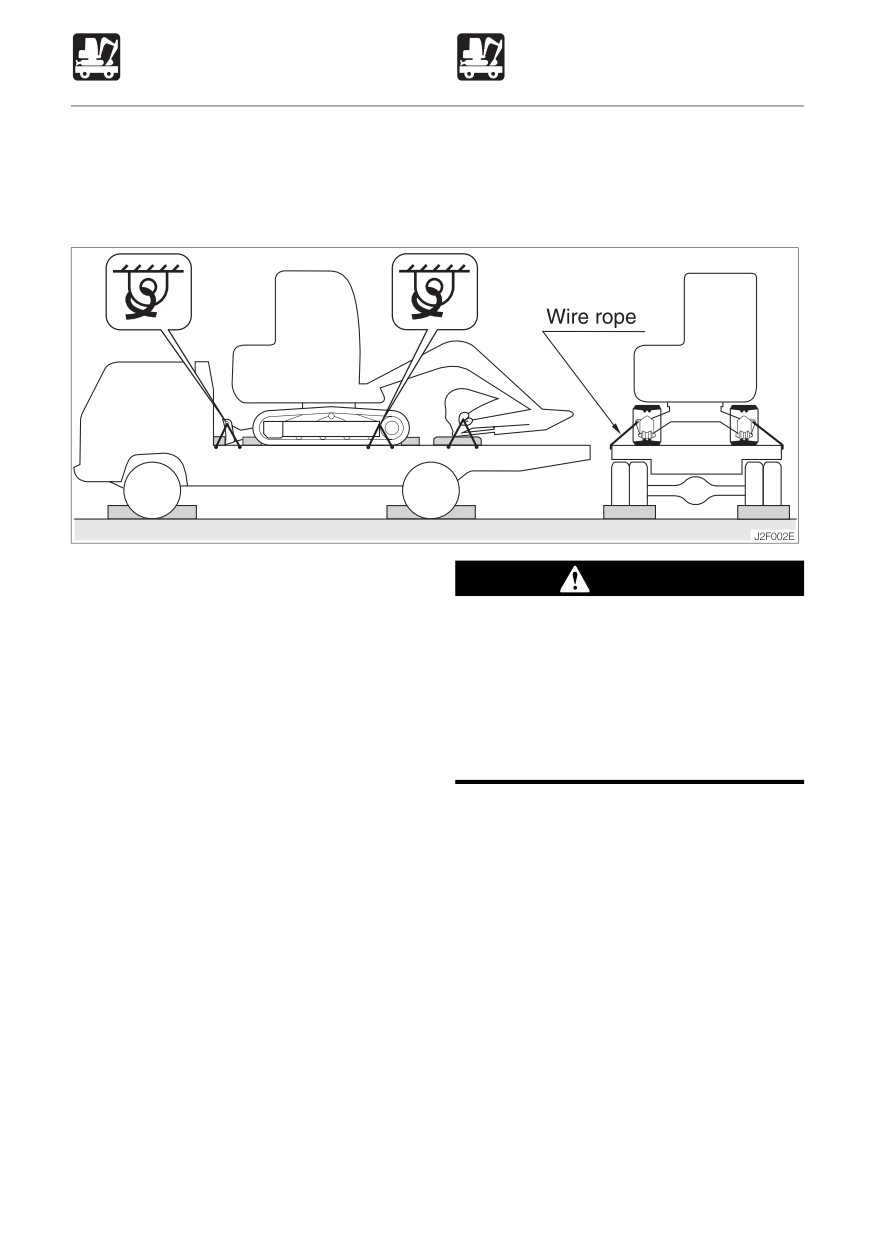
6. Put a chain or wire rope over the lower
frame and fasten it securely to prevent
sideways slippage.
7. Secure the bucket with a chain or wire
rope.
IMPORTANT: Place a wooden block
under the bucket so that it is not damaged
by hitting the floor.
105
106
MAINTENANCE
General
108
Service Data
110
Important Parts
115
Maintenance Chart
116
Walk-Around Inspection
118
Daily Inspection (Every 10 Hours)
120
After First 50 Hours
(New Machines Only)
125
Every 50 Hours
128
After First 250 Hours
(New Machines Only)
133
Every 250 Hours
134
Every 500 Hours
137
Every 1000 Hours
138
Every 2000 Hours
142
When Required
145
Long-term Storage
160
107
MAINTENANCE
General
Maintenance Description
Cautions on Maintenance
For long-term use of the machine under good
Do not perform inspection and maintenance
conditions, perform the inspection and
procedures not prescribed in this manual.
maintenance procedures properly and safely
Have inspection and maintenance
as recommended in this manual.
procedures not prescribed in this manual
performed by a Takeuchi sales or service
The inspection and maintenance items are
outlet.
divided according to the machine’s total
operating time (inspection and maintenance
Always keep the machine clean.
to be performed every 10 hours (walk-around
¡ Always keep the machine clean, and wash
and daily inspection), every 50 hours, every
it before performing inspection and
250 hours, etc.). Refer to the hour meter to
maintenance.
determine when it is time to perform
¡ When washing the machine with water,
inspection and maintenance. Items for which
stop the engine and cover the electrical
it is not possible to determine the inspection
system with plastic to protect it from water.
and maintenance interval are included under
Exposing the electrical system to water is
“When Required”.
dangerous and could result in short-
circuits or malfunction. Do not wash the
When operating the machine in extremely
battery, sensors, connectors or the inside
harsh environments (with high dust levels or
of the cab with water or steam.
high temperatures), inspection and
maintenance should be performed earlier
Fuel, lubricant and grease
than the times indicated on the Maintenance
¡ For fuels, lubricant and grease, follow the
Chart.
instructions on the “Lubricant and Fuel
Chart”.
¡ Use pure fuels, lubricants and greases
which do not contain water, and be careful
to keep dirt out when changing or
replenishing fuel, lubricant or grease.
¡ Store fuels, lubricants and greases in the
prescribed places and in such a way that
no water or dirt can get in them.
Cautions on fueling
¡If the port includes a strainer, do not
remove the strainer when fueling.
¡ After fueling, be sure to securely tighten
the cap, etc.
¡Do not add more than the prescribed
amount of fuel.
108
MAINTENANCE
General
Do not clean parts with fuel.
Disposing of wastes
Do not use fuel to clean parts. Use a non-
¡ Collect spent fluids from the machine in
combustible cleaning agent.
containers. Disposing of wastes
irresponsibly damages the environment.
Keep dirt out.
¡ Dispose of oil, fuel, cooling water, coolant,
When mounting and removing parts, do so
filters, batteries and other harmful
in a place where there is no dust, clean the
substances as prescribed by law.
working area and the part, and keep dirt out.
Check after maintenance
Clean mounting surfaces.
¡ Gradually increase the engine speed from
When mounting and removing parts, be sure
a low idle to maximum speed and check
that the surfaces of contact of the parts are
that there is no oil or water leaking from
clean. If the sealing grooves of the surface
serviced parts.
of contact are damaged, consult a Takeuchi
¡ Operate all the operating levers and check
sales or service outlet.
that the machine is operating properly.
Seals and split pins
Cautions on handling of battery cables
¡ Replace removed seals and split pins with
¡ Disconnect the battery cables (+,-) before
new ones.
working on the electrical system or doing
¡ When mounting, be careful not to damage
any welding.
or twist the seal.
Remove the negative (-) battery cable first.
When reconnecting the battery, connect
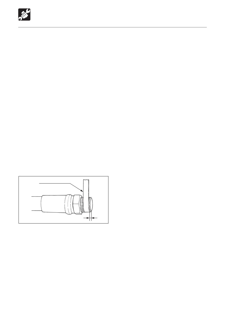
Sealing tape
the negative (-) battery cable last.
¡ Do not disconnect the battery cables while
Sealing tape
the engine is running. Doing so could
damage the electronic circuitry of the
alternator and other parts.
Leave 1 or 2 threads free
E4G001
¡When wrapping sealing tape around
plugs, etc., remove any old sealing tape
from the threads and clean the threads.
¡ Wrap the sealing tape tight, leaving 1 or 2
threads at the tip free.
109
MAINTENANCE
Service Data
Lubricant and Fuel Chart
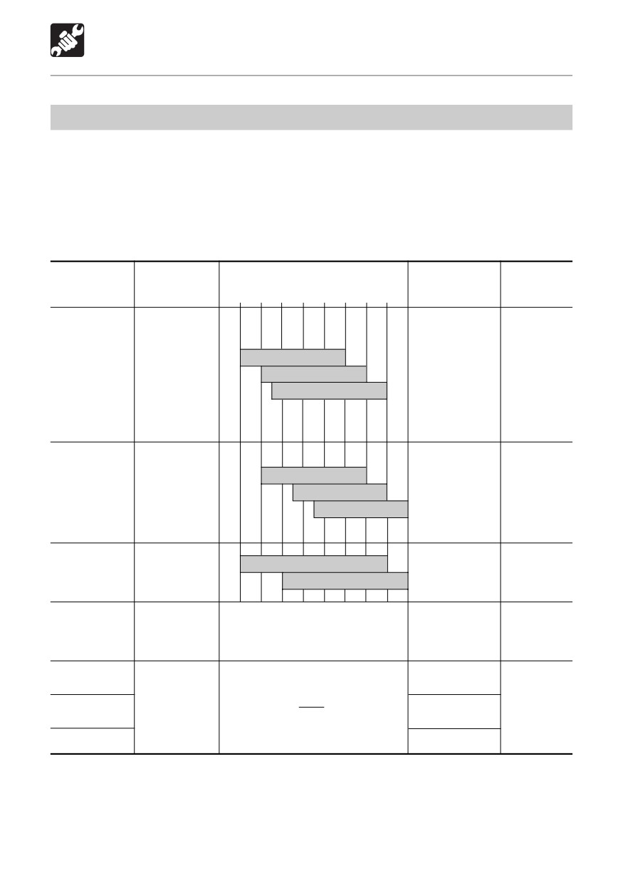
Use different lubricants, greases and fuels according to the temperature, referring to the
chart below.
¡ Change the lubricant earlier than as shown in the table if it is extremely dirty or its
performance has deteriorated severely.
¡ Whenever possible, use the same brand of lubricant as before. If changing with a different
brand, replace the entire quantity - do not mix different brands.
Lubricants and greases
Type by temperature
Replacement
Capacity
Part
Type
-22
-4
14 32 50 68 86 104°F
interval
R(US. qt.)
-30 -20 -10
0
10 20 30 40 °C
Upper limit:
<TB153FR>
7.4
(7.8)
<TB180FR>
Diesel
SAE 5W-20
Engine
After first 50 hrs.
10.2
(10.8)
engine oil
SAE 10W-30
oil pan
Every 250 hrs.
Lower limit:
API - CD
SAE 15W-40
<TB153FR>
4.0
(4.2)
<TB180FR>
5.7
(6.0)
System:
<TB153FR>
ISO VG32
110 (29.1 US.gal.)
Hydraulic
Antiwear
<TB180FR>
ISO VG46
Every 2000 hrs.
tank
hydraulic oil
120 (31.7 US.gal.)
ISO VG68
Tank: 68
(18.1 US.gal.)
<TB153FR>
Engine
Coolant
50% coolant mixture
8.4
(8.9)
cooling
(water +
Every 1000 hrs.
30% coolant mixture
<TB180FR>
system
coolant) **
9.5 (10)
<TB153FR>
Travel
After first 250
Gear oil
1.0
(1.06)
reduction
SAE 90
hrs.*
API-GL-4
<TB180FR>
gear
Every 1000 hrs.
1.5
(1.6)
Slew
Lithium
Every 50 hrs.
bearing
based
Working
Daily or every
grease
As required
equipment
10 hrs.
EP-2
Levers
NLGI No. 2
When required
: If the percentage of the traveling time within the total operating time is high, replace the
gear oil earlier than the specified time.
** : For water, use tap water (soft). Do not use well or river water.
When the ambient temperature drops below 0°C, add coolant (antifreeze). Follow the
coolant manufacturer’s instructions to determine the mixture ratio.
110
MAINTENANCE
Service Data
Fuel
Capacity
Part
Type
R(US. gal.)
Use a clean, Quality fuel for good performance
and optimum engine life.
¡ To prevent fuel flow problems in cold weather,
<TB153FR>
use diesel fuel with a pour point of at least -
60 (15.9)
Fuel tank
Diesel fuel
12°C (10°F) below the lowest expected ambient
<TB180FR>
temperature.
92 (24.3)
¡ Minimum cetane number is 45. Low temperature
or high altitude operation may require the use
of fuel with a higher cetane number.
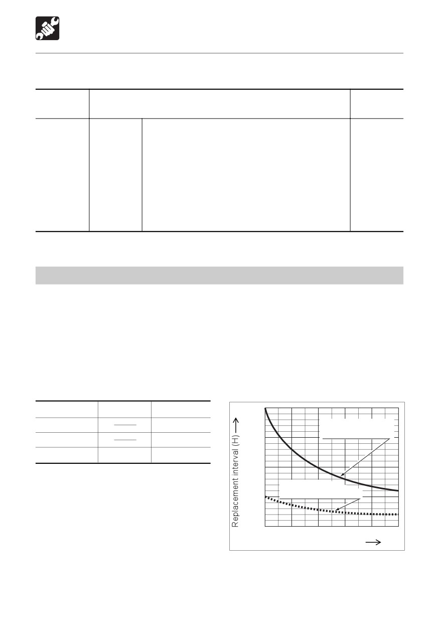
Replace the hydraulic oil regularly!
When using a hydraulic breaker, the oil deteriorates quicker than during normal digging. Be
sure to replace the hydraulic oil and return filter element.
¡ Failure to replace these in time can lead to damage to the machine and breaker’s hydraulic
systems. In order to improve the service life of the hydraulic systems, be sure to replace
the hydraulic oil and return filter element according to the following chart of the replacement
interval.
¡ Clean the suction strainer when changing the return filter element.
Replacement Interval (Hours)
2000
Item
Hydraulic Oil
Filter Element
1st time
25
Replacement interval
for hydraulic oil
1500
2nd time
100
Periodically
600
200
1000
When the breaker operating ratio is 100%
Refer to page 200 “Hydraulic Breaker”.
Replacement
interval for filter element
500
0
20
40
60
80
100
Breaker operating ratio (%)
N0G036
111

MAINTENANCE
Service Data
Expendables
Replace expendables such as filters and elements periodically, referring to the table below.
Item
Part name
Part No.
Replacement interval
Return filter
Element
15511-02600
After first 50 hrs.
Every 500 hrs.
Fuel filter
Cartridge
119802-55800
Every 500 hrs.
Engine oil filter
Cartridge
<TB153FR>
After first 50 hrs.
129150-35152
Every 250 hrs.
<TB180FR>
129150-35151
Air cleaner
Element (outer)
<TB153FR>
Every 1000 hrs.
119808-12520
or after 6 cleanings
<TB180FR>
(whichever comes first)
129062-12560
Inner Element
<TB153FR>
Every 1000 hrs.
(option)
19111-02772
or after 3 cleanings of
<TB180FR>
the outer element
19111-07692
(whichever comes first)
Air breather filter
Element
15520-00902
Every 1000 hrs.
112
MAINTENANCE
Service Data
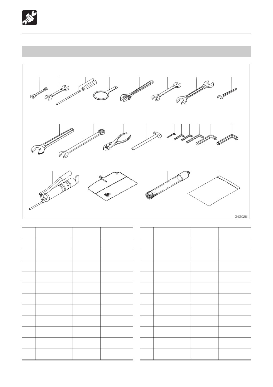
Tools
1
2
3
4
6
7
8
9
10
11
12
13
14 15 16
17
18
19
20
21
22
23
No.
Part name
Part No.
Remarks
No.
Part name
Part No.
Remarks
1
Spanner
19100-47081
10-12
13
Hammer
16903-00330
3/4
2
Spanner
19100-47082
14-17
14
Hex. wrench
16906-00400
4mm
3
Screwdriver
19100-06112
(+) (-)
15
Hex. wrench
16906-00500
5mm
4
Filter wrench
19100-65081
16
Hex. wrench
16906-00600
6mm
6
Monkey wrench
16904-00250
250mm
17
Hex. wrench
16906-00800
8mm
7
Spanner
16900-01922
19-22
18
Hex. wrench
16906-01000
10mm
8
Spanner
16900-02427
24-27
19
Hex. wrench
16906-01400
14mm
16910-60610
TB153FR
9
Spanner
16901-00013
13
20
Grease gun
16910-60600
TB180FR
10
Spanner
16901-00041
41
21
Tool case
16914-00001
Drain connector
15545-12601
TB153FR
11
Spanner
16909-00026
26
22
for EU
15545-12600
TB180FR
12
Pliers
16905-00200
200mm
23
Case
16919-00001
113
MAINTENANCE
Service Data
Tightening Torques
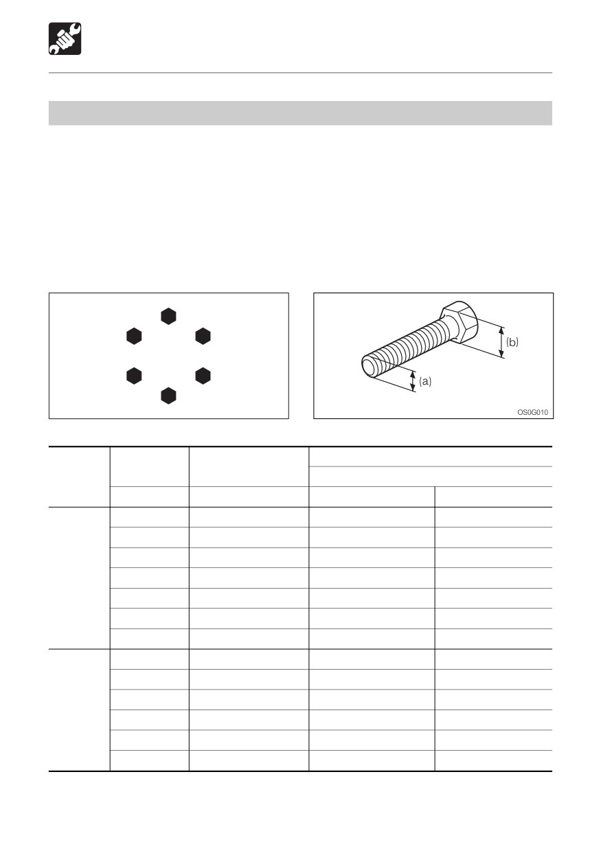
Nuts and Bolts (for ISO strength category 10.9)
Tighten nuts and bolts at the torques shown on the table below, unless otherwise specified in
the text.
¡ Tightening torques when mounting plastic covers differ from the values on the table below.
Consult a Takeuchi sales or service outlet. Tightening too strongly will break the cover.
¡ When replacing nuts and bolts, replace them with nuts and bolts of the same size and
standards.
¡ Tighten nuts and bolts alternately (top, bottom, left then right) or in 2 or 3 times so that they
are tightened uniformly.
1
3
6
5
4
2
E4G003
Torque
Head width
Size (a) X Pitch
Thread
(b)
General Connection Points
mm
mm
N·m
ft-lb
10
M6 X 1.0
9.8 ± 0.5
7.2 ± 0.4
12, 13
M8 X 1.25
22.6 ± 1.1
16.6 ± 0.8
14, 17
M10 X 1.5
47.1 ± 2.4
34.7 ± 1.7
Coarse
17, 19
M12 X 1.75
83.4 ± 4.1
61.5 ± 3.0
19, 22
M14 X 2.0
134.4 ± 6.7
99.1 ± 4.9
22, 24
M16 X 2.0
207.9 ± 10.4
153.3 ± 7.7
27, 30
M20 X 2.5
410.9 ± 20.5
303.1 ± 15.1
12, 13
M8 X 1.0
24.5 ± 1.2
18.1 ± 0.9
14, 17
M10 X 1.25
50 ± 2.5
36.9 ± 1.8
17, 19
M12 X 1.5
87.3 ± 4.3
64.4 ± 3.2
Fine
19, 22
M14 X 1.5
135.3 ± 6.8
99.8 ± 5.0
22, 24
M16 X 1.5
220.6 ± 11
162.7 ± 8.1
27, 30
M20 X 1.5
452.1 ± 22.6
333.4 ± 16.6
114
MAINTENANCE
Important Parts
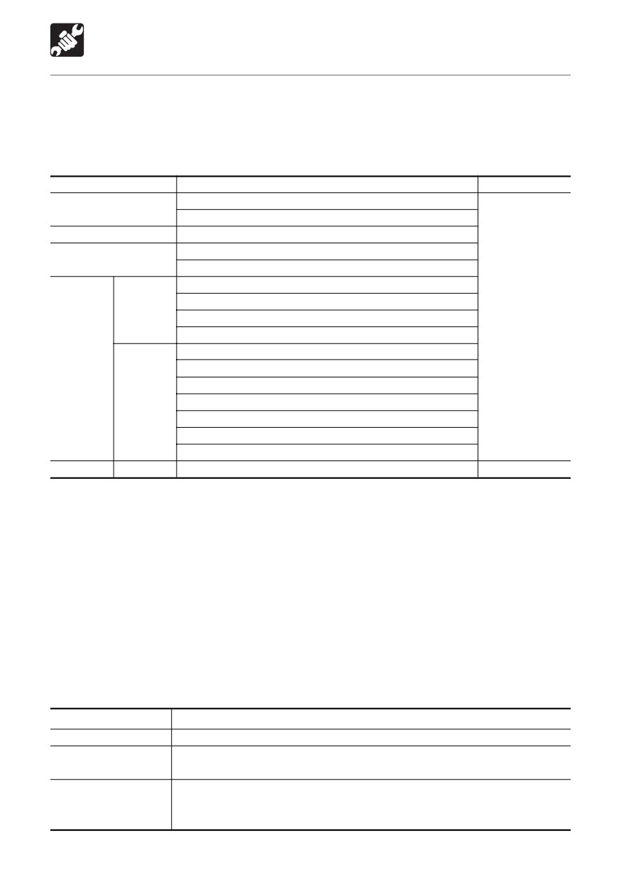
For safe use, the machine must be serviced periodically. To increase safety, periodically
replace the parts listed in the following table of important parts.
Serious injury or a fire could result if they deteriorate or are damaged.
Table of Important Parts
Unit
Important parts to be replaced periodically
Replacement Interval
Fuel hoses
Fuel system
Packing in fuel filler cap
Engine connection
Engine oil filter hoses
Heater hoses
Heater & AC systems
Air conditioner hoses
Hydraulic hoses ( Pump - delivery )
Machine
Hydraulic hoses ( Pump - suction )
body
Hydraulic hoses ( Slew motor )
Every 2 years
Hydraulic hoses ( Travel motor )
Hydraulic hoses ( Boom cylinder lines )
Hydraulic
Hydraulic hoses ( Arm cylinder lines)
system
Hydraulic hoses ( Bucket cylinder lines )
Working
Hydraulic hoses ( Offset cylinder )
equipment
Hydraulic hoses ( Blade cylinder )
Hydraulic hoses ( Pilot valve )
Hydraulic hoses ( Auxiliary lines )
Seat belt
Every 3 years
Above important parts are vulnerable to aging and wear or deterioration and it is difficult to
determine the degree to which they have deteriorated on the occasion of periodic service. To
maintain their proper function at all times, therefore, replace them with new ones after using
them for a specific period of time even if no abnormality is found with the parts. If you find
abnormalities in these parts before their scheduled replacement time is reached, repair or
replace them immediately. If a hose clamp is deformed or cracked, replace it immediately.
When replacing the important parts, please contact a Takeuchi sales or service outlet .
Also check the hydraulic hoses other than the above important parts. If any abnormality is
found in them, retighten them or replace them immediately.
When replacing the hydraulic hoses, replace the O-rings and seals at the same time.
Check the fuel and hydraulic hoses according to the periodic schedule described below.
Refer to “Maintenance”.
Type of inspection
Inspection item
Daily inspection
Leakages from joints, hydraulic or fuel hoses.
Monthly inspection
Leakages from joints, hydraulic or fuel hoses.
Damaged hydraulic or fuel hoses (cracks, wear and tear).
Annual inspection
Leakages from joints, hydraulic or fuel hoses.
Deteriorated, twisted, damaged hydraulic or fuel hoses (cracks, wear
and tear) or hoses in contact with other parts of the machine.
115
MAINTENANCE
Maintenance Chart
Maintenance Items
See page
Walk-Around Inspection
Inspecting by opening the engine hood and covers
118
Inspecting by walking around the machine
119
Inspecting while sitting in the operator’s seat
119
Daily Inspection (Every 10 Hours)
Inspecting and replenishing the coolant
120
Inspecting and replenishing the engine oil
121
Inspecting the water separator
121
Inspecting the fuel level
122
Inspecting the hydraulic oil level and replenishing
122
Lubricating the working equipment
124
After First 50 Hours (New Machines Only)
Replacing the hydraulic oil return filter
125
Replacing the engine oil and oil filter
126
Inspecting and adjusting the fan belt
127
Every 50 Hours
Inspecting and adjusting the crawler tension
128
Lubricating the slew bearing
130
Inspecting the battery fluid level and replenishing
131
Draining the fuel tank
132
After First 250 Hours (New Machines Only)
Replacing the travel motor gear oil*
133
Every 250 Hours
Replacing the engine oil and oil filter
134
Inspecting and adjusting the fan belt
134
Cleaning the air cleaner
134
Cleaning the radiator fins and oil cooler fins
136
*
If the percentage of the traveling time within the total operating time is high, replace the
gear oil earlier than the specified time.
116
MAINTENANCE
Maintenance Chart
Maintenance Items
See page
Every 500 Hours
Replacing the hydraulic oil return filter
137
Replacing the fuel filter
137
Every 1000 Hours
Cleaning the engine cooling system
138
Replacing the air cleaner element
140
Replacing the air breather filter
141
Replacing the travel motor gear oil
141
Inspecting and adjusting the engine valve clearance
141
Retightening the engine cylinder head bolts
141
Inspecting the engine fuel injection pressure and spray condition
141
Every 2000 Hours
Replacing the hydraulic oil and cleaning the suction strainer
142
Inspecting the engine fuel injection timing
144
Inspecting the engine fuel injection valve
144
When Required
Inspecting and replenishing the windshield washer fluid
145
Cleaning the water separator
145
Lubricating the levers
146
Adjusting the gap between the bucket and arm < TB180FR >
147
Replacing the bucket
148
Replacing the bucket teeth and the side cutters < TB153FR >
150
Replacing the bucket teeth and the side cutters < TB180FR >
152
Tilting up the platform
154
Inspecting the rubber crawlers
155
Replacing the rubber crawlers < TB153FR >
156
Replacing the rubber crawlers < TB180FR >
158
117
MAINTENANCE
Walk-Around Inspection
Perform the following inspections once every day before starting the engine the first time.
WARNING
¡ Before operating, perform the walk-around inspections and make repairs immediately
should any irregularities be found.
¡ Be sure to secure the engine hood or cover when opening it. Do not open the engine
hood or cover on slopes or in strong wind.
Before starting the engine, look around the machine and lower body, clean any combustible
materials off high temperature parts of the engine, and inspect for such irregularities as oil
leakage, water leakage and looseness of nuts and bolts.
Inspecting by Opening the
Engine Hood and Covers
1. Check for any twigs, leaves, oil or other
3. Check for oil leakage from the hydraulic
combustible materials around the engine
tank, hydraulic devices, hoses and
and battery.
connections.
2. Check for oil or engine coolant water
leakage around the engine.
118
MAINTENANCE
Walk-Around Inspection
Inspecting by Walking Around
Inspecting While Sitting in the
the Machine
Operator’s Seat
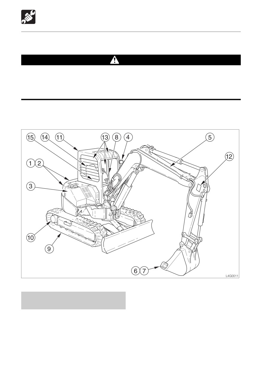
4. Check lights for dirt, damage and burnt
13. Check the windshield for dirt or damage.
out bulbs.
14. Check the seat and seat belt for dirt or
5. Check attachments and hoses for
damage.
damage.
Check the operator’s seat for dirt, oil or
6. Check the bucket, bucket teeth and side
other combustible materials.
cutter for wear, damage and looseness.
15. Check the monitor, instruments and
7. Check the hook, slip stopper and hook
switches for dirt or damage.
mount of buckets with hooks for damage.
(Option)
8. Check the handrail and step for damage
and loose bolts.
9. Check the crawler, carrier roller, track
roller, idler and sprocket for damage, wear
and loose bolts.
10. Check for oil leakage from the travel
motor.
11. Check the canopy, cab and guard for
damage and loose nuts and bolts.
Check the rear view mirror and room
mirror for dirt, damage, and angle
adjustment.
12. Check the labels for dirt and damage.
119