Takeuchi Hydraulic Excavator TB153FR (No.15820004~), TB180FR (17830004~). Operator's Manual - page 2
CONTROLS
Doors and Covers
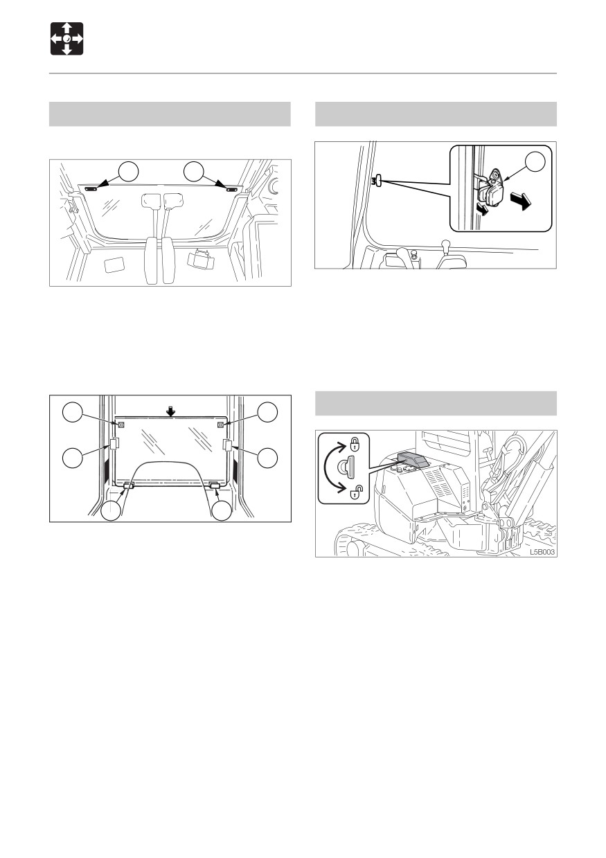
Lower Front Window (Cab)
Side Window (Cab)
Removing
7
N0B023
1. Grasp the catch (7), unlock it and open
1. Open the front window and stow it in the
the side window.
ceiling.
2. To close the side window, close it until a
2. Grasp the protruding parts (4) on the left
click is heard.
and right with your fingers and slowly lift
the lower front window off.
Tool Case
4
4
5
5
6
6
C4C006
3. Hold the glass firmly, place the lower front
window through the guides (5) at the rear,
then set it on the supports (6) and fasten
Lock and unlock
it in place.
1. Insert and turn the starter key
counterclockwise (clockwise) to unlock
(lock).
40
CONTROLS
Doors and Covers
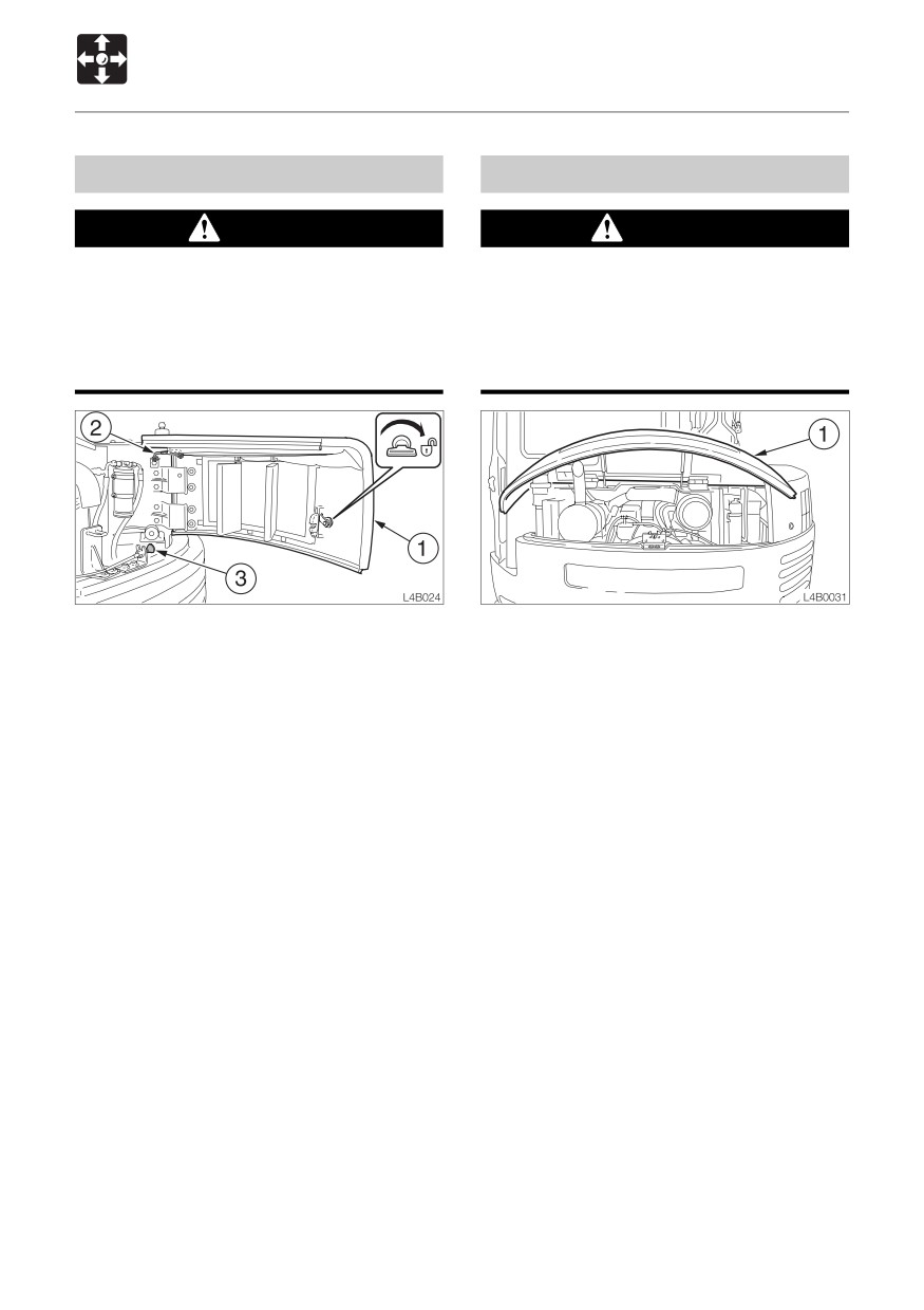
Rear Cover
Engine Hood
CAUTION
WARNING
¡When opening the rear cover, open it Before opening the engine hood, be sure
firmly to the locked position.
to stop the engine. If your hands or tools
¡When opening and closing the rear should get caught in the fan or fan belt
cover, be careful not to get your hands
while the engine is running they may be
or other parts of your body caught.
severed.
Opening
Opening
1. Insert the starter key and turn it clockwise
1. Open the rear cover and pull the unlock
to unlock the rear cover (1).
knob (3).
2. Open the rear cover (1) fully until it stops.
Refer to “Rear Cover”.
(It locks automatically)
2. Lift the engine hood (1) fully.
3. Check that the rear cover (1) is securely
locked in place.
Closing
Engine hood unlock knob (3) is located
1. Close the engine hood and press it down
behind the rear cover (1).
until a click is heard at the front.
Closing
1. Raise the stay (2) to unlock the rear cover
(1).
2. Close the rear cover (1) and press it inside
until a click is heard at the front.
41
CONTROLS
Doors and Covers
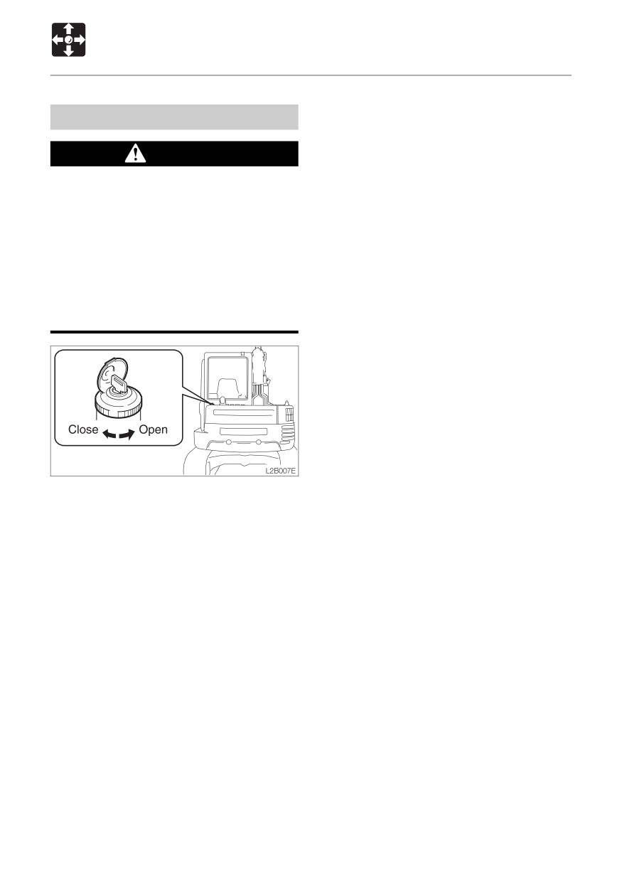
Fuel Filler Cap
WARNING
¡ Do not smoke or permit open flames
while fueling or near fueling
operations.
¡ Supply fuel in a well ventilated place
and with the engine stopped.
¡ Clean up spilled fuel immediately.
¡ Do not fill the fuel tank to capacity.
Allow room for expansion.
¡ Tighten the fuel filler cap securely.
Opening
1. Open the key cover, insert and turn the
key counterclockwise to unlock the fuel
cap.
2. Turn the fuel cap counterclockwise and
remove it.
Closing
1. Set the fuel cap in place and turn it
clockwise.
2. Turn the key clockwise to lock the fuel cap,
then remove the key.
42
MEMO
43
CONTROLS
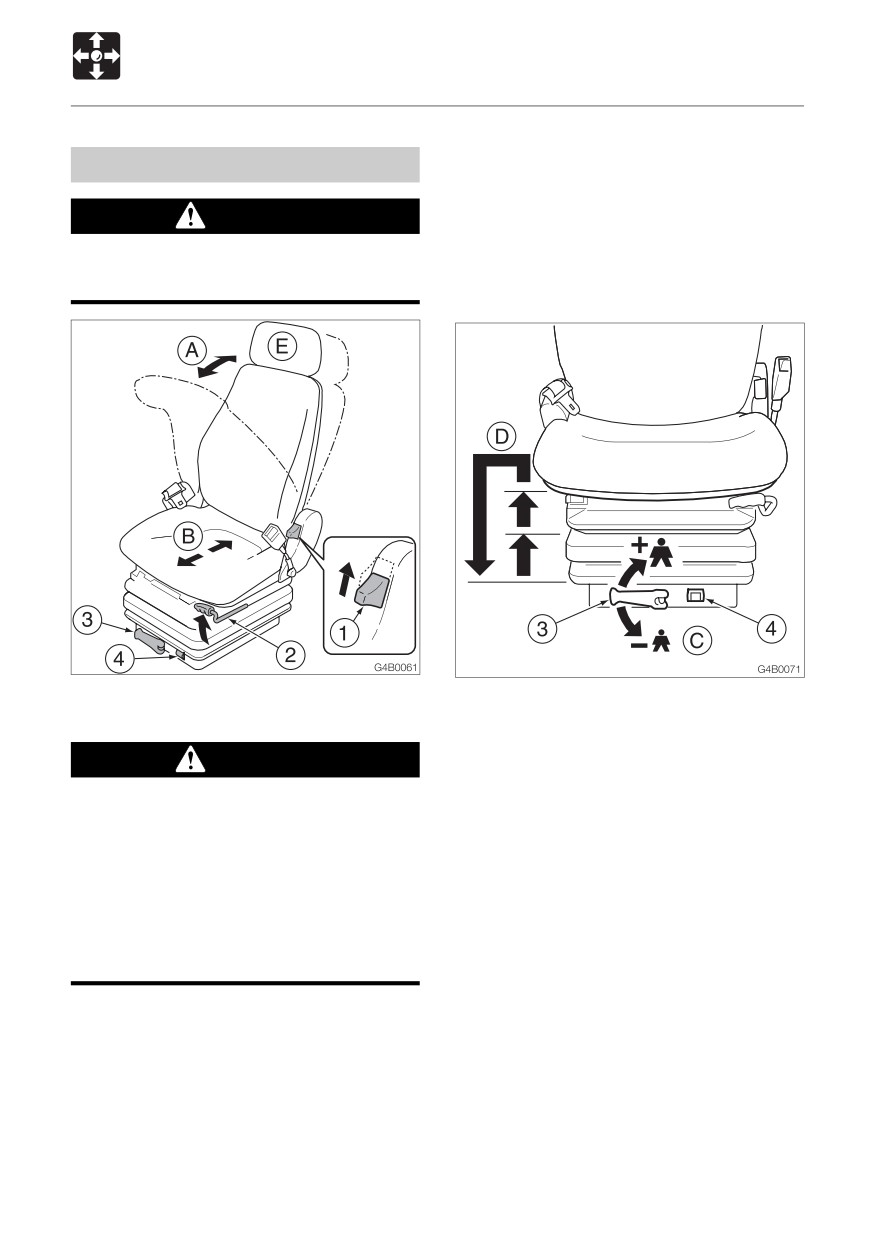
Seat and Seat Belt
(B) Fore-and-aft adjustment
Seat
1. Pull on lever (2) and slide the seat backward
or forward to bring it to the optimum position
WARNING
for operating the machine.
2. Release the lever (2) at the desired position
Adjust, secure and latch the operator’s
and the seat will be locked there.
seat.
Adjustment stroke: 15 steps,150 mm (5.9 in.)
(C) Weight adjustment
(A) Back angle adjustment
1. Turn handle (3) until the indicator (4) will
show the operator’s weight.
WARNING
May be set to any value from 10 kg steps,
¡Do not set the seat back to its
50 to 130 kg (110 to 287 lbs.)
maximum reclining position and slide
(D) Adjusting the height of the seat
the seat backwards at the same time.
Upward
Doing so may break the rear window
1. Lift the seat to first or second position click-
glass, resulting in injury.
stop.
¡ Be careful not to allow the force of the
Downward
spring to bring the seat back sharply
1. First lift the seat to highest position, then
forward.
the seat can be lowered to lowest position.
(E) Headrest adjustment (Option)
1. Raising your torso, sitting down firmly in
The position of the headrest can be adjusted
the seat.
in the vertical and front/back directions.
2. Pulling lever (1) allows you to use the
1. To adjust in the vertical direction, grasp
pressure of the springs in the seat pressing
the headrest with both hands and move it
against your back to adjust the reclining
upwards or downwards.
angle of the seat back. Release the lever
2. To adjust in the front/back direction, grasp
(1) at the desired angle and the seat back
the headrest with hands and move it
will be locked in that position.
forwards or backwards.
44
CONTROLS
Seat and Seat Belt
Seat Belt
CAUTION
Always fasten the seat belt securely
before starting the engine.
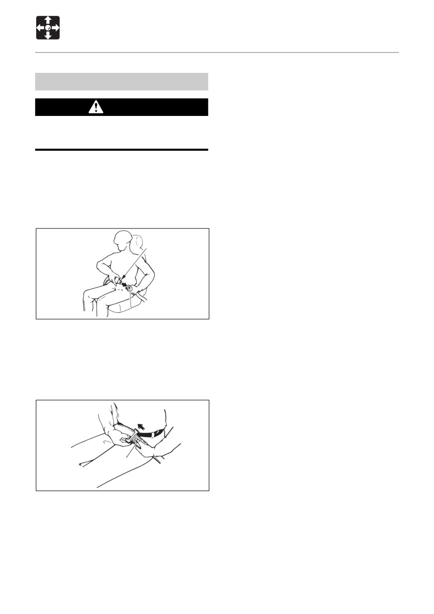
Fastening the seat belt
1. Adjust the seat to the optimum position
for operating, raise your torso, and sit back
firmly into the seat.
2. Pull the seat belt to the desired length.
A
B
E4B023
3. Make sure that the belt is not twisted and
then insert the tongue plate (A) into the
buckle (B) of the seat belt until you hear a
clicking sound as it locks in place.
Releasing the seat belt
C
E4B024
1. To remove the seat belt, simply press the
button (C) located on the buckle.
The seat belt is automatically stowed
away.
45
CONTROLS
Instrument Cluster
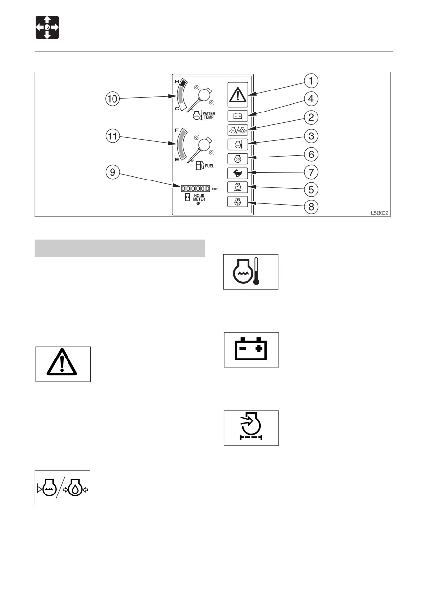
3. Coolant Temperature Warning Lamp
Warning Lamps
This lamp flashes and an
IMPORTANT: If a warning lamp flashes
alarm is sounded if the
and an alarm is sounded, stop all
engine coolant temperature
C4B012
operations immediately and inspect and
rises abnormally while the
maintain the appropriate part.
engine is running.
Refer to page 169 “Troubleshooting”.
4. Battery Charge Warning Lamp
1. Engine Emergency Lamp
This lamp flashes and an
This lamp flashes and an
alarm is sounded if a
alarm is sounded if the
problem arises in the
C4B030
engine oil pressure or the
charging system while the
G4B009
engine is running.
coolant level in the radiator
drops or the coolant temperature rises
abnormally while the engine is running. After
5. Air Cleaner Warning Lamp
approximately 5 seconds, the engine stops
This lamp flashes and an
or low idling automatically.
alarm is sounded if the air
cleaner filter is clogged while
G4B010
2. Engine Oil Pressure / Coolant Level
the engine is running.
Warning Lamp
This lamp flashes and an
alarm is sounded if the
lubricant oil pressure or
L3B036
coolant level in the radiator
drops abnormally while the engine is running.
46
CONTROLS
Instrument Cluster
Indicators
Meters
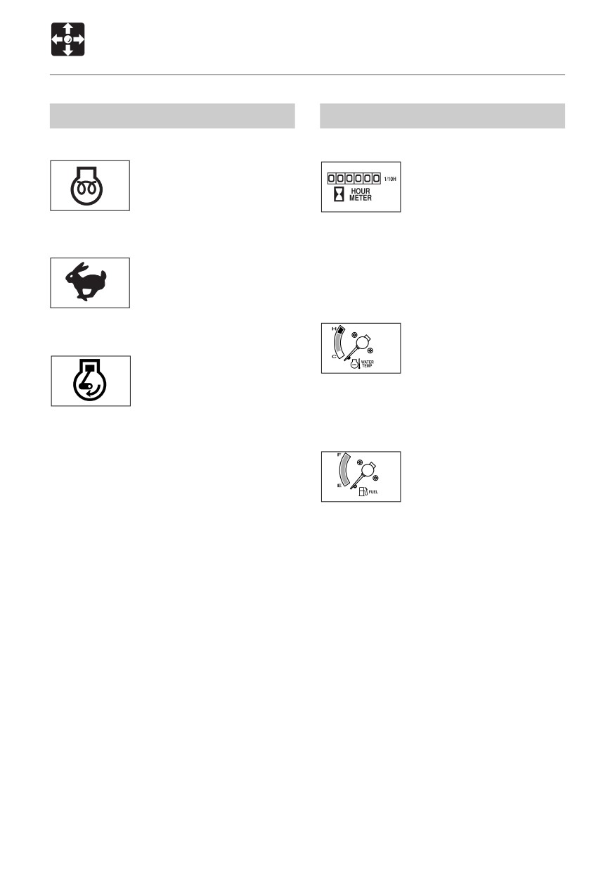
6. Glow Lamp
9. Hour Meter
This lamp turns off when
This displays the total
engine preheating is
engine running time in
completed.
hours.
C4B013
G4B012
The rightmost digit indicates
tenths of hours (6 minutes).
7. Travel Speed Lamp
Set the inspection and maintenance intervals
This lamp lights when the
according to the time displayed on the hour
travel speed is set to 2nd
meter.
(high speed).
C4B014
10. Water Temperature Gauge
This gauge indicates the
8. Decel. Lamp
temperature of the engine
This lamp lights when decel.
coolant water.
G4B013
switch pressed, the engine
The needle should be within
speed decreases.
the green range during machine operation.
G4B011
The red range indicates overheating.
11. Fuel Gauge
This gauge indicates the
amount of fuel in the tank.
Be sure to top off the tank
G4B014
before running out of fuel.
47
CONTROLS
Switches
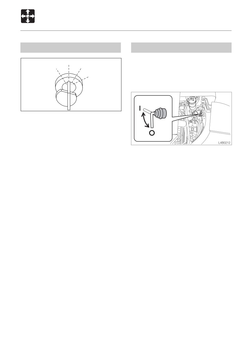
Starter Switch
Battery Switch
OFF
IMPORTANT: Never set this switch to the
PREHEAT
ON
OFF (O) position while the engine is
START
running. Doing so might cause damage
to the electrical system.
E4B010
IMPORTANT: Do not repeatedly switch
the key from OFF to ON and ON to OFF
over a short period. Doing so will cause
engine breakdown.
PREHEAT
Position for preheating the
1. Open the rear cover.
engine.
OFF
Position for stopping the
OFF (O)
Switches off the electrical
engine and inserting or
circuit.Be sure to set this switch
removing the key.
to the OFF (O) position when
ON
Position in which the engine
storing the machine for a long
is running. At this position, all
period, or when performing
the electrical equipment is
maintenance of the electrical
functional.
system.
START
Position for starting the
ON ( I )
Connects the electrical system.
engine. When the key is
Check that this switch is in the
released, the switch
ON ( I ) position before starting
automatically returns to the
the engine.
ON position.
Supplement: Setting this switch to the OFF
(O) position will shut down all of the electrical
circuits and the memory of the radio preset
tuning buttons will be deleted.
48
CONTROLS
Switches
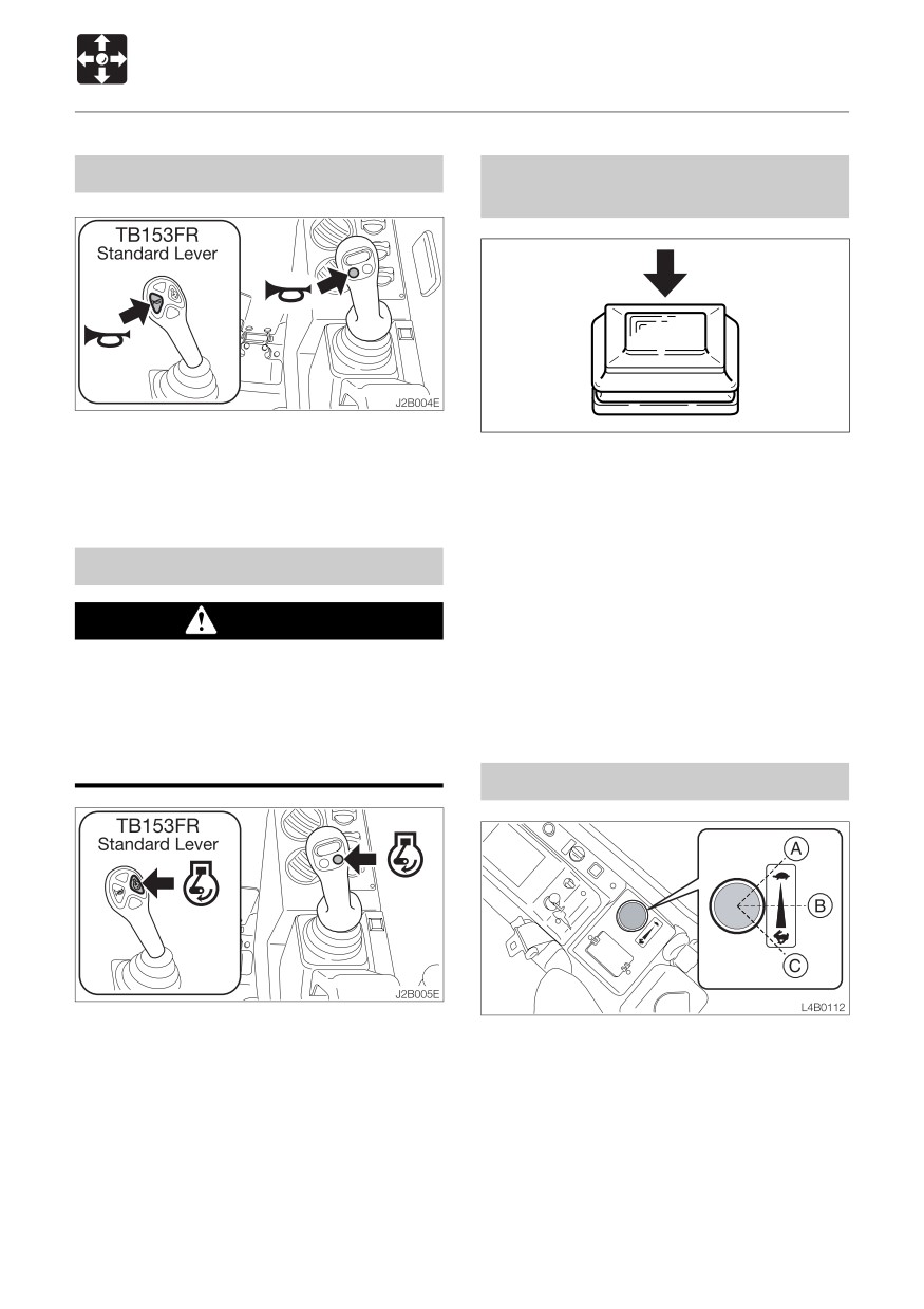
Horn Button
Automatic Decel. Button
< TB180FR >
Press the button on the right operating lever
to blow the horn.
Pressing this button to the ON position will
cause the lamp to light and will activate the
deceleration function. Use of the deceleration
button will not be possible at this time. After
about 4 seconds with the control levers set
Decel. Button
to neutral, the engine speed will automatically
drop to Low idling to reduce fuel
WARNING
consumption. Moving the control levers will
cause the speed to return to the original
Set the operating and travel levers to
engine speed.
neutral before operating the decel. button.
The machine’s operating speed will
change abruptly if the switch is operated
while the levers are engaged.
Throttle Controller < TB180FR >
Press the button on the right operating lever
This controls the engine speed.
to lower the engine speed to low idling.
(A)
Low idling
Press the button again to return to the engine
(B)
Middle speed
speed set with the throttle controler.
(C)
Maximum speed
Supplement: The one-touch decelerator is
a device for lowering the engine speed and
reducing fuel consumption when little engine
output is required, for example when the
operating and travel levers are in neutral.
49
CONTROLS
Switches
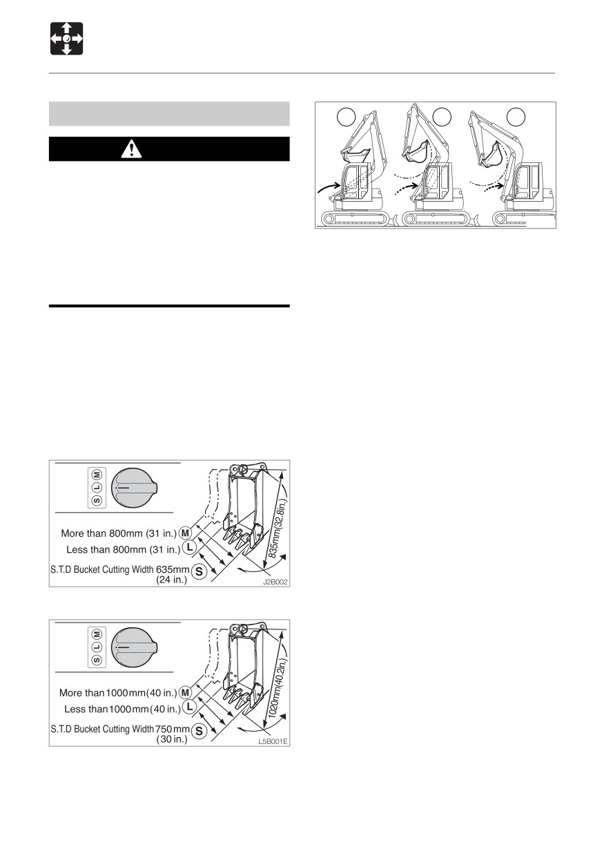
Attachment Interference Switch
S
L
M
WARNING
¡ Failure to properly set the Attachment
Interference Switch can result in
equipment damage, serious injury, or
death.
J1B017
¡Ensure that all buckets used in the
Modes of Operation
standard position are no longer than a
< TB153FR >
standard bucket when measured from
S
Standard bucket attachment less
pin to tooth.
than 635mm (24 inches) wide
L
Bucket attachment more than
The Attachment Interference Switch (AIS) is
635mm (24 inches) and less than
automatically set to the M mode by the
800mm (31 inches) wide
interference Prevention System (IPS) when
M
Bucket attachment more than
the engine is started.
800mm (31 inches) wide or any other
To use the minimal front radius feature, reset
approved attachment
the AIS to the M position then select the
appropriate attachment width (S.L or M).
< TB180FR >
S
Standard bucket attachment less
< TB153FR >
than 750mm (30 inches) wide
L
Bucket attachment more than
750mm (30 inches) and less than
1000mm (40 inches) wide
M
Bucket attachment more than
1000mm (40 inches) wide or any
other approved attachment
Refer to page 82 “Attachment Interference
Switch / Interference Prevention System”.
< TB180FR >
50
CONTROLS
Switches
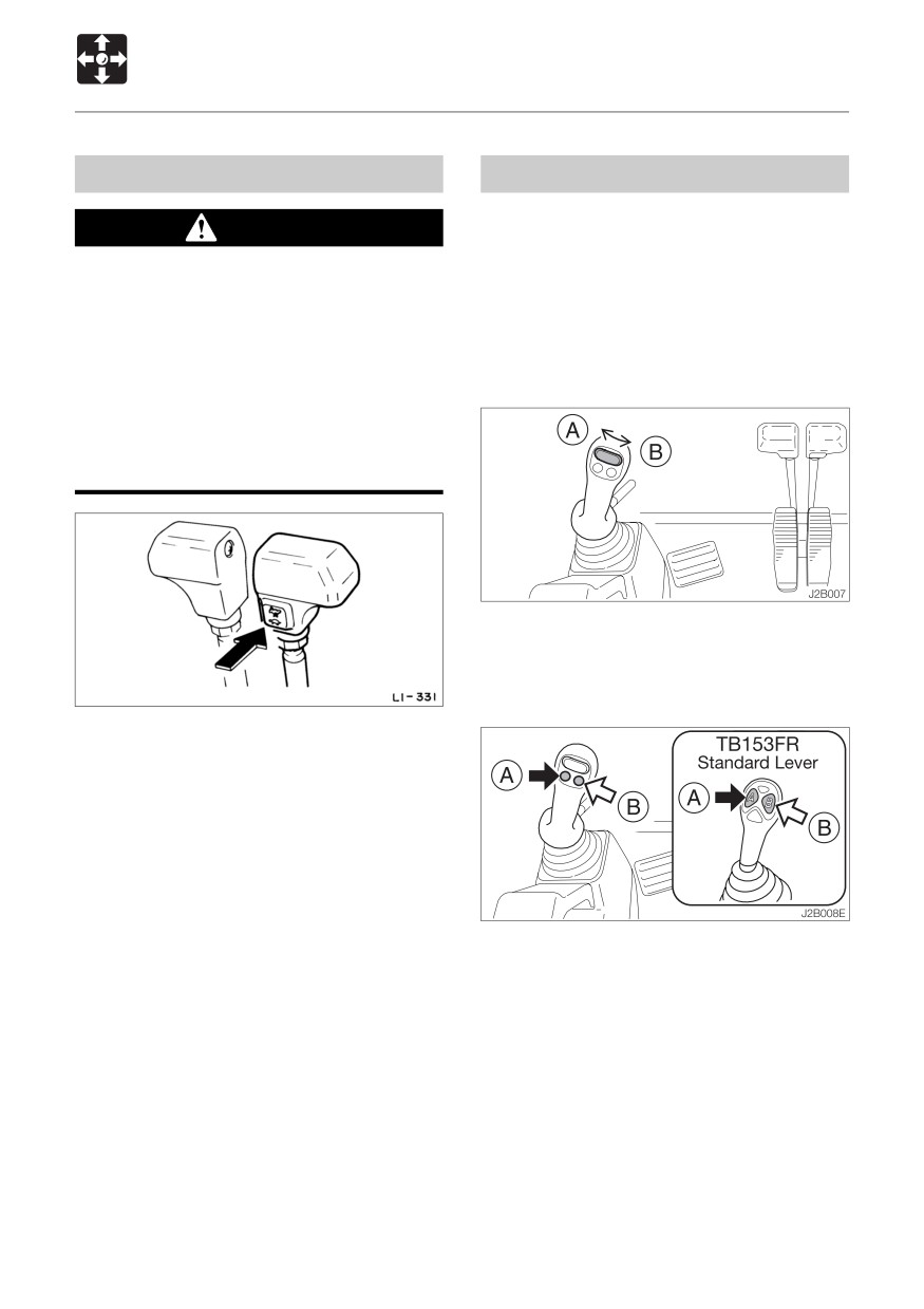
Travel Speed Switch
First Auxiliary Hydraulic Switches
Slider Switch
WARNING
(Proportional control)
When a load greater than a set value is
Proportional control allows for slow-to-fast
applied during 2nd speed (high speed)
movement of auxiliary functions.
travel, the speed will automatically slow
Example: If you move the slider switch half
down by switching to 1st speed (low
way, the auxiliary function will move at
speed). Thereafter, when the load
approximately one-half speed.
becomes lighter, the speed will increase
by returning to 2nd speed (high speed).
Exercise due caution since the travel
speed changes automatically.
Move this switch to control the flow of the oil
in the first auxiliary hydraulic lines.
Auxiliary Hydraulic Buttons
Press this switch to set the travel speed to
2nd speed (high speed). Press again to
return to 1st speed (low speed).
Press those buttons to control the flow of the
oil in the first auxiliary hydraulic lines.
¡Proportional control of the auxiliary
hydraulic circuit is not possible.
(A)
Hydraulic oil flows to left auxiliary
line(a)
(B)
Hydraulic oil flows to right auxiliary
line(b)
51
CONTROLS
Switches
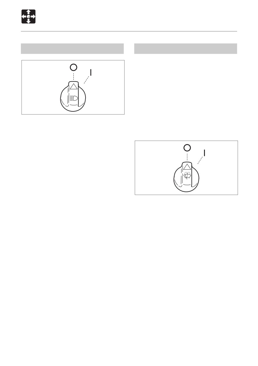
Light Switch
Wiper Switch (Cab)
IMPORTANT: If no washer fluid is
discharged, do not operate the washer.
Doing so may damage the pump.
IMPORTANT: Operating the wiper with no
moisture on the windshield will scratch
the glass. Apply water or washer fluid
when operating the wiper.
IMPORTANT: In cold seasons, the wiper
L3B028
blade may freeze to the glass. Operating
When this switch is turned while the starter
the wiper forcibly may damage the wiper
switch is at ON, the lights turn on as follows :
motor.
O
Off
I
Meter light, front light and boom light
turn on.
PUSH
L3B029
O
Off
I
Wiper operates.
PUSH
Washer fluid is squirted from the
nozzle while pressed, and stops
when released.
52
CONTROLS
Levers and Pedals
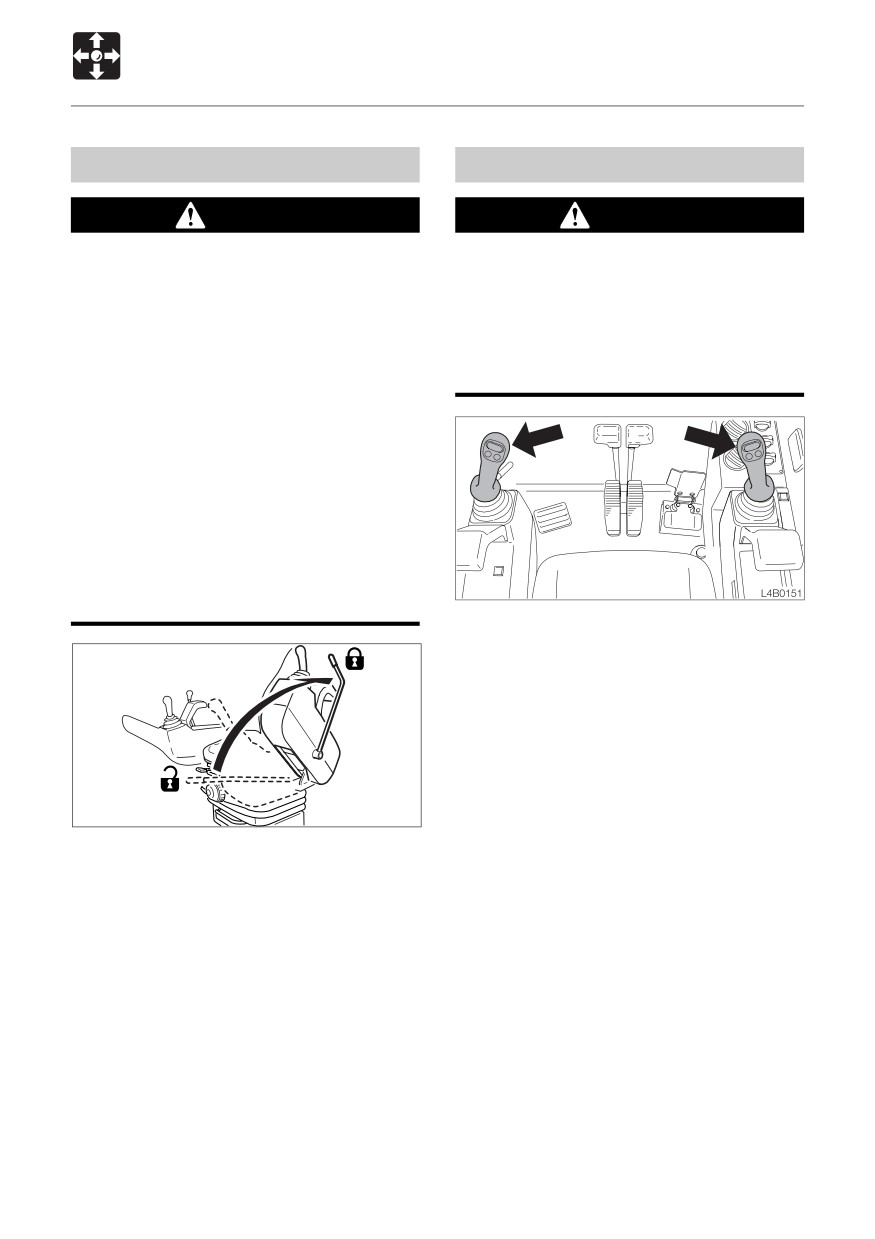
Safety Lock Lever
Operating Levers
WARNING
WARNING
¡Before leaving the operator’s seat,
¡ Be careful to check which pattern of
raise the safety lock lever to engage
lever control arrangement you are
the lock and stop the engine. If any
operating with before beginning
controls should be touched
operations.
accidentally when the safety lock lever
¡ The explanations in this manual are for
is lowered, the machine will move
the ISO pattern.
suddenly, and cause serious injury or
death.
¡ < TB153FR > : Note that the dozer blade
control is not locked, even when the
safety lock lever is set to the lock
position. Do not touch this control
accidentally.
¡ Be careful not to touch the operating
levers when raising and lowering the
safety lock lever.
Use these levers to operate the boom, arm,
bucket and upperstructure (slew).
Refer to page 74 “Lever Pattern”.
Refer to page 84 “Operating the Working
Equipment”.
S2B015
This device is for locking the working
equipment, auxiliary hydraulic control,
slewing and traveling.
When the lever is raised, the lever stand
springs up and the lever is locked.
¡ < TB153FR > : Note that the dozer blade
control is not locked, even when the safety
lock lever is set to the lock position. Do
not touch this control accidentally.
53
CONTROLS
Levers and Pedals
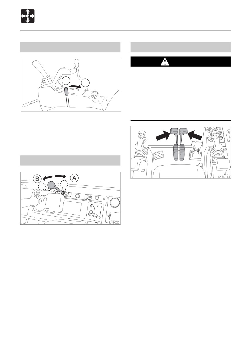
Throttle Lever < TB153FR >
Travel Levers
WARNING
Before operating the travel levers, check
A
to make sure that the dozer blade is to
B
the front of the operator’s seat. BE
AWARE that when the dozer blade is to
the rear of the operator’s seat, the travel
levers operate in the opposite direction
D5B021E
to when the dozer blade is in the front.
This controls the engine speed.
(A)
Low idling
(B)
Maximum speed
Blade Lever
Use these to move forward and backward
and to change directions.
Refer to page 79 “Operating the Travel
Levers”.
Use this lever to operate the dozer blade.
(A)
Blade up
(B)
Blade down
Refer to page 85 “Operating the Dozer
Blade”.
54
CONTROLS
Levers and Pedals
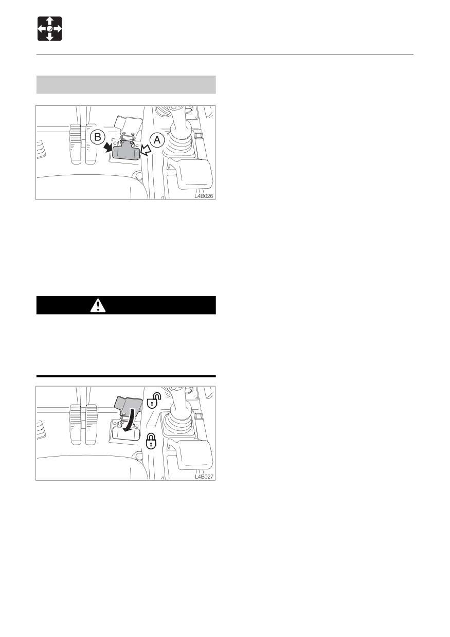
Offset Pedal
Use this pedal to operate the boom offset.
(A)
Boom offset right
(B)
Boom offset left
Refer to page 85 “Operating the Boom
Offset”.
Pedal Lock
WARNING
When not using the pedal, set the pedal
lock to the locked position. Stepping on
a pedal accidentally when it is not locked
may lead to unexpected accidents.
This device is for locking the offset pedal.
Set the pedal lock over the pedal to lock it.
55
CONTROLS
Accessories
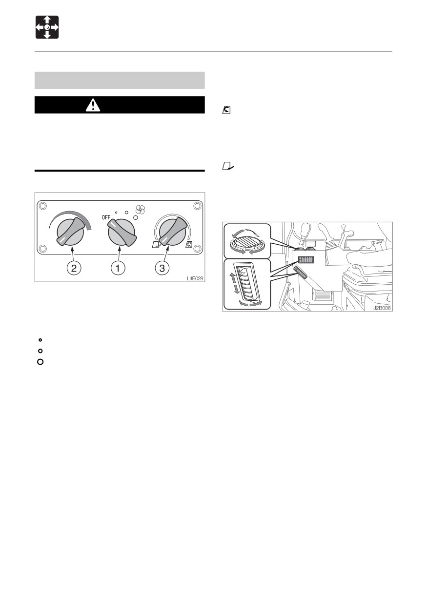
Airflow mode control dial (3)
Heater (Cab)
Use this dial to select recirculation or fresh
air intake.
WARNING
............... Recirculation
• To cool or heat the cab quickly
¡Always be sure to allow sufficient
• When external air is dirty
ventilation.
CENTER
50% fresh air intake
¡ Do not place combustible or explosive
• To ventilate while heating the cab slowly
objects near the air outlets.
............. Fresh air intake
• To remove fog from the windows
Control panel
• To ventilate while heating the cab
Outlets
Fan Switch (1)
Use this switch to adjust the fan speed in
three steps.
Move the louvers up and down or left and
OFF
Fan off
right to adjust the air flow direction and
............ Low
amount.
............ Medium
............ High
Supplement: Use the heater with care in
warm seasons. Coolant circulates in the
Temperature Control Dial (2)
heater even when the heater switch is turned
Use this dial to adjust the air temperature.
off.
Counterclockwise
When the heater is no longer needed, stop
.......................... To lower the temperature
coolant circulation as follows :
Clockwise
To increase the temperature
Supplement: No warm air is emitted if the
IMPORTANT: Use the valve (1) either fully
temperature of the engine coolant is low.
open or fully closed.
Cooling water could leak when the valve
is set at a halfway position.
56
CONTROLS
Accessories
< TB153FR >
Interior Light (Cab)
IMPORTANT: The battery capacity will
decrease if the interior light is left on for
long periods of time the engine stopped.
Turn the lamp off when leaving the
machine.
< TB180FR >
I
O
C4C024
O
Off
I
Lit
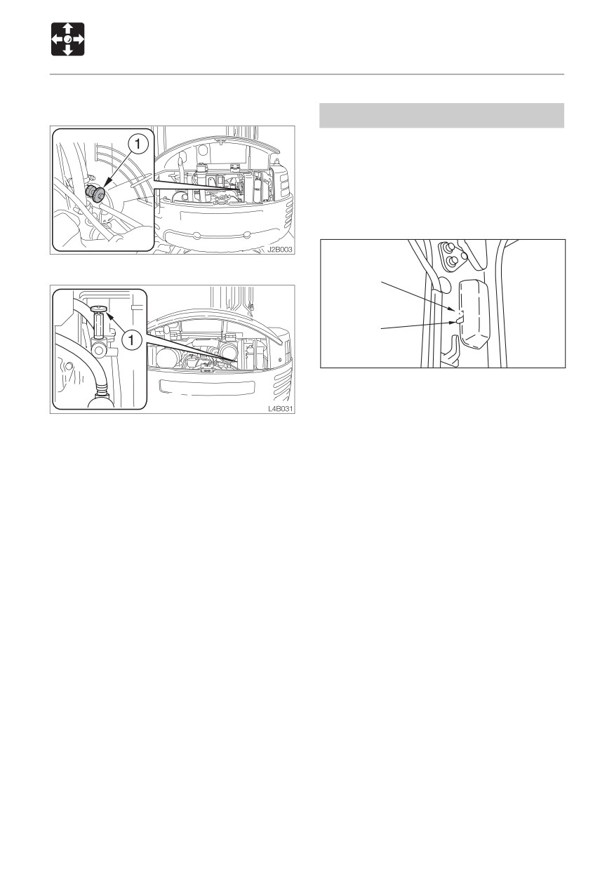
1. Park on a flat surface and stop the engine.
2. Open the engine hood.
3. Turn the valve (1) clockwise until it stops
to close it.
57
CONTROLS
Accessories
Cigarette Lighter (Cab)
Ashtray (Cab)
WARNING
WARNING
¡Do not leave the cigarette lighter’s
¡ Be sure to extinguish cigarettes and
knob pressed in. Doing so heats up the
matches completely before putting
lighter, and could be dangerous.
them in the ashtray, and always close
¡ If the knob does not pop out after 30
the ashtray afterwards.
seconds, it may be broken. Pull it out
¡Do not overfill the ashtray with
by hand.
cigarette butts or put in paper or other
¡ Do not use other cigarette lighters, as
easily burnable objects. Doing so could
they may get stuck.
lead to fire.
¡ Only use applicable electric products
with this socket.
¡ Do not touch metal parts of the lighter.
Doing so could cause burns.
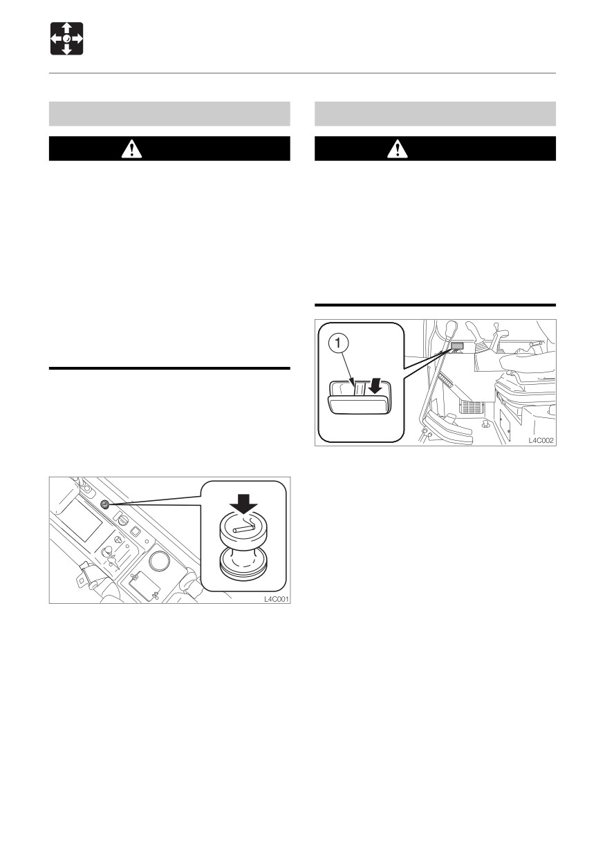
This is the cigarette lighter and internal power
supply socket.
When using the wiper and this socket
simultaneously, be careful not to exceed
12V / 10A.
Pull the ashtray out towards you to use it.
To clean, press the ash discharge button (1)
and pull out the ashtray.
1. Press the lighter in.
2. Release the lighter and wait for it to pop
out. The lighter pops out automatically
when the heater becomes red.
3. Once the lighter pops out, pull it out.
58
CONTROLS
Accessories
External Power Sockets (for EU)
WARNING
Only use applicable electric products with
these sockets.
1
L2C0071
for Beacon
1
N0C008
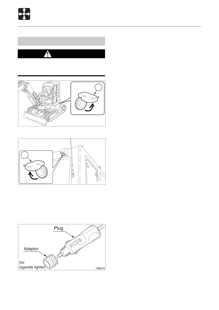
Use these sockets as an external power
supply. When using these sockets, be
careful not to exceed 12V / 10A.
To use, raise the cap (1).
Applicable plug: BOSCH 0352321007
59
CONTROLS
Accessories
Radio
Operating precautions
¡ To ensure safe operation of the machine, always be sure to keep the volume of the radio
down to a level where you can easily hear sounds from outside the machine.
¡ Do not keep the radio playing for long periods of time with the engine stopped. Doing so
will drain the battery of its charge and make it difficult or impossible to restart the engine.
¡ Be careful not to allow water or other liquids to come into contact with the radio . Doing so
may result in it being rendered inoperable.
¡ Be careful not to insert cassette tapes backward. Doing so may damage the cassette
player. Insert tapes with the head of the tape facing to the right.
¡ Always remove the cassette from the player when not in use.
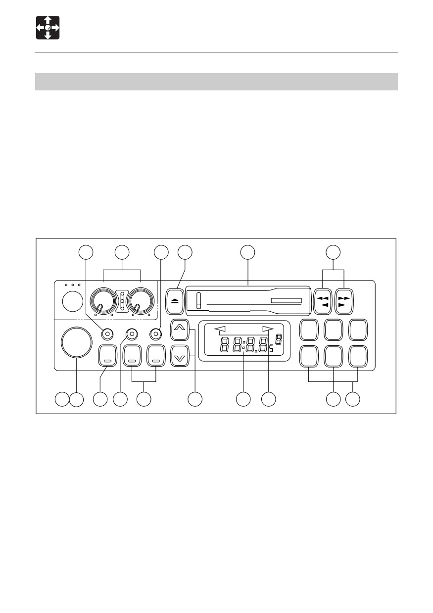
Names of components
16
3
15
6
7
8
BASS
TRE
KRH-M867
DC12V/24V
AUTO REVERSE CASSETTE STEREO RECEIVER
PS/AS
LOUD
DISP
VOL
MTL LOUD ST
1
2
3
M
FM1
FM2
SEEK
SEEK
H
AM
BAND
DN
UP
4
5
6
METAL
1
2
12
11
10
9
5
4
13
14
L2C001
(1) (2) Power switch / volume control knob
(3) Tone control
Turn this knob clockwise. The “click” sound
¡ Bass control knob
indicates that the power supply is turned on.
¡ Treble control knob
Further turning increases the speaker
volume. If a tape is loaded in the radio, eject
the tape to switch to the radio.
60
CONTROLS
Accessories
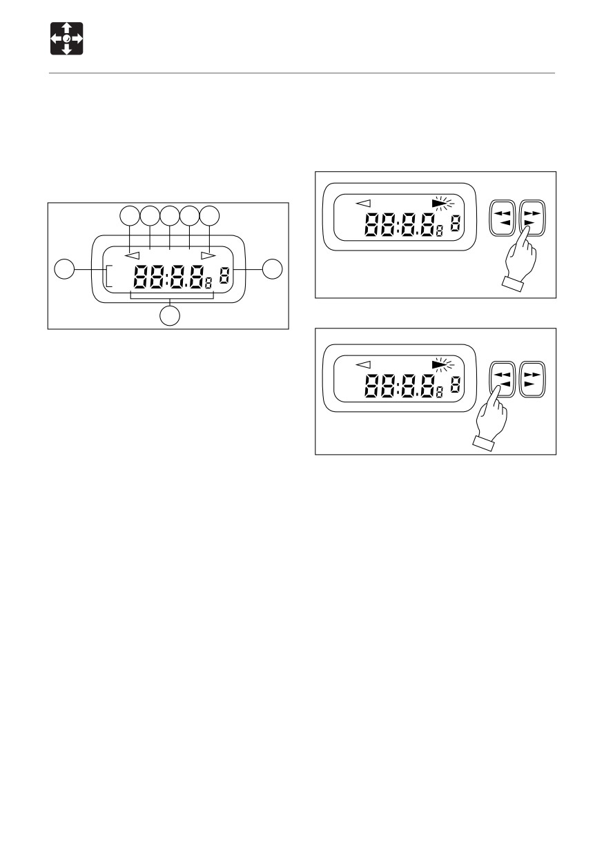
(4) Program indicators
(8) Fast-forward / rewind /
Indicates tape direction. When s lamp is on.
program changeover button
Upper side of a tape is playback, t indicates
playback of lower side.
Fast-forward
(5) Display
MTL LOUD ST
G
D F
E G
FM1
FM2
AM
MTL LOUD ST
A
FM1
C
FM2
AM
L2C003
Fast-rewind / Stop
B
L2C002
(A) Band
(B) Time / Frequency
MTL LOUD ST
(C) Memory channel (1-6)
FM1
FM2
(D) Metal
AM
(E) FM Stereo
(F) Loudness
(G) Tape direction
L2C004
(6) Eject button
To fast-forward the tape, push the button
Push this button to eject the cassette tape.
matching the direction of program indication
¡ To change over to radio while listening to
and to rewind, push the other button. To stop
a cassette tape, press the EJECT button
fast-forwarding or rewinding, lightly press the
to stop the tape and the system will
button which is not locked to cancel the
automatically change over to radio.
operation. The system will then start playing
the tape again normally.
(7) Cassette door
Insert the cassette tape with the exposed
magnetic tape side facing to the right.
¡ Simply insert a tape to change over to the
cassette tape mode while listening to the
radio.
61
CONTROLS
Accessories
(12) Band select switch
KRH-M867
Pressing the “BAND” button changes over
DC12V/24V
AUTO REVERSE CASSETTE STEREO RECEIVER
between FM1, FM2 and AM (MW) bands.
The display indicates the receiving band
MTL LOUD ST
1
2
3
M
name and frequency.
FM1
FM2
H
AM
4
5
6
METAL
(13) Metal switch
Press the “MTL” (5) button before playing a
L2C005
metal or CrO2 tape.
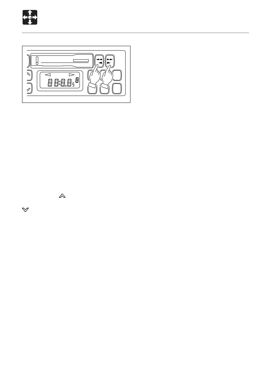
To change the program, press the fast-
The “MTL” indication appears on the display.
forward and rewind buttons simultaneously.
The direction of tape feed will reverse.
(14) Preset switch keys
One station each in the FM1, FM2 and
¡ When the tape ends in one direction, the
AM(MW) bands, respectively, can be preset
system automatically reverses the tape
for each of these preset keys.
and plays the other side.
When listening to a preset station, select
¡ To stop fast-forwarding or rewinding, lightly
either of the AM, FM1,FM2 bands using the
touch the unlocked key. This frees the
band select switch, then simply press the
locked key and normal playing resumes.
number key corresponding to the preset
selected station.
(9) Tuner switch (Manual tuning)
The system can memorize 6 stations in AM
Pressing the
shaped TUNER button
band and 12 stations in FM bands (FM1: 6
raises the receiving frequency. Pressing the
stations and FM2: 6 stations).
shaped TUNER button lowers the
receiving frequency similarly. Pressing either
Manual Memory
of these buttons continuously shifts the
Use manual tuning button or seek tuning
receiving frequency continuously.
button to choose a radio station if a
broadcasting station is wanted to be
(10) SEEK switch
recorded. For 2 seconds press 1-6 preset
Pressing the “SEEK” button shifts the
key when the indication of frequency has
receiving frequency in the higher or lower
already shown and the frequency is
frequency direction before automatically
recorded. Flash stops and channel starts
stopping at a position where a station is
functioning.
picked up.
¡ If the main power supply is interrupted,
(11) LOUD switch
such as when exchanging machine
This button is used to operate the system at
battery, all presettings will be erased.
a lower sound volume but with enhanced
Repeat the presetting procedure in
bass and treble sound. (“LOUD” indication
such case.
appears on the display.)
62

CONTROLS
Accessories
(15) DISP (Time / Frequency) button
¡ Set the time
This system is equipped with a clock which
TRE
TRE
can show the accurate time. Even if the radio
is off, the clock still shows the time.
AS
LOUD
DISP
LOUD
DISP
(16) PS / AS switch
M
M
Push this button
2 sec below will
SEEK
SEEK
H
SEEK
SEEK
H
automatically operates to show the
ND
DN
UP
DN
UP
memorized station from 1 to 6. The signal
L2C006
scaning start by pushing this button
momentarily. When a station is received the
After pressing DISP button, press tuner
scaning automatically stops there for 5
button
or
to correct the time. Press
seconds FLASHLY and then resumes
tuner button
to set the “hour” and tuner
scaning. As soon as the desired station is
button
for setting the “minute”. Set the
found, press the this button again.
time when the time is shown.
If you will auto memory push this button over
5 sec so initiates a scan of the band. Station
frequencies are either stored in order of low
of frequency for FM, or in sequence for AM,
starting from preset channel 1. If all of the
preset channels have not been filled up after
one scan, the remaining preset channels are
left unchanged, and channel 1 is recalled.
Channel 8 flashes during A.
63

CONTROLS
Accessories
2. Remove the plugs.
First Auxiliary Hydraulic Lines
3. Connect the attachment hydraulic lines to
ports (a) and (b).
WARNING
When fitted with a hydraulic breaker,
connect the return circuit to port (b) and
Oil may spurt out if caps or filters are
the supply circuit to port (a).
removed or pipes disconnected before
4. Open the stop valves.
releasing the pressure in the hydraulic
When fitted with a hydraulic breaker, open
system.
the selector valve (1).
¡ When disconnecting hoses, release the
Refer to pege 65 “Selector valve”.
internal pressure before removing.
5. When connecting is complete, purge air
from the hydraulic lines.
These lines deliver the hydraulic oil
a. Start and run the engine at low idle with
necessary for operating a hydraulic breaker,
no load for 10 minutes.
crusher or other attachments.
b. With the engine running at low idle
operate the auxiliary hydraulic switches
< TB153FR >
repeatedly (approx. 10 times) to purge
air from the hydraulic lines.
S
O
c. Stop the engine and wait for more than
5 minutes until bubbles escape from the
hydraulic oil in the tank.
b
IMPORTANT: Follow the procedures for
a
purging air as instructed by the
J1C002
attachment manufacturer if specified to
do so.
< TB180FR >
6. Check for leaks.
Disconnecting the hydraulic circuits
1. Release the pressure remaining in the
lines then close the stop valve.
Refer to “Releasing the residual pressure”.
2. Disconnect the lines from ports (a) and
(b).
3. Install the plugs.
Stop valve
S : Closed O : Open
Releasing the residual pressure
Connecting the Hydraulic Circuits
After using the auxilliary hydraulic circuits,
To connect the attachment hydraulic lines,
pressure remains in the circuits. This is called
use the following procedures:
the residual pressure. Release this residual
1. Release the pressure remaining in the
pressure before disconnecting the lines.
lines then close the stop valve.
Refer to “Releasing the residual pressure”.
64
CONTROLS
Accessories
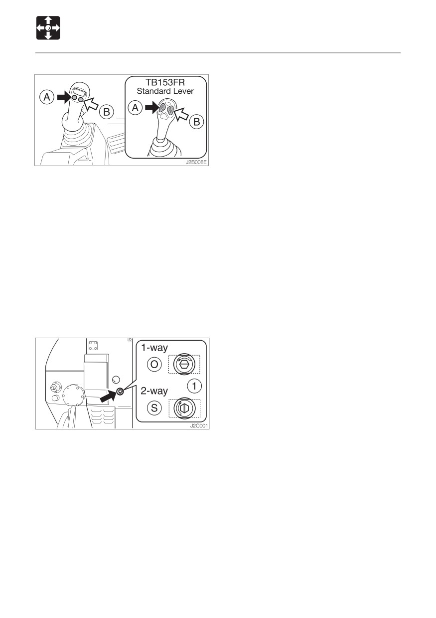
1. Start the engine and press the auxiliary
hydraulic button (B).
(The residual pressure is released from
the (a) port line, and pressure is generated
in the (b) port.)
2. Stop the engine and open the selector
valve (1) on the machine body.
(The residual pressure is released from
the (b) port line.)
When equipped with accumulator (option) :
Refer to page 204 “Releasing the residual
pressure”.
Selector valve
O: Open
When using a hydraulic
breaker (1-way flow)
S: Closed
When using a reversible
attachment (2-way flow)
Change the direction of the hydraulic oil flow
by opening or closing the selector valve on
the machine body.
65
66
OPERATION
Before Starting Operation
68
Starting and Stopping the Engine
<TB153FR>
70
Starting and Stopping the Engine
<TB180FR>
72
Machine Operation
74
Operating Procedures
88
Parking the Machine
96
Handling in Cold Weather
97
Handling Rubber Crawlers
98
67
OPERATION
Before Starting Operation
Mounting and Dismounting
Walk-Around Inspection
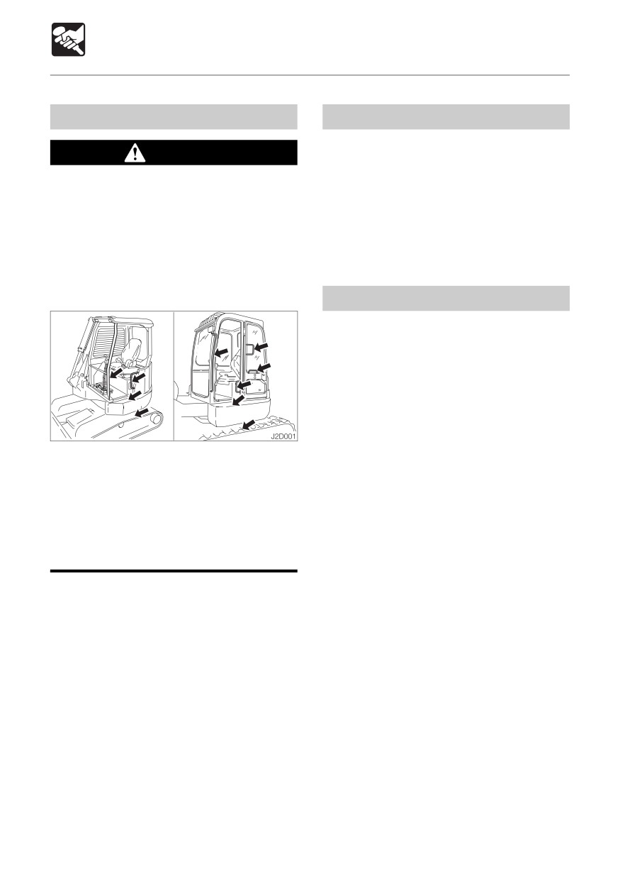
Perform the walk-around inspections once
WARNING
a day before starting the engine the first time
¡ Do not jump on or off the machine.
that day.
Never attempt to mount or dismount a
Perform the inspections as described under
moving machine.
“Maintenance - Walk-Around Inspection”
¡ When mounting and dismounting the
(pages 118 and 119).
cab, first open the door fully to the
locked position and check that it does
not move. (For machines with cabs)
Daily Inspection
Perform the daily inspections once a day
before starting the engine the first time that
day.
Perform the inspections as described under
“Maintenance - Daily Inspection” (pages
120 to 124).
¡ Always face the access system and
maintain a three point contact with the
recommended handrails and steps
while getting on and off the machine.
Keep steps and platform clean.
¡Never use the safety lock lever or
control levers as hand holds.
68
OPERATION
Before Starting Operation
Before Starting the Engine
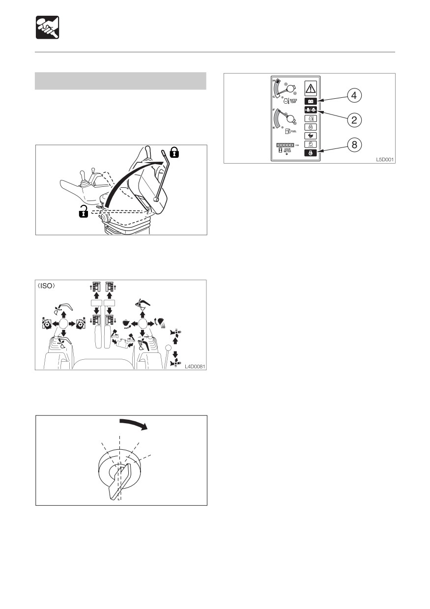
1. Adjust the seat for a comfortable operating
position.
2. Fasten the seat belt.
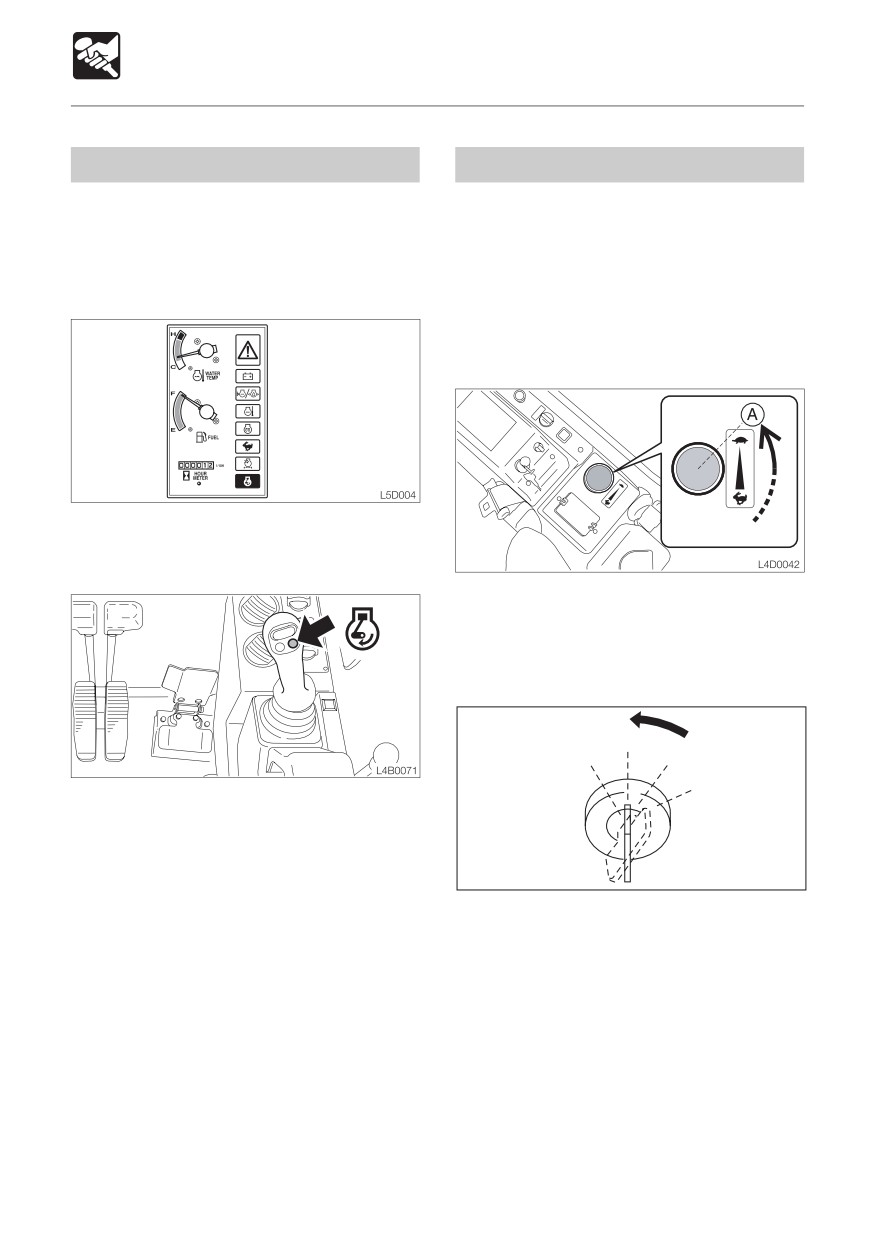
¡All the warning lamps flash and an
alarm is sounded for 2 seconds. The
meters also start functioning. After 2
seconds, only the battery charge
warning lamp (4) and engine oil
S2B015
pressure / coolant level warning lamp
(2) flash, and the other lamps turn off.
3. Check that the safety lock lever is in the
¡ < TB180FR > : Check that the decel. lamp
locked position.
(8) is lit.
¡ Turn the light switch to check that the
boom light, front light and meter light
turn on.
¡ Check the fuel level.
If a lamp does not light or the alarm is not
sounded, the bulb may be burnt out or a wire
may be damaged. Contact a Takeuchi sales
or service outlet for repairs.
4. Check that all the levers and pedals are
in the neutral position.
PREHEAT
OFF ON
START
E4D002
5. Insert the key into the starter switch, turn
it to the ON position, then perform the
following inspection :
69
OPERATION
Starting and Stopping the Engine < TB153FR >
Starting in Cold Weather
Starting the Engine
WARNING
¡ Clear the area of all persons.
¡ Sound horn to alert everyone around
the machine.
IMPORTANT: Do not run the starter motor
D5D014E
for more than 15 consecutive seconds. If
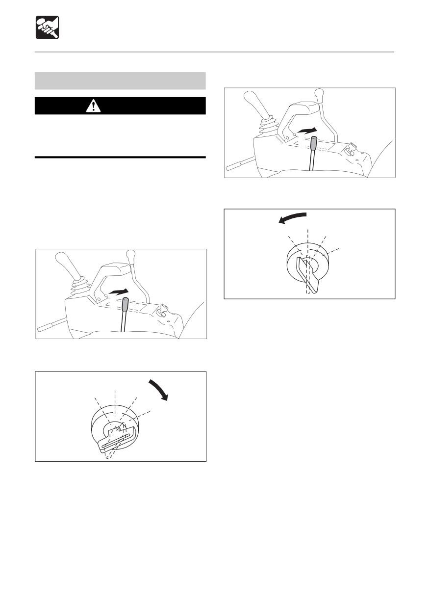
1. Pull the throttle lever to the middle position.
the engine fails to start, wait for 30
seconds to protect the battery, and then
try again to start the engine.
OFF
PREHEAT
ON
Normal Starting
START
E4D060
2. Turn the key to the PREHEAT position and
hold it there while the glow lamp is lit (about
D5D014E
15 seconds).
3. After the glow lamp turns off, then turn it
1. Pull the throttle lever to the middle position.
to the START position and start the engine.
4. Once the engine starts, release the key.
OFF
The key automatically returns to the ON
PREHEAT
ON
position.
5. Check that the warning lamps are off.
START
6. Return the throttle lever and warm up the
engine.
Refer to page 71 “Warming Up the
Engine”.
E4D005
2. Turn the key to the START position and
start the engine.
3. Once the engine starts, release the key.
The key automatically returns to the ON
position.
4. Check that the warning lamps are off.
5. Return the throttle lever and warm up the
engine.
Refer to page 71 “Warming Up the
Engine”.
70
OPERATION
Starting and Stopping the Engine < TB153FR >
Warming Up the Engine
Stopping the Engine
IMPORTANT: Avoid racing the engine IMPORTANT: Do not stop the engine
until it is warmed up.
suddenly when operating with heavy
Do not warm up the engine for long
loads or at maximum speed. Doing so
periods of time (20 minutes or more).
may cause the engine to overheat or
seize. Never bring the engine to a sudden
stop except in the case of a true
emergency.
D5D015E
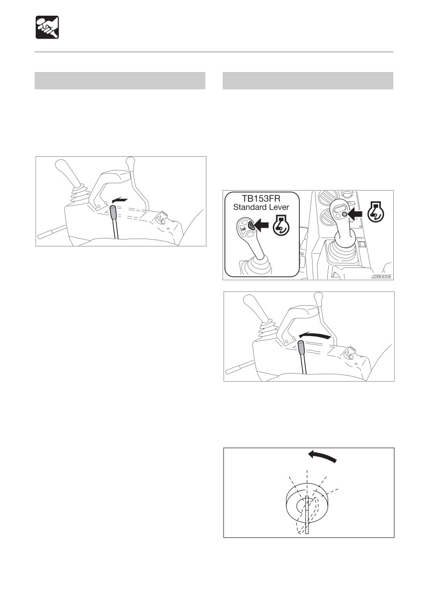
1. Return the throttle lever, then idle the
engine and run it for about 5 minutes with
no load.
D5D016E
1. Press the decel. button or return the
throttle lever.
2. Idle the engine for about 5 minutes to
gradually let it cool.
OFF
PREHEAT
ON
START
E4D007
3. Turn the key to the OFF position to stop
the engine.
71
OPERATION
Starting and Stopping the Engine < TB180FR >
Starting in Cold Weather
Starting the Engine
OFF
WARNING
PREHEAT
ON
¡ Clear the area of all persons.
START
¡ Sound horn to alert everyone around
the machine.
IMPORTANT: Do not run the starter motor
E4D060
for more than 15 consecutive seconds. If
the engine fails to start, wait for 30
seconds to protect the battery, and then
try again to start the engine.
Normal Starting
OFF
PREHEAT
ON
START
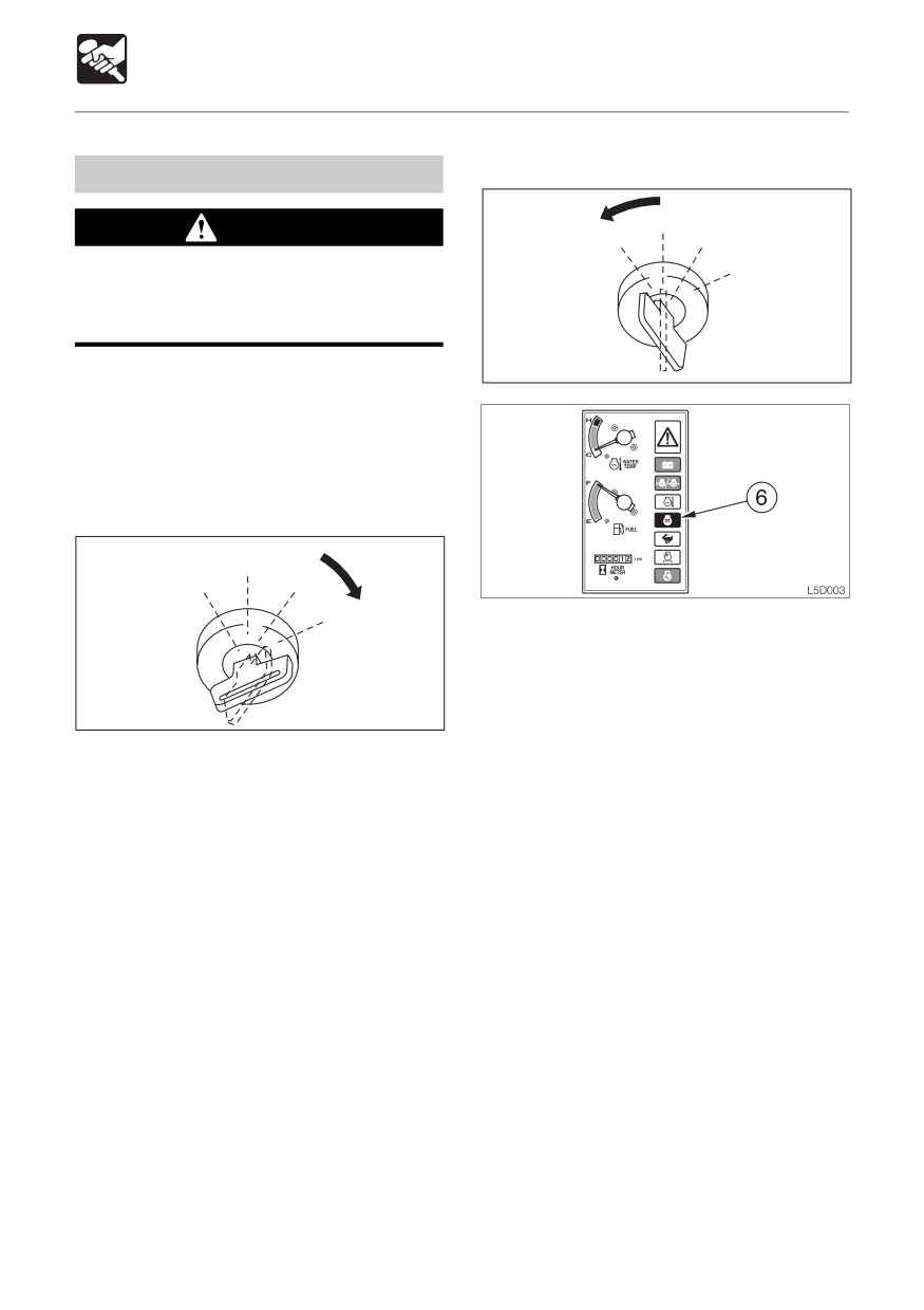
1. Turn the key to the PREHEAT position and
hold it there while the glow lamp (6) is lit
(about 15 seconds).
2. After the glow lamp (6) turns off, then turn
E4D005
it to the START position and start the
engine.
1. Turn the key to the START position and
3. Once the engine starts, release the key.
start the engine.
The key automatically returns to the ON
2. Once the engine starts, release the key.
position.
The key automatically returns to the ON
4. Check that the warning lamps are off.
position.
5. Warm up the engine :
3. Check that the warning lamps are off.
Refer to page 73 “Warming Up the
4. Warm up the engine :
Engine”.
Refer to page 73 “Warming Up the
Engine”.
72
OPERATION
Starting and Stopping the Engine < TB180FR >
Warming Up the Engine
Stopping the Engine
IMPORTANT: Avoid racing the engine IMPORTANT: Do not stop the engine
until it is warmed up.
suddenly when operating with heavy
Do not warm up the engine for long
loads or at maximum speed. Doing so
periods of time (20 minutes or more).
may cause the engine to overheat or
seize. Never bring the engine to a sudden
stop except in the case of a true
emergency.
1. Idle the engine and run it for about 5
minutes with no load.
1. Press the decel. button or return the
throttle controller.
2. Idle the engine for about 5 minutes to
gradually let it cool.
OFF
PREHEAT
ON
START
2. Press the decel. button to return to the
engine speed set with the throttle
controller.
E4D007
3. Turn the key to the OFF position to stop
the engine.
73
OPERATION
Machine Operation
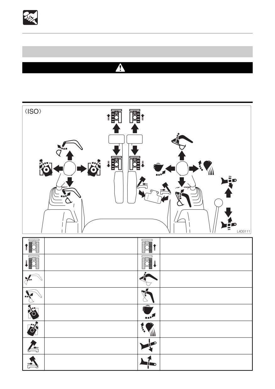
Lever Pattern (ISO Pattern)
WARNING
¡ Be careful to check which pattern of lever control arrangement you are operating
with before beginning operations.
¡ The explanations in this manual are for the ISO pattern.
Left Crawler Forward
Right Crawler Forward
Left Crawler Reverse
Right Crawler Reverse
Arm Out
Boom Lower
Arm In
Boom Raise
Upperstructure Left Slew
Bucket Load
Upperstructure Right Slew
Bucket Dump
Boom Offset Left
Dozer Blade Lower
Boom Offset Right
Dozer Blade Raise
74
OPERATION
Machine Operation
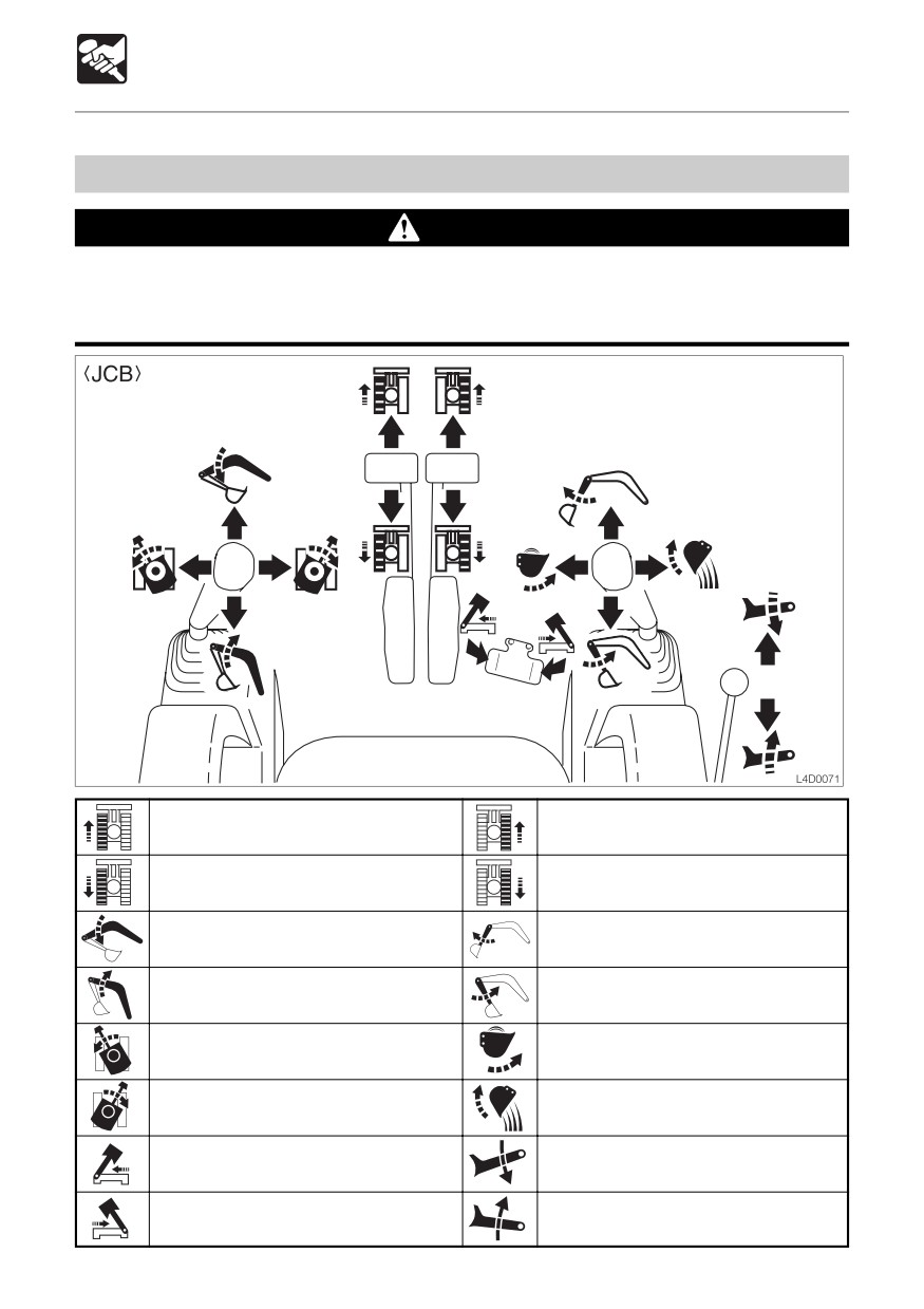
Lever Pattern (JCB Pattern)
WARNING
¡ Be careful to check which pattern of lever control arrangement you are operating
with before beginning operations.
¡ The explanations in this manual are for the ISO pattern.
Left Crawler Forward
Right Crawler Forward
Left Crawler Reverse
Right Crawler Reverse
Boom Lower
Arm Out
Boom Raise
Arm In
Upperstructure Left Slew
Bucket Load
Upperstructure Right Slew
Bucket Dump
Boom Offset Left
Dozer Blade Lower
Boom Offset Right
Dozer Blade Raise
75
OPERATION
Machine Operation
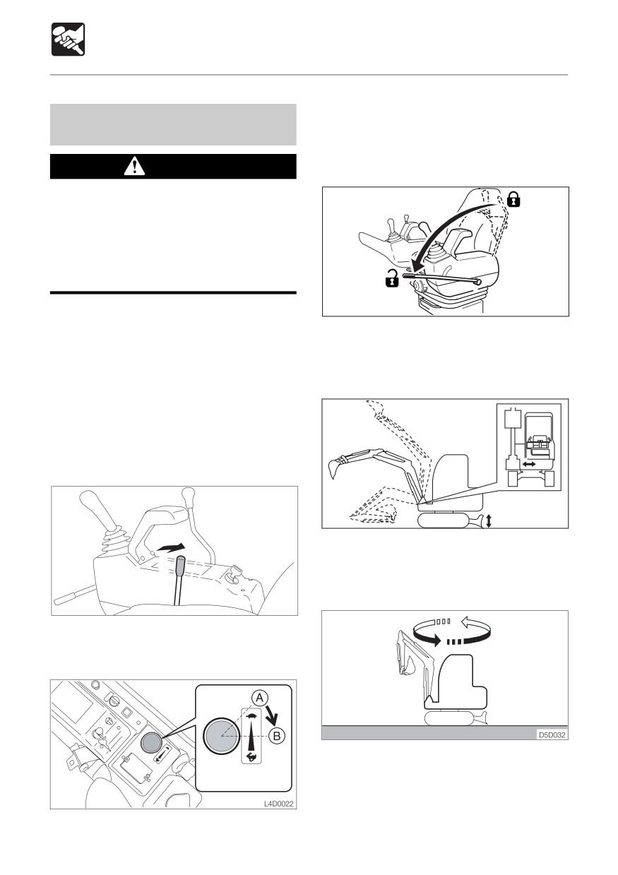
1. Turn the throttle controller to the middle
Warming Up the Machine
position (B).
(Hydraulic Oil)
2. Run the engine at medium speed for about
5 minutes with no load.
WARNING
Operating the working equipment without
warming up the machine (hydraulic oil)
is dangerous, as response will be slow
and the equipment may move in
unexpected ways. Be sure to sufficiently
warm up the machine.
IMPORTANT: Do not operate the levers
S2D007
suddenly when the hydraulic oil
3. Fully lower the safety lock lever to
temperature is below 20°C (68°F). The
disengage the lock and raise the pedal
proper hydraulic oil temperature during
lock to disengage the lock.
operation is 50 to 80°C (122 to 176°F), but
if operations must be performed at lower
temperatures, heat up the hydraulic oil
to at least 20°C (68°F).
Normal Warm-up
< TB153FR >
E4D009
4. Lift the bucket from the ground.
5. Extend and retract each of the cylinders
several times with no load.
D5D014E
1. Pull the throttle lever to the middle position.
< TB180FR >
6. Slew slowly left and right several times.
76
OPERATION
Machine Operation
Inspection After Warm-up
After warming up the engine and hydraulic
oil, perform the checks and inspections
described below, and repair if there is a
problem.
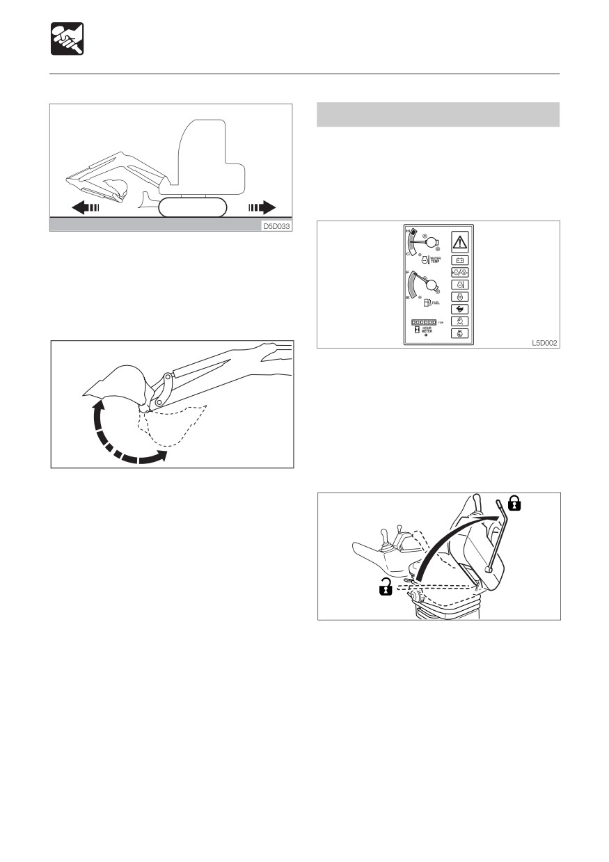
7. Travel slowly forward and backward
several times.
Warming Up in Cold Weather
1. Perform the normal warm-up procedure.
1. Check that the warning lamps and meters
are as follows :
• Are all the warning lamps off?
• Is the water temperature gauge’s needle
within the green range?
2. Check that there are no irregularities in
E4D011
the exhaust color, sound and vibrations.
2. Set the bucket cylinder at the stroke end
and keep it there.
Do not do this for more than 30 seconds.
3. Repeat step 2 until the bucket operating
speed is normal.
S2B015
3. Raise the safety lock lever to engage the
lock and check that the operating, offset,
dozer blade and travel levers are locked.
¡ < TB153FR >: Note that the dozer blade
control is not locked, even when the safety
lock lever is set to the lock position.
4. Perform the inspection operations
described below and check that the
bucket, arm and boom do not touch the
cab when the boom or bucket is moved
near the cab and stops automatically.
77
OPERATION
Machine Operation
1
L2D009
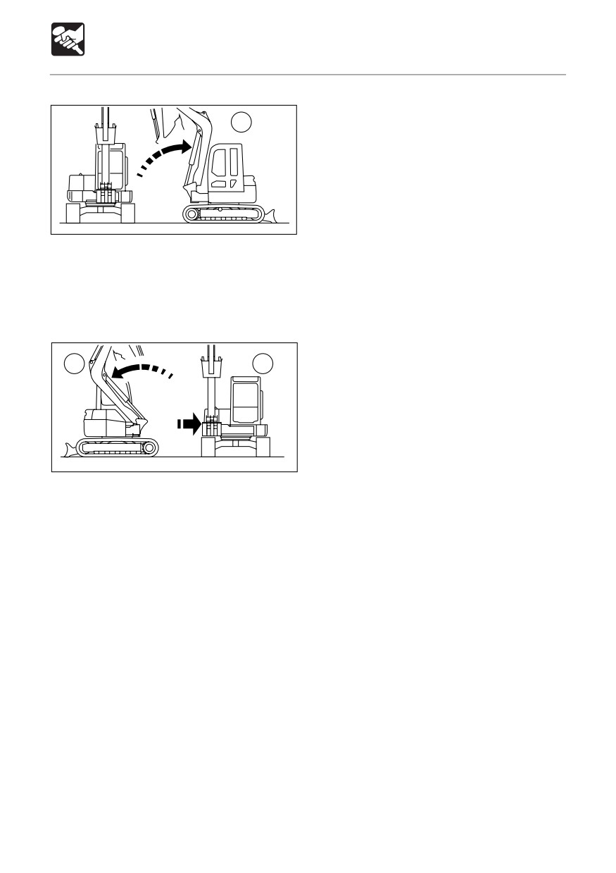
(1) Offset the boom to the front of the
operator’s seat and move the boom near
the cab.
Offset the boom to the right and move
the bucket near the cab.
2
3
L2D010
(2) Offset the boom fully to the right and
check that it can be set to the maximum
rear inclination.
(3) Offset to the left in the posture in (2)
above
Operation when the boom has stopped
automatically
1. If the boom has stopped while rising:
Operate the boom downward.
2. If the boom has stopped while offsetting
to the left:
a. Operate the boom downward to move
it outside the automatic stop range.
b. Offset to the left.
Offsetting to the right is possible
regardless of the boom’s posture.
78
OPERATION
Machine Operation
Traveling Forward and Backward
Operating the Travel Levers
1. Increase the engine speed.
WARNING
¡Never allow anyone to enter the
slewing (swing) radius and machine
path.
¡Signal your intention to move by
sounding the horn.
¡ There are blind spots to the rear of the
machine.
S2D007
If necessary,swing the cab around
2. Fully lower the safety lock lever to
before backing up to check that the
disengage the lock.
area is safe and clear.
30~40cm
E4D014
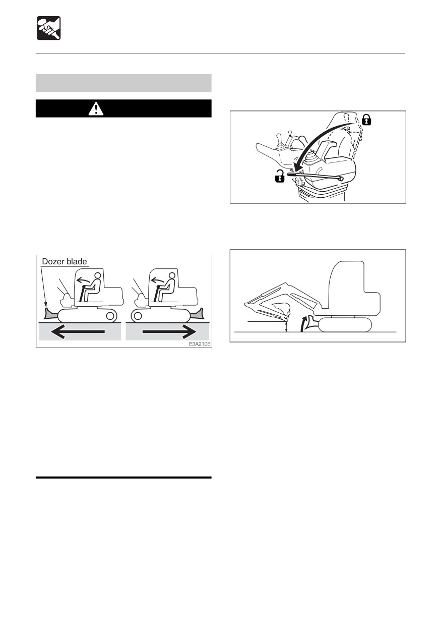
3. Fold the hoe attachment and lower it to
¡Before operating the travel levers,
30 to 40 cm(12 to 16 in.) above the ground.
check to make sure that the dozer blade
4. Lift the dozer blade.
is to the front of the operator’s seat.
5. Operate the left and right travel levers as
BE AWARE that when the dozer blade
described below.
is to the rear of the operator’s seat, the
travel levers operate in the opposite
direction to when the dozer blade is in
the front.
¡Remove any obstacles in the
machine’s path.
79