Takeuchi Mini Excavator TB260 (S/N 126000002~, S/N 126100003~). Operator's Manual - page 7
TROUBLESHOOTING
IF THE BATTERY GOES DEAD
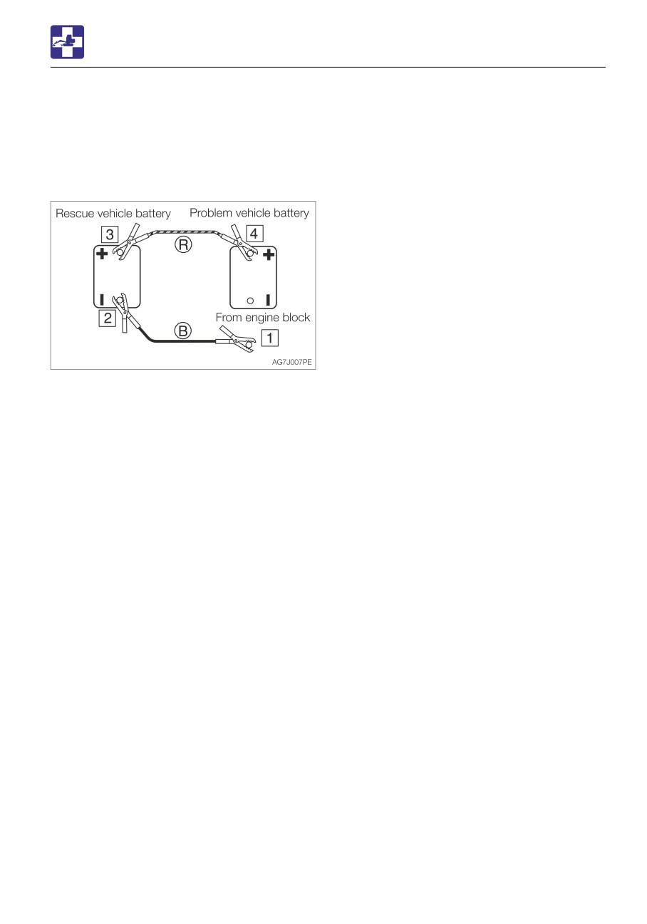
Disconnecting the jumper cables
Once the dead machine is successfully
running, remove the jumper cables by
following the same steps as for connection in
the reverse order.
1. Disconnect the clip of jumper cable (B)
from the engine block of the dead
machine.
2. Disconnect the other clip of jumper cable
(B) from the negative (-) battery terminal of
the booster vehicle.
3. Disconnect the clip of jumper cable (R)
from the positive (+) battery terminal of the
booster vehicle.
4. Disconnect the clip of jumper cable (R)
from the positive (+) battery terminal of the
dead machine.
Recharging
Ask your sales or service dealer for
recharging the dead battery.
6-5
TROUBLESHOOTING
IF A FUSE BLOWS
Fuse layout and circuits protected
IF A FUSE BLOWS
If a light does not come on or the electrical
Protected
system does not work, a fuse may be blown.
Capacity
Symbol
circuit
Inspect the fuses.
5A
Switch lighting
INSPECTING AND REPLACING THE FUSE
10A
Horn
5A
Starter switch
If the fuse blows again soon after
10A
Immobilizer
replacement, then the electric system is
likely faulty. It may pose a fire hazard if
not properly repaired. Contact your sales
25A
Light
or service dealer for advice.
10A*
Wiper
1. Turn the starter key to the OFF position to
20A*/15A
Lever lock
stop the engine.
Controller
15A
power supply
OX controller
20A
power supply
Cab interior
25A*
power supply
25A
Option (1)
10A*
Air conditioner
Engine ACC
<Applicable
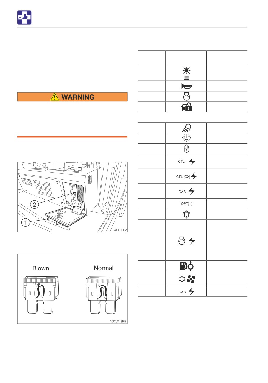
2. Open the fuse box cover (1).
machine
30A*
3. Check for any blown fuses (2).
models
126000002 or
later>
10A
Feed pump
Air conditioner
30A*
blower motor
25A
Cab light
*:
Cab
4. If a fuse is blown, replace it with a spare
fuse of the same capacity.
6-6
TROUBLESHOOTING
IF A FUSE BLOWS
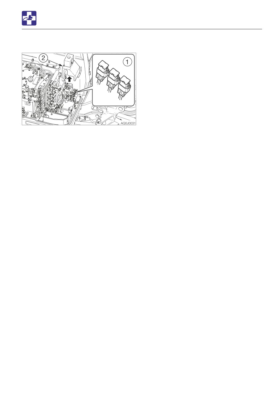
INSPECTING THE FUSIBLE LINK
If the machine is not turned on after turning
the starter switch to the ON position, there is
likely a break in the cartridge type fusible link
(1).
1. Open the right side cover.
2. Loosen the bolts and remove the cover
(2).
3. Inspect the fusible link (1).
4. If there is a break, please contact your
sales or service dealer.
Note: Fusible links are large type fuses used
in high current applications. Like a regular
fuse, they act as fuses by protecting the
electric components and wirings from
damage caused by excessive current draw.
6-7
TROUBLESHOOTING
RESTARTING AFTER ADDING FUEL
problems. Always bleed air when the fuel
RESTARTING AFTER ADDING
tank is emptied or when there is air in the
fuel system.
FUEL
BLEEDING AIR FROM THE FUEL SYSTEM
IMPORTANT: NEVER use the starter
motor to crank the engine in order to
prime the fuel system. This may cause the
starter motor to overheat and damage the
coils, pinion gear and/or ring gear.
IMPORTANT: If the engine stalls due to
fuel shortage, add fuel, turn the key to the
ON position for 60 seconds, and then turn
it to the START position. Running the
starter for a long time before there is
enough fuel is going through can cause
the starter to fail.
1. Add fuel.
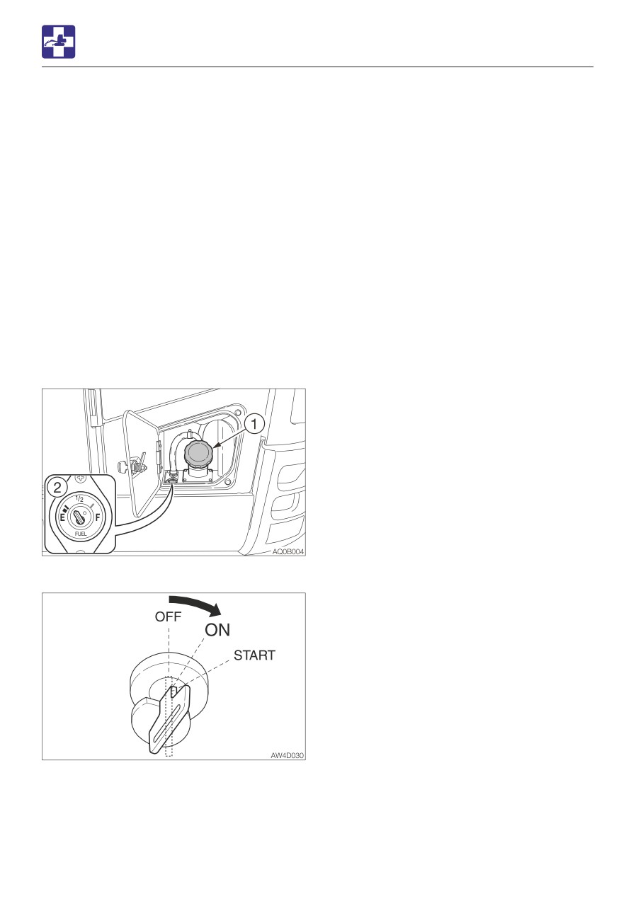
2. Turn the starter key to the ON position and
hold it for about 60 seconds.
The automatic air bleeder bleeds air from
the fuel system.
Note: Air in the fuel system causes the
engine to fail to start or to have other
6-8
MEMO
6-9
TROUBLESHOOTING
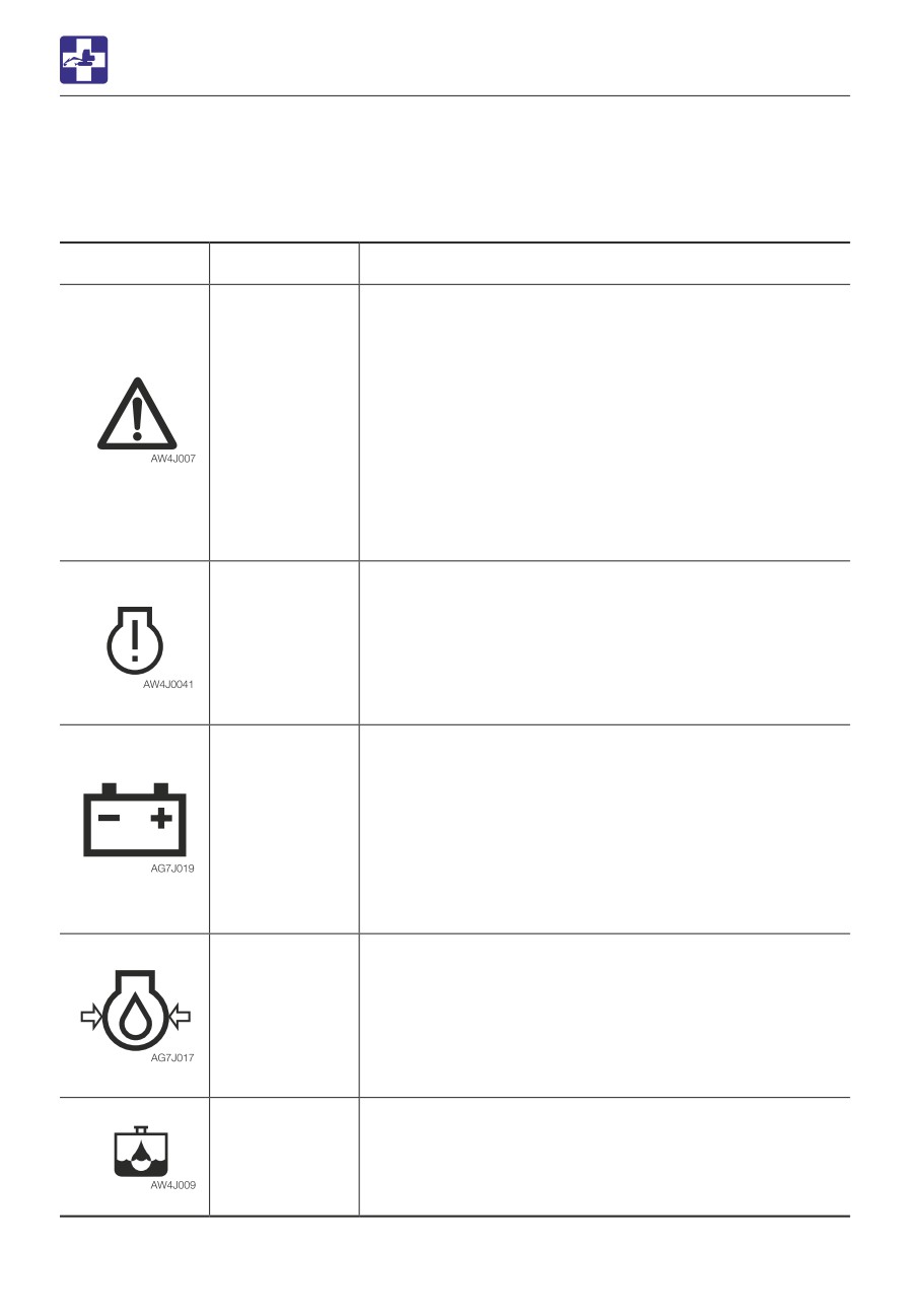
IF A WARNING LAMP FLASHES
IF A WARNING LAMP FLASHES
If an alarm is sounded or a warning lamp starts flashing during operation, park the machine in
a safe place and perform the remedy procedures described below.
Warning lamp
Lamp name
Causes and remedies
Vehicle and
There is a problem in the machine.
engine
Refer to the respective warning lamp below.
emergency
Get the vehicle or engine error code number from the
lamp
multi-information display or the instrument cluster, and
then consult your sales or service dealer referring to the
“Vehicle error code list” or “Engine error code list”.
Refer to “Multi-information display” on page 2-16 or
“Instrument cluster” on page 2-28.
Refer to “Vehicle error code list” on pages 6-12 and
6-13.
Refer to “Engine error code list” on pages 6-14 to 6-21.
<Applicable machine models 126100003 or later>
ECM error
An engine problem is detected.
warning lamp
If an error code is displayed on the multi-information
<Applicable
display or the instrument cluster, inform your sales or
machine
service dealer of the code and ask for help.
models
Refer to “Multi-information display” on page 2-16 or
126100003 or
“Instrument cluster” on page 2-28.
later>
Refer to “Engine error code list” on pages 6-14 to 6-21.
Battery charge
There is a problem with the fan belt or charger.
warning lamp
Check the fan belt for slack or breakage and adjust as
necessary.
If the lamp continues flashing after maintenance, there is
likely a problem with the charger. Consult your sales or
service dealer for help.
Refer to “Inspecting and adjusting the fan belt” on page
5-26.
Engine oil
There is a problem in the engine lubrication system.
pressure
warning lamp
Check the engine oil level. If the lamp is flashing when
the level is normal or even after replenishment of oil or
coolant, consult your sales or service dealer.
Refer to “Inspecting and replenishing the engine oil” on
page 5-19.
Water
Water is in the water separator. Drain water.
separator
Refer to “Draining the water from the water separator” on
warning lamp
page 5-61.
6-10
TROUBLESHOOTING
IF A WARNING LAMP FLASHES
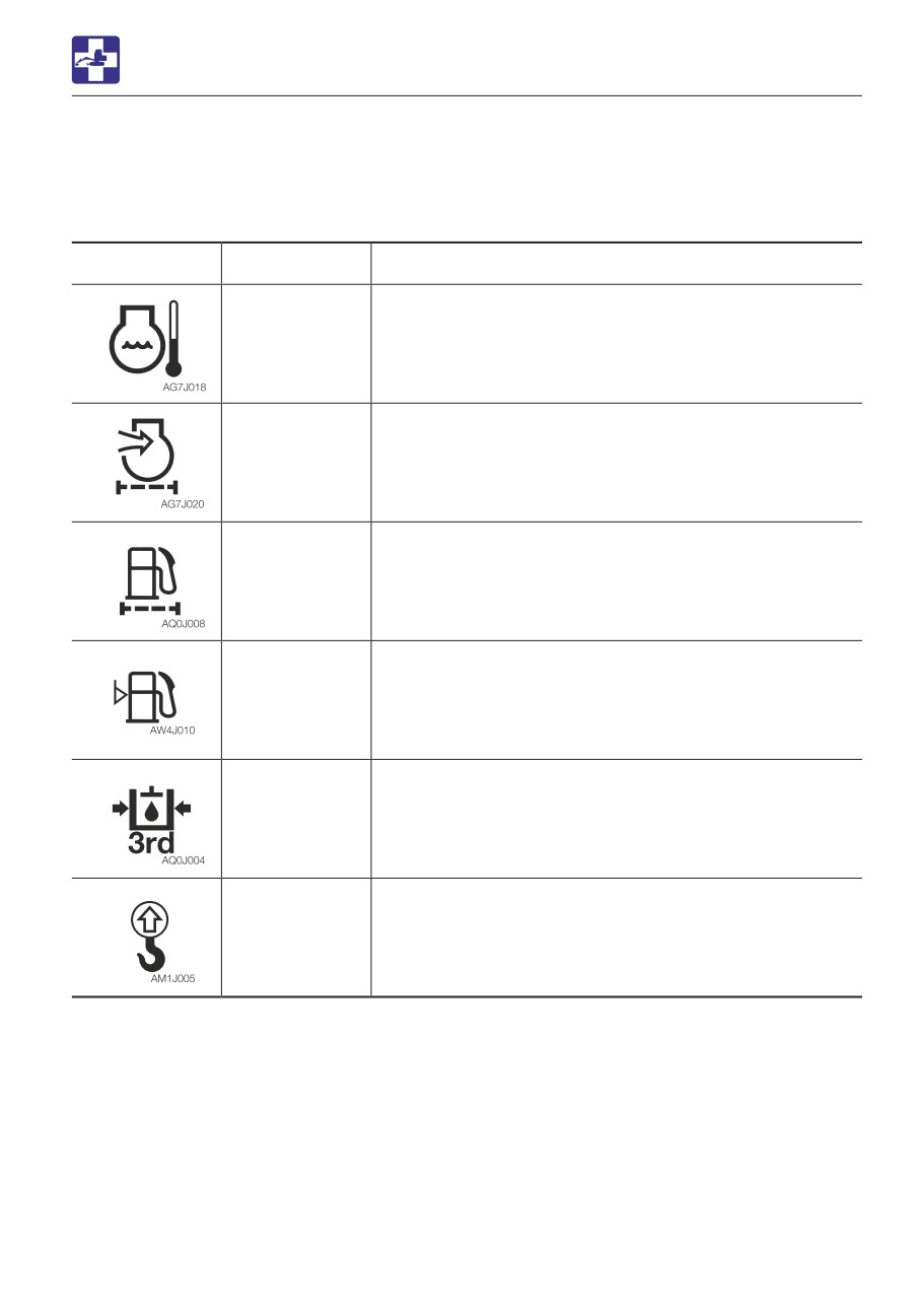
Warning lamp
Lamp name
Causes and remedies
Coolant
The coolant temperature is too high and the engine is
temperature
overheating.
warning lamp
Refer to “If the engine overheats” on page 6-3.
Air cleaner
The air cleaner is clogged. Clean it.
warning lamp
Refer to “Cleaning the air cleaner” on page 5-38.
Fuel filter
The fuel filter is clogged. Replace the fuel filter.
warning lamp
Refer to “Replacing the fuel filter” on page 5-44.
Fuel level
The fuel level is too low. Add fuel.
warning lamp
Refer to “Inspecting the fuel level” on page 5-21.
Third auxiliary
Pressure in the third auxiliary hydraulic line is too low
hydraulic
warning lamp
Consult your sales or service dealer for help.
Lift overload
This lamp starts flashing if the overload warning device is
warning
activated. If it occurs, reduce the load to be lifted.
indicator lamp
Refer to “Lift overload warning switch (If equipped)” on
page 2-57.
6-11
TROUBLESHOOTING
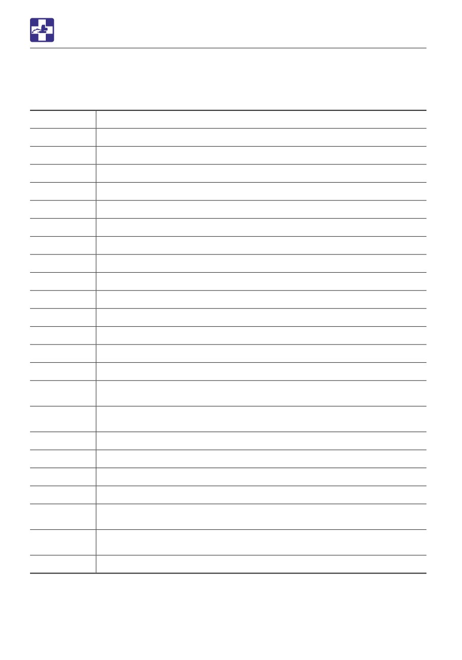
VEHICLE ERROR CODE LIST
VEHICLE ERROR CODE LIST
If an error code appears on the display, consult your sales or service dealer.
Error code
Error details
9
Impossible to sense ACC key
19
Parameter version mismatching
402
CAN 0 communication error
602
CAN communication error (cluster gauge)
612
CAN communication error (OX024)
1703
Main power supply voltage error (too high)
1704
Main power supply voltage error (too low)
1713
OX024 power supply voltage error (too high)
1714
OX024 power supply voltage error (too low)
2503
Sensor voltage error (too high) MMC
2504
Sensor voltage error (too low) MMC
3300
Alternator charge faulty
3401
Engine oil pressure error
3500
Overheat
Water temperature (high pressure) <Applicable machine models: 126000002
3503
or later>
Water temperature (low pressure) <Applicable machine models: 126000002
3504
or later>
3600
Air cleaner clogged
3700
Water separator alarm
5303
Accelerator sensor error (too high)
5304
Accelerator sensor error (too low)
Governor position sensor error (high pressure) <Applicable machine models:
5353
126000002 or later>
Governor position sensor error (low pressure) <Applicable machine models:
5354
126000002 or later>
5505
Fuel gauge resistance value error (cable break)
6-12
TROUBLESHOOTING
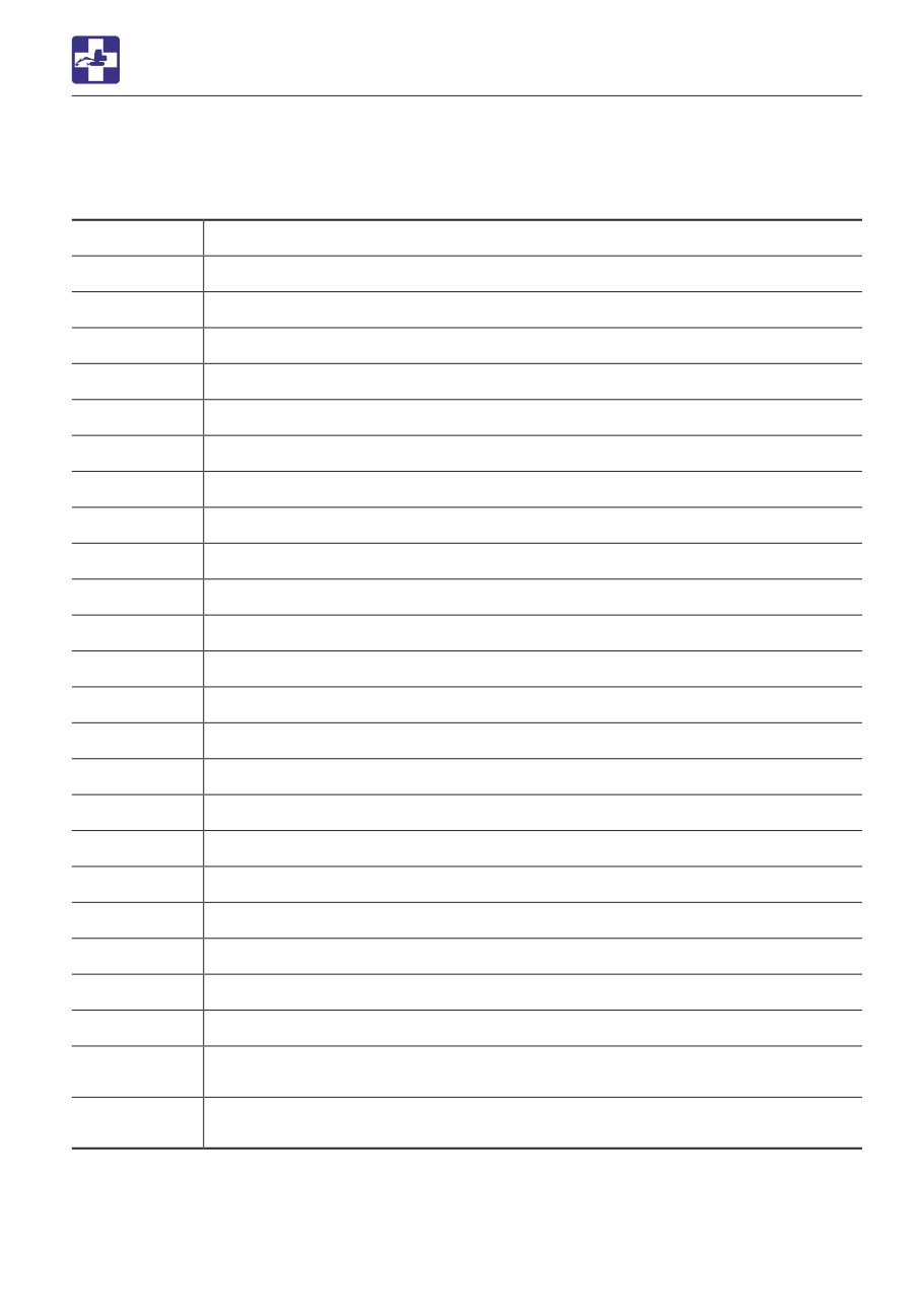
VEHICLE ERROR CODE LIST
Error code
Error details
5603
Lift alarm sensor error (too high)
5604
Lift alarm sensor error (too low)
6503
AUX1 slide switch voltage value error (too high)
6504
AUX1 slide switch voltage value error (too low)
6509
AUX1 slide switch neutral error
6519
AUX1 (L) switch error
6529
AUX1 (R) switch error
6603
AUX2 slide switch voltage value error (too high)
6604
AUX2 slide switch voltage value error (too low)
6609
AUX2 slide switch neutral error
6709
AUX3 button error (Grip)
6719
AUX3 switch error (Foot)
8005
Pump PWM output voltage error (too low)
8006
Pump PWM output voltage error (too high)
8015
AUX1 (L) PWM output voltage error (too low)
8016
AUX1 (L) PWM output voltage error (too high)
8025
AUX1 (R) PWM output voltage error (too low)
8026
AUX1 (R) PWM output voltage error (too high)
8035
AUX2 (L) PWM output voltage error (too low)
8036
AUX2 (L) PWM output voltage error (too high)
8045
AUX2 (R) PWM output voltage error (too low)
8046
AUX2 (R) PWM output voltage error (too high)
Throttle motor A (low pressure) <Applicable machine model: 126000002 or
8054
later>
Throttle motor B (low pressure) <Applicable machine model: 126000002 or
8064
later>
PWM = Pulse width modulation
6-13
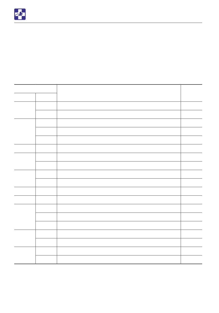
TROUBLESHOOTING
ENGINE ERROR CODE LIST
ENGINE ERROR CODE LIST
If an error code appears on the display, consult your sales or service dealer.
<Applicable machine models 126000002 or later>
No engine error code
<Applicable machine models 126100003 or later>
Error code
Error details
DTC
SPN
FMI
2
Crank speed sensor (Crank signal malfunction)
P0336
522400
5
Crank speed sensor (No crank signal)
P0337
2
Cam speed sensor (Cam signal malfunction)
P0341
522401
5
Cam speed sensor (No cam signal)
P0342
7
Cam speed sensor (Angle offset failure)
P1341
523249
5
No signal on both crank and cam speed sensor
P0008
3
Accelerator sensor 1 (Excessive sensor output)
P0123
91
4
Accelerator sensor 1 (Insufficient sensor output)
P0122
3
Accelerator sensor 2 (Excessive sensor output)
P0223
28
4
Accelerator sensor 2 (Insufficient sensor output)
P0222
522624
7
Dual accelerator sensor (closed position) failure
P1646
522623
7
Dual accelerator sensor (open position) failure
P1647
3
Accelerator sensor 3 (Excessive sensor output)
P0228
29
4
Accelerator sensor 3 (Insufficient sensor output)
P0227
8
Pulse sensor failure (Pulse communication)
P1227
0
Accelerator sensor 3 failure (Foot pedal in open positon)
P1126
28
1
Accelerator sensor 3 failure (Foot pedal in closed positon)
P1125
3
Intake throttle opening sensor fault (High voltage)
P02E9
51
4
Intake throttle opening sensor fault (Low voltage)
P02E8
6-14
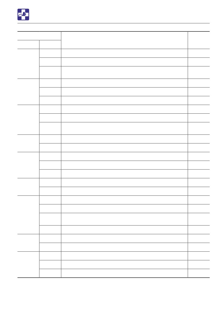
TROUBLESHOOTING
ENGINE ERROR CODE LIST
Error code
Error details
DTC
SPN
FMI
3
EGR low pressure side sensor fault (High voltage)
P0238
4
EGR low pressure side sensor fault (Low voltage)
P0237
102
EGR low pressure side sensor fault (Abnormal learning
13
P0236
value)
3
EGR high pressure side sensor fault (High voltage)
P0473
1209
4
EGR high pressure side sensor fault (Low voltage)
P0472
13
EGR high pressure side sensor (Abnormal learning value)
P0471
3
Cooling water temperature sensor fault (High voltage)
P0118
4
Cooling water temperature sensor fault (Low voltage)
P0117
110
Cooling water temperature sensor temperature abnormal
0
P0217
high (Overheat)
3
New air temperature sensor fault (High voltage)
P0113
172
4
New air temperature sensor fault (Low voltage)
P0112
3
Fuel temperature sensor fault (High voltage)
P0183
174
4
Fuel temperature sensor fault (Low voltage)
P0182
0
Fuel temperature sensor temperature abnormal high
P0168
3
Rail pressure sensor fault (High voltage)
P0193
157
4
Rail pressure sensor fault (Low voltage)
P0192
3
DPF differential pressure sensor fault (High voltage)
P2455
4
DPF differential pressure sensor fault (Low voltage)
P2454
3251
DPF differential pressure sensor differential pressure
0
P2452
abnormal high
13
DPF differential pressure sensor (Abnormal learning value)
P2453
3
DPF high pressure side sensor fault (High voltage)
P1455
3609
4
DPF high pressure side sensor fault (Low voltage)
P1454
3
DPF inlet temperature sensor fault (High voltage)
P1428
3242
4
DPF inlet temperature sensor fault (Low voltage)
P1427
0
DPF inlet temperature sensor temperature abnormal high
P1436
6-15
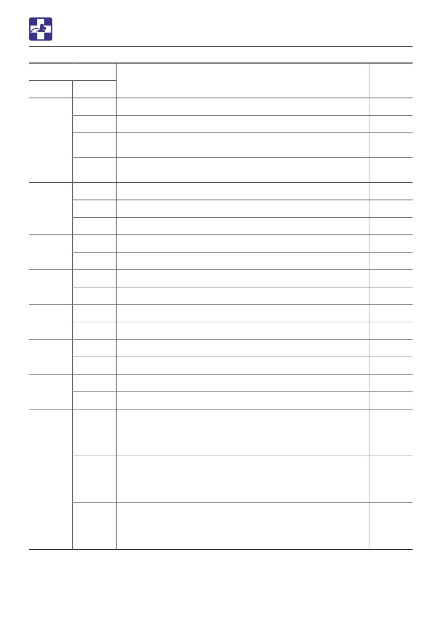
TROUBLESHOOTING
ENGINE ERROR CODE LIST
Error code
Error details
DTC
SPN
FMI
3
DPF intermediate temperature sensor fault (High voltage)
P1434
4
DPF intermediate temperature sensor fault (Low voltage)
P1435
3250
DPF intermediate temperature sensor temperature
1
P0420
abnormal low temperature
DPF intermediate temperature sensor temperature
0
P1426
abnormal high (Post-injection failure)
3
Atmospheric pressure sensor fault (High voltage)
P2229
108
4
Atmospheric pressure sensor fault (Low voltage)
P2228
10
Atmospheric pressure sensor characteristic fault
P1231
3
EGR gas temperature sensor fault (High voltage)
P041D
412
4
EGR gas temperature sensor fault (Low voltage)
P041C
3
Intake manifold temperature sensor fault (High voltage)
P040D
105
4
Intake manifold temperature sensor fault (Low voltage)
P040C
3
Exhaust manifold temperature sensor fault (High voltage)
P0546
173
4
Exhaust manifold temperature sensor fault (Low voltage)
P0545
7
Main relay contact stuck
P068B
1485
2
Main relay early opening
P068A
5
Startup assist relay interrupted
P0543
522243
6
Startup assist relay GND interrupted
P0541
P0204
(4TNV),
5
Injector 1 open circuit (Inherent location of the injector)
P0203
(3TNV)
651
P0271
(4TNV),
(4TNV),
6
Injector 1 coil short circuit
652
P0268
(3TNV)
(3TNV)
P1271
(4TNV),
3
Injector 1 short circuit
P1262
(3TNV)
6-16
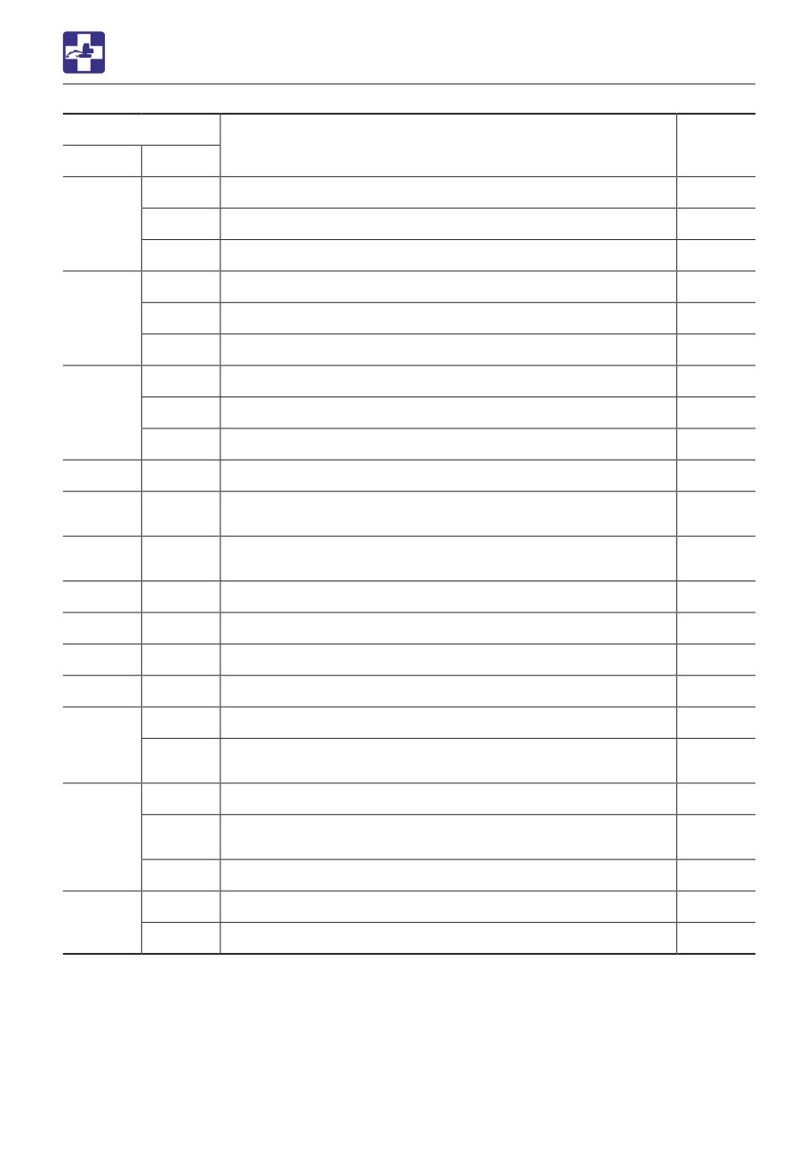
TROUBLESHOOTING
ENGINE ERROR CODE LIST
Error code
Error details
DTC
SPN
FMI
5
Injector 2 open circuit (Inherent location of the injector)
P0202
653
6
Injector 2 coil short circuit
P0265
3
Injector 2 short circuit
P1265
5
Injector 3 open circuit (Inherent location of the injector)
P0201
654
6
Injector 3 coil short circuit
P0262
3
Injector 3 short circuit
P1262
5
Injector 4 open circuit (Inherent location of the injector)
P0203
652
6
Injector 4 coil short circuit
P0268
3
Injector 4 short circuit
P1268
4257
12
Injector drive IC error
P0611
Injector drive circuit (Bank 1) short circuit
2797
6
P1146
(4TN: Common circuit for No.1, No.4 and all 3TN cylinders)
Injector drive circuit (Bank 2) short circuit
2798
6
P1149
(4TN: Circuit for No.2 and No.3 cylinders)
523462
13
IQA corrected injection amount for injector 1 error
P1648
523463
13
IQA corrected injection amount for injector 2 error
P1649
523464
13
IQA corrected injection amount for injector 3 error
P1650
523465
13
IQA corrected injection amount for injector 4 error
P1651
3
High-pressure pump drive circuit (Low side VB short-circuit)
P1641
522571
High-pressure pump drive circuit (Low side GND short-
6
P1643
circuit)
3
High-pressure pump drive circuit (High side VB short-circuit)
P0629
High-pressure pump drive circuit (High side GND short-
633
6
P1642
circuit)
5
High-pressure pump drive circuit (Open circuit)
P0627
6
High-pressure pump drive circuit (Drive current (high level))
P062A
522572
11
High-pressure pump drive circuit (Pump overload error)
P1645
6-17
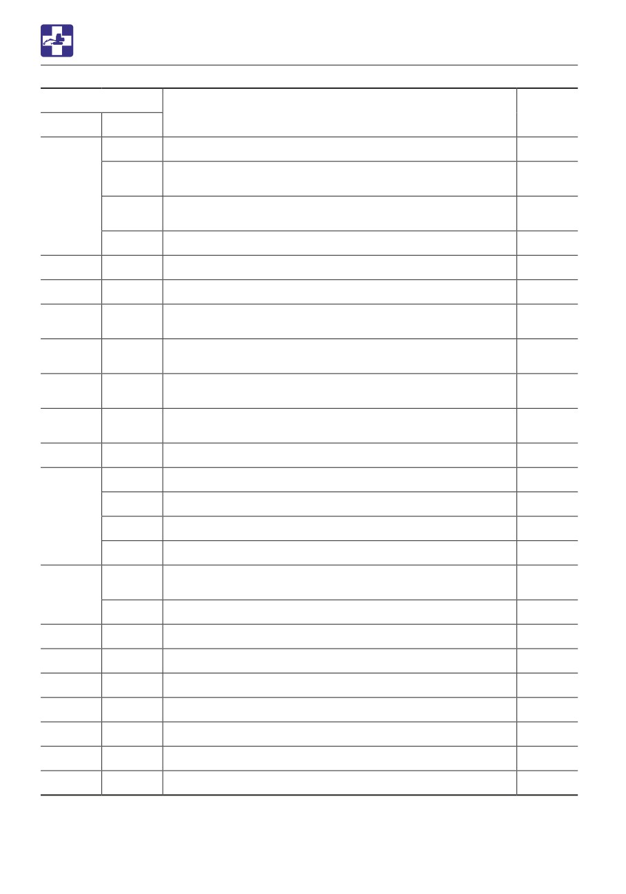
TROUBLESHOOTING
ENGINE ERROR CODE LIST
Error code
Error details
DTC
SPN
FMI
0
Actual rail pressure rise error
P0088
Rail pressure deviation error during the actual rail pressure
18
P0094
drop
157
Rail pressure deviation error during the actual rail pressure
15
P0093
rise
16
PLV open valve
P000F
523469
0
Rail pressure fault (The times of PLV valve opening error)
P1666
523470
0
Rail pressure fault (The time of PLV valve opening error)
P1667
Rail pressure fault (The actual rail pressure is too high
523489
0
P1668
during PRV limp home)
Rail pressure fault (Controlled rail pressure error after PLV
523468
9
P1665
valve opening)
Rail pressure fault (Injector B/F temperature error during
523491
0
P1669
PLV4 limp home)
Rail pressure fault (Operation time error during RPS limp
523460
7
P1670
home)
190
16
Overspeed
P0219
5
No-load of throttle valve drive H bridge circuit
P0660
3
Power short circuit of throttle valve drive H bridge output 1
P1658
2950
4
GND short circuit of throttle valve drive H bridge output 1
P1659
6
Overload on the drive H bridge circuit of throttle valve
P1660
VB Power short circuit of throttle valve drive H bridge output
3
P1661
2
2951
4
GND short circuit of throttle valve drive H bridge output 2
P1662
522596
9
TSC1 (CAN message) reception time out (SA1)
U0292
522597
9
TSC1 (CAN message) reception time out (SA2)
U1301
522599
9
Y_ECR1 (CAN message) reception time out
U1292
522600
9
Y_EC (CAN message) reception time out
U1293
522601
9
Y_RSS (CAN message) reception time out
U1294
522603
9
VH (CAN message) reception time out
U1296
522605
9
Y_ECM3 (CAN message) reception time out
U1298
6-18
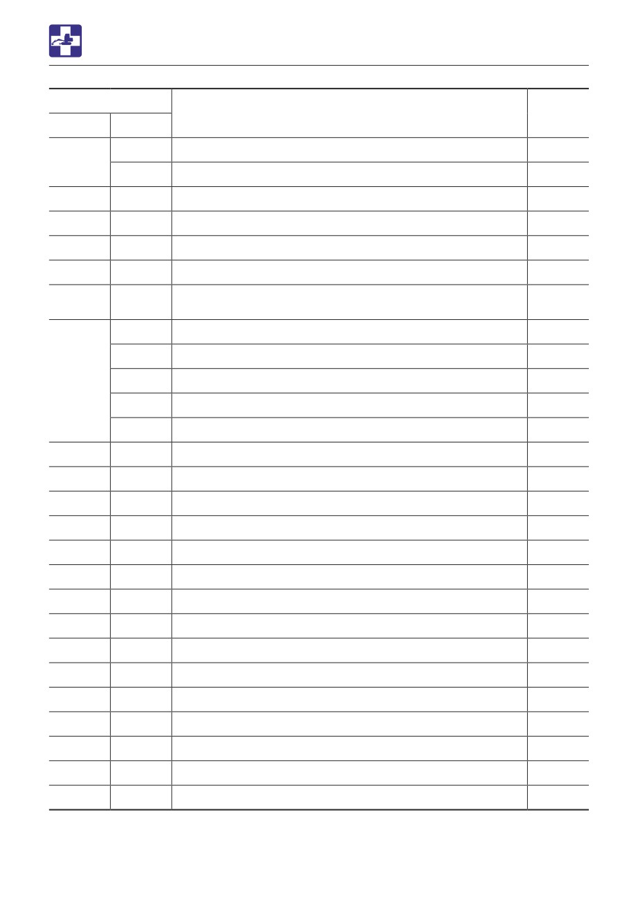
TROUBLESHOOTING
ENGINE ERROR CODE LIST
Error code
Error details
DTC
SPN
FMI
31
VI (CAN message) reception time out
U0168
237
13
VI (CAN message) reception data fault
U3002
522609
9
Y_ETCP1 (CAN message) reception time out
U1300
522618
9
EBC1 (CAN message) reception time out
U1302
522619
9
Y_DPFIF (CAN message) reception time out
U1303
522610
9
CAN1 (for EGR): Reception time out
U010B
Exhaust throttle (CAN message from the exhaust throttle
522611
9
U1107
time out)
0
EGR over-voltage fault
P0404
1
EGR under-voltage fault
P1404
2791
7
EGR feedback malfunction
P1409
9
EGR ECM data fault
U0401
12
Open circuit between the EGR motor coils
P0403
522579
12
Short circuit between the EGR motor coils
P1405
522580
12
EGR position sensor malfunction
P0488
522581
7
EGR stuck open valve malfunction
P148A
522582
7
EGR initialization malfunction
P049D
522183
1
EGR high temperature thermistor malfunction
P1410
522184
1
EGR low temperature thermistor malfunction
P1411
522617
12
EGR target value out of range
U1401
522746
12
Exhaust throttle (Voltage fault)
P1438
522747
12
Exhaust throttle (Motor fault)
P1439
522748
12
Exhaust throttle (Sensor system fault)
P1440
522749
12
Exhaust throttle (MPU fault)
P1441
522750
12
Exhaust throttle (PCB fault)
P1442
522751
19
Exhaust throttle (CAN fault)
P1443
630
12
EEPROM memory deletion error
P0601
522576
12
EEPROM memory read error
P160E
6-19
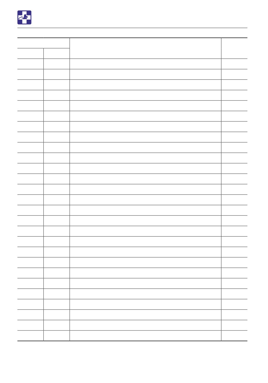
TROUBLESHOOTING
ENGINE ERROR CODE LIST
Error code
Error details
DTC
SPN
FMI
522578
12
EEPROM memory writing error
P160F
522585
12
ECU internal fault (CY146 SPI communication fault)
P1613
522588
12
ECU internal fault (Excessive voltage of supply 1)
P1608
522589
12
ECU internal fault (Insufficient voltage of supply 1)
P1617
522590
12
ECU internal fault (Sensor supply voltage error 1)
P1609
522591
12
ECU internal fault (Sensor supply voltage error 2)
P1618
522592
12
ECU internal fault (Sensor supply voltage error 3)
P1619
522744
4
ECU internal fault (Actuator drive circuit 1 short to ground)
P1626
522994
4
ECU internal fault (Actuator drive circuit 2 short to ground)
P1633
523471
6
ECU internal fault (Actuator drive circuit 3 short to ground)
P1467
523473
12
ECU internal fault (AD converter fault 1)
P1469
523474
12
ECU internal fault (AD converter fault 2)
P1470
523475
12
ECU internal fault (External monitoring IC and CPU fault 1)
P1471
523476
12
ECU internal fault (External monitoring IC and CPU fault 2)
P1472
523477
12
ECU internal fault (ROM fault)
P1473
523478
12
ECU internal fault (Shutoff path fault 1)
P1474
523479
12
ECU internal fault (Shutoff path fault 2)
P1475
523480
12
ECU internal fault (Shutoff path fault 3)
P1476
523481
12
ECU internal fault (Shutoff path fault 4)
P1477
523482
12
ECU internal fault (Shutoff path fault 5)
P1478
523483
12
ECU internal fault (Shutoff path fault 6)
P1479
523484
12
ECU internal fault (Shutoff path fault 7)
P1480
523485
12
ECU internal fault (Shutoff path fault 8)
P1481
523486
12
ECU internal fault (Shutoff path fault 9)
P1482
523487
12
ECU internal fault (Shutoff path fault 10)
P1483
523488
0
ECU internal fault (Recognition error of engine speed)
P1484
522323
0
Air cleaner clogged alarm
P1101
6-20
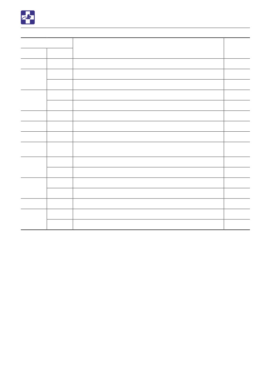
TROUBLESHOOTING
ENGINE ERROR CODE LIST
Error code
Error details
DTC
SPN
FMI
522329
0
Oil/water separator alarm
P1151
5
Charge switch (Charge switch open circuit)
P1562
167
1
Charge switch (Charge alarm)
P1568
4
Oil pressure switch (Oil pressure switch open circuit)
P1192
100
1
Oil pressure switch (Low oil pressure fault alarm)
P1198
522573
0
DPF overaccumulation (Method C)
P2463
522574
0
DPF overaccumulation (Method P)
P1463
522575
7
DPF regeneration defect (Stationary regeneration failure)
P2458
DPF regeneration defect (Stationary regeneration not-
522577
11
P2459
performed)
16
DPF OP interface (Ash cleaning request 1)
P242F
3720
0
DPF OP interface (Ash cleaning request 2)
P1420
16
DPF OP interface (Stationary regeneration standby)
P1421
3719
0
DPF OP interface (Backup mode)
P1424
3695
14
DPF OP interface (Reset regeneration prohibited)
P1425
9
DPF OP interface (Recovery regeneration failure)
P1445
3719
7
DPF OP interface (Recovery regeneration prohibition)
P1446
6-21
TROUBLESHOOTING
OTHER SYMPTOMS
OTHER SYMPTOMS
For symptoms not included in the table below or if the problem persists after the proper
remedies have been taken, consult your sales or service dealer.
Symptoms
Major causes
Remedies
Left and right operating levers
• Insufficient grease on the
• Grease the levers.
do not move smoothly
left and right operating
Refer to page 5-62.
levers
Travel levers, blade lever and
• Insufficient grease on travel
• Grease the levers and
pedals do not move smoothly
levers, blade lever and
pedals.
pedals
Refer to page 5-62.
Operation of hoe attachment,
• Safety lock lever is raised
• Lower (release) the safety
dozer blade, auxiliary
(locked)
lock lever.
hydraulics, slewing or
Refer to page 2-58.
traveling is not possible.
• Fuse is blown
• Replace the fuse.
Refer to page 6-6.
Digging force is insufficient
• Hydraulic oil level too low
• Add to the specified level.
Refer to page 5-22.
• Hydraulic oil is not warm
• Perform the warm-up.
enough
Refer to pages 3-8 to 3-9.
• Air cleaner is clogged
• Clean the air cleaner.
Refer to page 5-38.
• Hydraulic oil is not of
• Replace the hydraulic oil.
suitable type
Refer to page 5-53.
Traveling is not possible or
• Stones or foreign objects
• Remove the foreign object.
not smooth
are stuck
Machine veers to the right/left
• Stones or foreign objects
• Remove the foreign object.
are stuck
• Crawler belt tension is
• Check and adjust (ask your
faulty.
sales or service dealer).
Refer to pages 5-28 to
5-29.
Travel speed cannot be
• Fuse is blown
• Replace the fuse.
changed
Refer to page 6-6.
Slewing is not possible or not
• Insufficient grease on slew
• Grease the bearing.
smooth
bearing
Refer to page 5-30.
Hydraulic oil temperature is
• Hydraulic oil level too low
• Add up to the specified
too high
level.
Refer to page 5-22.
6-22

TROUBLESHOOTING
OTHER SYMPTOMS
Symptoms
Major causes
Remedies
Starter motor turns but
• Insufficient fuel
• Add fuel.
engine does not start
Refer to page 5-21.
• Air in fuel system
• Bleed air.
Refer to page 6-8.
• Water in fuel system
• Drain water.
Refer to page 5-30.
• Fuel is frozen.
• Warm the fuel pipe with hot
water or wait until the
ambient temperature
becomes high.
• Engine control system is
• Adjust or repair (ask your
faulty.
sales or service dealer).
• Fuel line is faulty.
• Adjust or repair (ask your
sales or service dealer).
• Preheating device is faulty.
• Adjust or repair (ask your
sales or service dealer).
Crawlers come off
• Crawlers too loose
• Check and adjust (ask your
sales or service dealer).
Refer to pages 5-28 to
5-29.
Engine exhaust is white or
• Excessive engine oil
• Adjust to the specified level.
bluish
Refer to page 5-19.
• Insufficient engine warm-up.
• Perform the warm-up
operation.
Refer to page 3-5.
• Engine control system is
• Adjust or repair (ask your
faulty.
sales or service dealer).
• Fuel line is faulty.
• Adjust or repair (ask your
sales or service dealer).
• Prolonged idling (approx.
• Increase the engine RPM
two hours or more)
and check for smoke.
• Poor fuel
• Replace the fuel.
6-23
TROUBLESHOOTING
OTHER SYMPTOMS
Symptoms
Major causes
Remedies
Engine exhaust is
• Air cleaner is clogged
• Clean the air cleaner.
occasionally black
Refer to page 5-38.
• Engine control system is
• Adjust or repair (ask your
faulty.
sales or service dealer).
• Fuel line is faulty.
• Adjust or repair (ask your
sales or service dealer).
• Clogging in the exhaust line.
• Adjust or repair (ask your
sales or service dealer).
• DPF is faulty.
• Adjust or repair (ask your
sales or service dealer).
Irregular noise is produced
• Low quality fuel is being
• Replace the fuel.
from the engine
used
(combustion or mechanical
• Engine is overheating
• Refer to “If the engine
noise)
overheats” on page 6-3.
• Damage inside the muffler
• Replace the muffler.
For replacement, ask your
sales or service dealer.
6-24
TROUBLESHOOTING
LOWERING THE BOOM TO THE GROUND
spurt out if wrongly handled.
LOWERING THE BOOM TO
THE GROUND
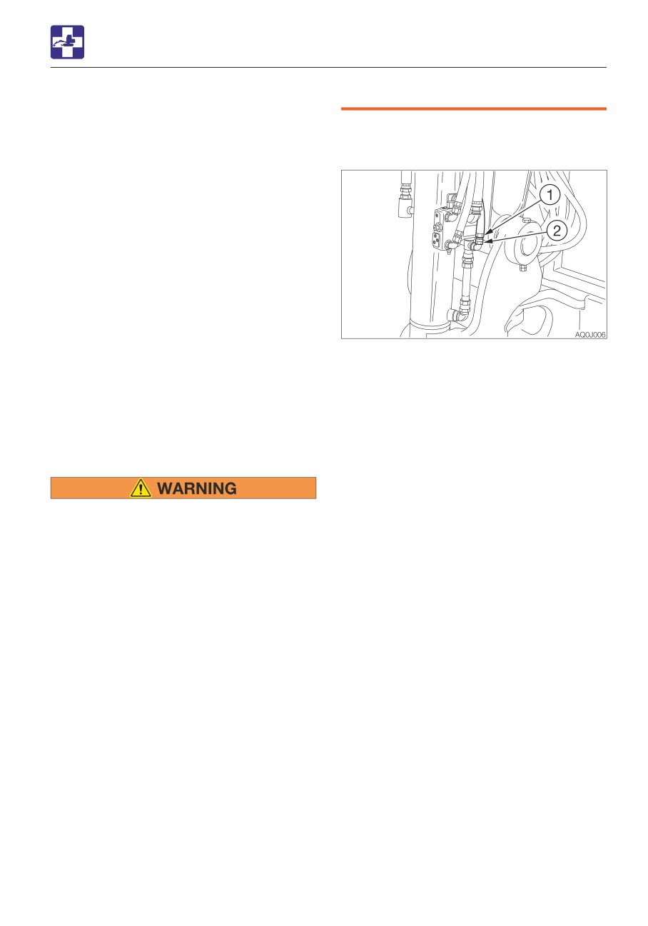
Emergency shut-off valve
If the hoe attachment must be lowered to the
ground while the engine is stopped, use the
following procedure.
Procedure 1 (machines with an
accumulator)
Perform this operation within 10 minutes
after the engine stopping.
1. Sit at the operator’s seat.
2. Turn the starter switch to the ON position.
3. Lower the safety lock lever to the unlock
position
4. Slowly push the operating lever forward to
1. Place a pan under the hose to catch the
lower the boom.
waste oil.
2. Hold the hose fitting (1) with a wrench and
Procedure 2 (machines without an
slowly loosen the hose nut (2) with another
accumulator)
wrench.
This operation is dangerous and requires
3. The oil in the boom cylinder is drained and
experience. Ask your sales or service dealer
the hoe attachment is lowered.
for it.
4. After the hoe attachment is lowered to the
ground, check the safety and stability of
the machine.
• Stop the engine and allow the machine
5. Hold the hose fitting (1) with a wrench and
to cool down before performing
tighten the hose nut (2) with another
maintenance.
wrench.
· The engine and the hydraulic system
· Tightening torque: 31.4 N·m (23.1 ft-lb.)
and many other parts of the machine
are hot immediately after the engine is
stopped. Touching these parts will
cause burns.
· The hydraulic oil is also hot and under
high pressure immediately after the
engine is stopped.
Be careful when loosening the caps or
plugs. Working on the machine under
these conditions could result in burns
or injuries due to the hot oil spurting
out.
• Keep away from the working area when
the hoe attachment is lowered. You may
be hit by dirt falling out of the bucket or
the hoe attachment as it drops.
• Slowly turn the hose nut and lower the
boom at a slow pace.
• Do not loosen or remove the hoses not
located in the specified places. Oil may
6-25
TROUBLESHOOTING
TOWING
Towing the machine
TOWING
Use the procedure described below to tow
heavy objects or the machine itself if it
should get stuck in the mud and not be able
When towing, serious injury or death
to get out on its own.
could result, if performed incorrectly or
the wire rope being used is inappropriate
or not properly inspected.
• It becomes dangerous if the wire rope
breaks or becomes disengaged. Use a
wire rope appropriate for the required
tractive force.
• Do not use a wire rope that is kinked,
twisted or otherwise damaged.
• Do not apply heavy loads abruptly to
the wire rope.
• Wear safety gloves when handling the
wire rope.
• Permissible forces: 83.2 kN (18700 lbf)
• Make sure there is an operator on the
Do not tow using only a towing hole on one
machine being towed as well as on the
side.
machine that is towing.
• Never tow on slopes.
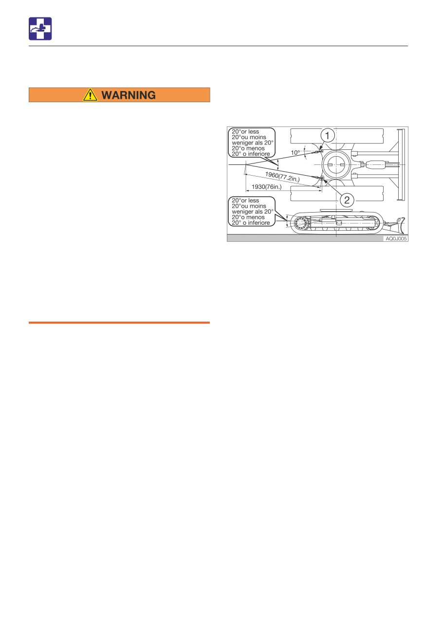
1. Attach the wire rope to the shackle (1).
• Do not let anyone come near to the wire
2. Fasten the shackle (1) to the towing holes
rope while towing.
(2).
3. Make sure that the wire rope is at a cone
IMPORTANT: Do not tow a machine if its
angle of 20° or less to the travel frame.
engine does not start or if the machine
4. Move the machine to tension the wire
does not run. Doing so could damage the
rope.
machine being towed.
5. Operate the machine slowly and tow.
IMPORTANT: Be sure to follow the steps
below closely when using the towing hole
to tow. Failure to heed even one of the
steps may cause damage to the towing
hole or other parts of the frame.
6-26
TROUBLESHOOTING
IF THE CAB OR CANOPY IS DAMAGED
IF THE CAB OR CANOPY IS
DAMAGED
Immediately replace the damaged cab or
canopy. Serious injury or death may occur
if the machine is operated with damaged
cab/canopy.
Do not operate the machine until the
replacement is complete. Do not try to
repair the damaged cab or canopy by
welding. Doing so could endanger the
safety of the cab/canopy.
Canopy part number: 05584-00085
Cab part number: 05586-03100
6-27
6-28
SPECIFICATIONS
7-1
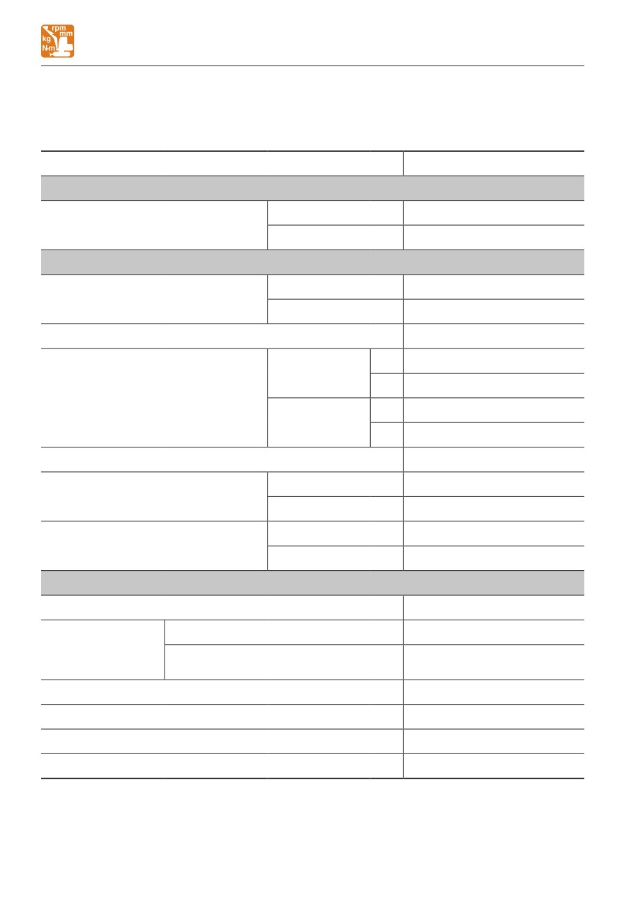
SPECIFICATIONS
BASIC SPECIFICATIONS
BASIC SPECIFICATIONS
<Applicable machine models 126000002 or later>
Type
Cab
MASS
Rubber crawlers
5735 (12645)
Operating mass
kg (lb)
Steel crawlers
5920 (13050)
PERFORMANCE
Heaped
0.168
(5.93)
Bucket capacity
m3 (cu. ft.)
(Standard bucket)
Struck
0.127
(4.48)
Slew speed
min-1 (rpm)
9.4
(9.4)
1st
2.8
(1.74)
Rubber crawlers
2nd
4.9
(3.04)
Travel speed
km/h (mph)
1st
2.6
(1.62)
Steel crawlers
2nd
4.6
(2.86)
Gradeability
(degrees)
30
Rubber crawlers
31.5
(4.57)
Ground pressure
kPa (psi)
Steel crawlers
32.7
(4.74)
Sound power level
LWA 97
Noise level
dB (A)
Sound pressure level
LpA 80
ENGINE
Manufacturer and model
Yanmar 4TNV84T-BPTB
Net (ISO 14396)
kW/min-1 (hp/rpm)
34.3/2400 (46/2400)
Rated output
Net (ISO 9249/
kW/min-1 (hp/rpm)
32.4/2400 (43.4/2400)
SAEJ1349)
Displacement
ml (cu.in.)
1995 (121.7)
Starter
V-kW
12-2.3
Alternator
V-kW
12-0.66
Battery (IEC 60095-1)
V-A·h
12-90
7-2
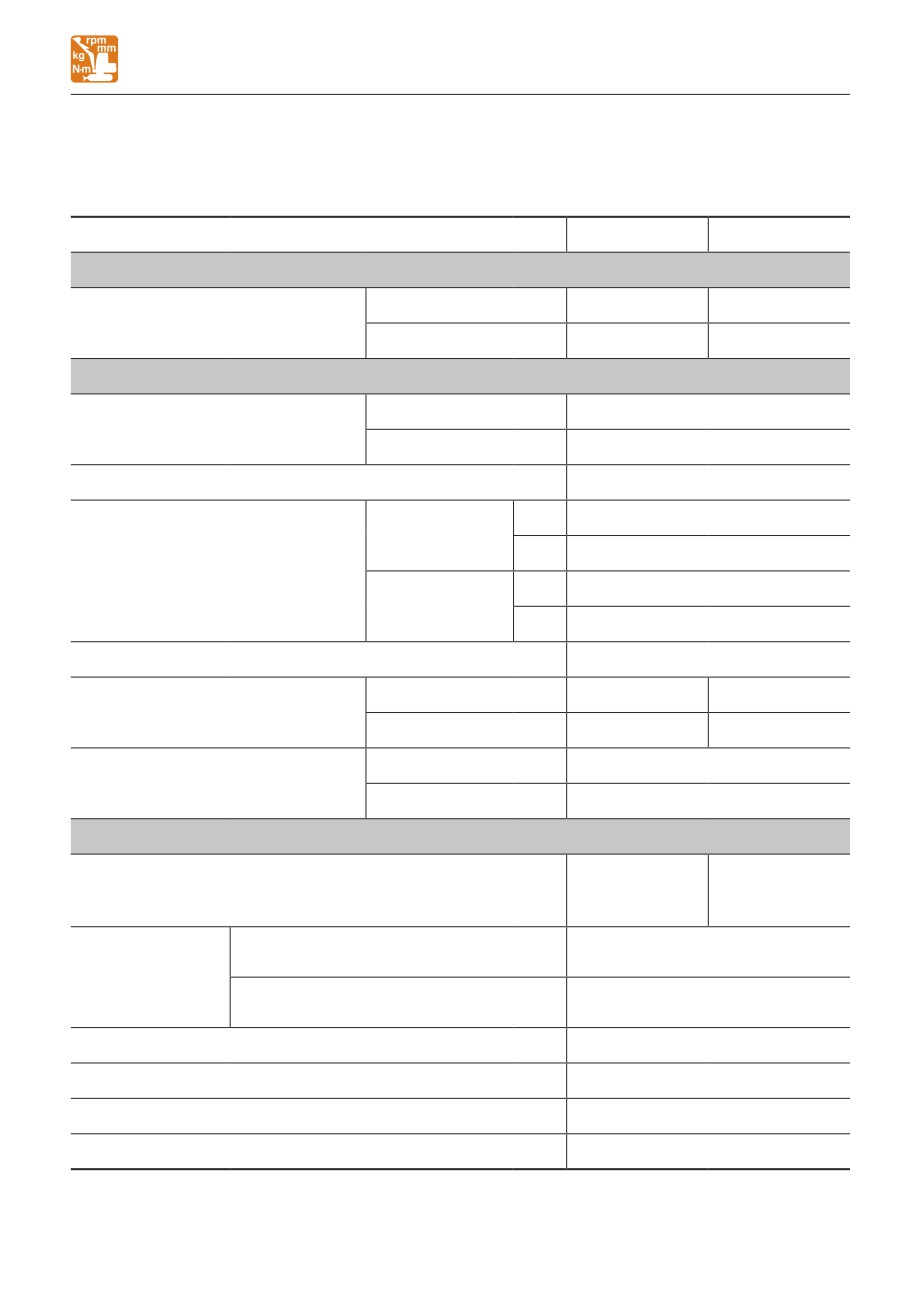
SPECIFICATIONS
BASIC SPECIFICATIONS
<Applicable machine models 126100003 or later>
Type
Canopy
Cab
MASS
Rubber crawlers
5500 (12125)
5735 (12645)
Operating mass
kg (lb)
Steel crawlers
5685 (12535)
5920 (13050)
PERFORMANCE
Heaped
0.168
(5.93)
Bucket capacity
m3 (cu. ft.)
(Standard bucket)
Struck
0.127
(4.48)
Slew speed
min-1 (rpm)
9.4
(9.4)
1st
2.8
(1.74)
Rubber crawlers
2nd
4.9
(3.04)
Travel speed
km/h (mph)
1st
2.6
(1.62)
Steel crawlers
2nd
4.6
(2.86)
Gradeability
(degrees)
30
Rubber crawlers
30.2
(4.38)
31.5
(4.57)
Ground pressure
kPa (psi)
Steel crawlers
31.4
(4.55)
32.7
(4.74)
Sound power level
LWA 97
Noise level
dB (A)
Sound pressure level
LpA 75
ENGINE
Yanmar
Yanmar
Manufacturer and model
4TNV86CT-
4TNV86CT-
PTB I
PTB
Net (ISO
kW/min-1 (hp/rpm)
35.5/2400 (47.6/2400)
14396)
Rated output
Net (ISO 9249/
kW/min-1 (hp/rpm)
33.6/2400 (45.1/2400)
SAEJ1349)
Displacement
ml (cu.in.)
2091 (127.6)
Starter
V-kW
12-2.3
Alternator
V-kW
12-0.66
Battery (IEC 60095-1)
V-A·h
12-90
7-3
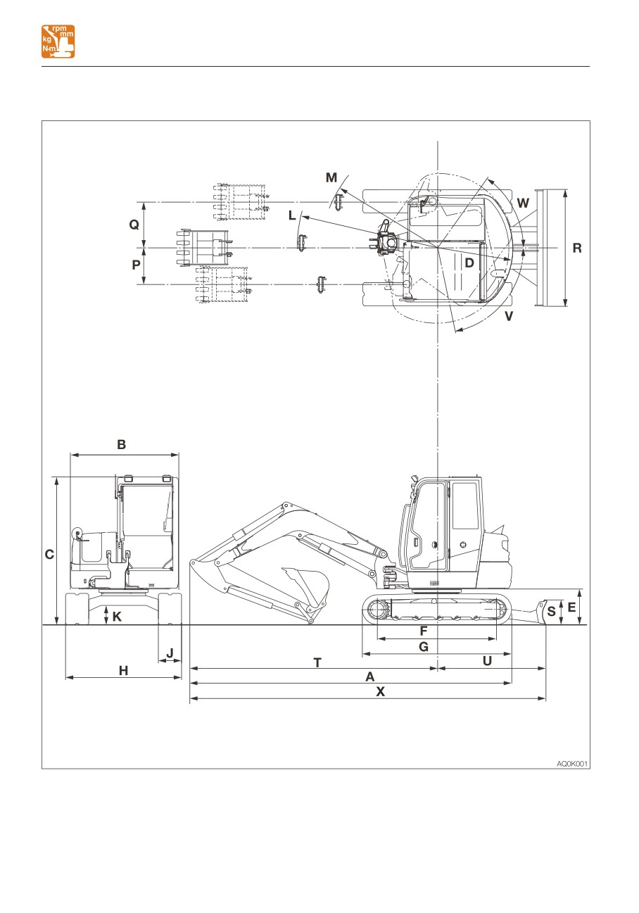
SPECIFICATIONS
MACHINE DIMENSIONS
MACHINE DIMENSIONS
7-4
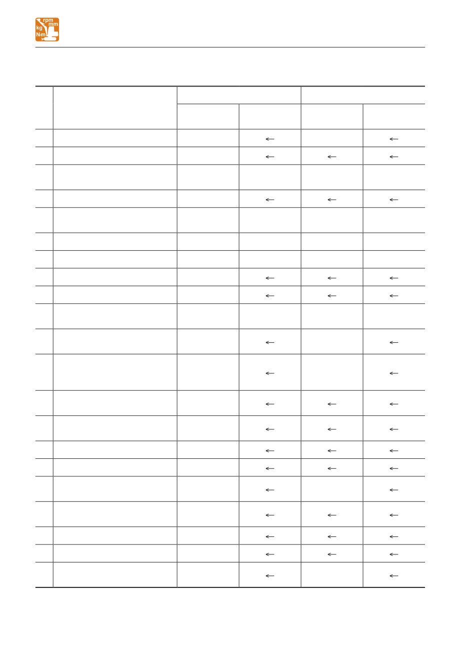
SPECIFICATIONS
MACHINE DIMENSIONS
<Applicable machine models 126000002 or later /126100003 or later>
Unit: mm (inch)
Middle arm
Long arm
Item
Rubber
Steel
Rubber
Steel
crawlers
crawlers
crawlers
crawlers
A
Overall length
5540 (218.0)
5550 (218.5)
B
Upperstructure overall width
1870 (73.6)
2560 (100.8)
2550 (100.4)
2560 (100.8)
2550 (100.4)
C
Overall height
2575 (101.4)**
2565 (101.0)**
2575 (101.4) **
2565 (101.0) **
D
Slew radius
1300 (51.2)
Clearance height under
E
635 (25.0)
625 (24.6)
635 (25.0)
625 (24.6)
upperstructure
F
Crawler base
2050 (80.7)
2035 (80.2)
2050 (80.7)
2035 (80.2)
G
Crawler overall length
2575 (101.3)
2560 (100.8)
2575 (101.3)
2560 (100.8)
H
Crawler overall width
2000 (78.7)
J
Crawler shoe width
400 (15.7)
Ground clearance of
K
330 (13.1)
325 (12.7)
330 (13.1)
325 (12.7)
undercarriage
Minimum radius of
L
2390 (94.0)
2420 (95.4)
equipment and attachment
Minimum radius of
M
equipment at maximum
1945 (76.6)
1975 (77.8)
front offset
Offset distance of bucket
P
655 (25.8)
(right swing)
Offset distance of bucket
Q
785 (31.0)
(left swing)
R
Dozer blade width
2000 (78.7)
S
Dozer blade height
430 (16.9)
Front distance to axis of
T
4240 (166.9)
4255 (167.5)
rotation
Dozer blade distance to axis
1870 (73.6)
U
of rotation
1930 (76.0)*
V
Boom swing angle (Left)
78°
W
Boom swing angle (Right)
55°
Overall length (dozer blade
6110 (240.5)
6125 (241.2)
X
at rear)
6170 (242.9)*
6185 (243.5)*
: With an angle dozer blade
** : Canopy
7-5
SPECIFICATIONS
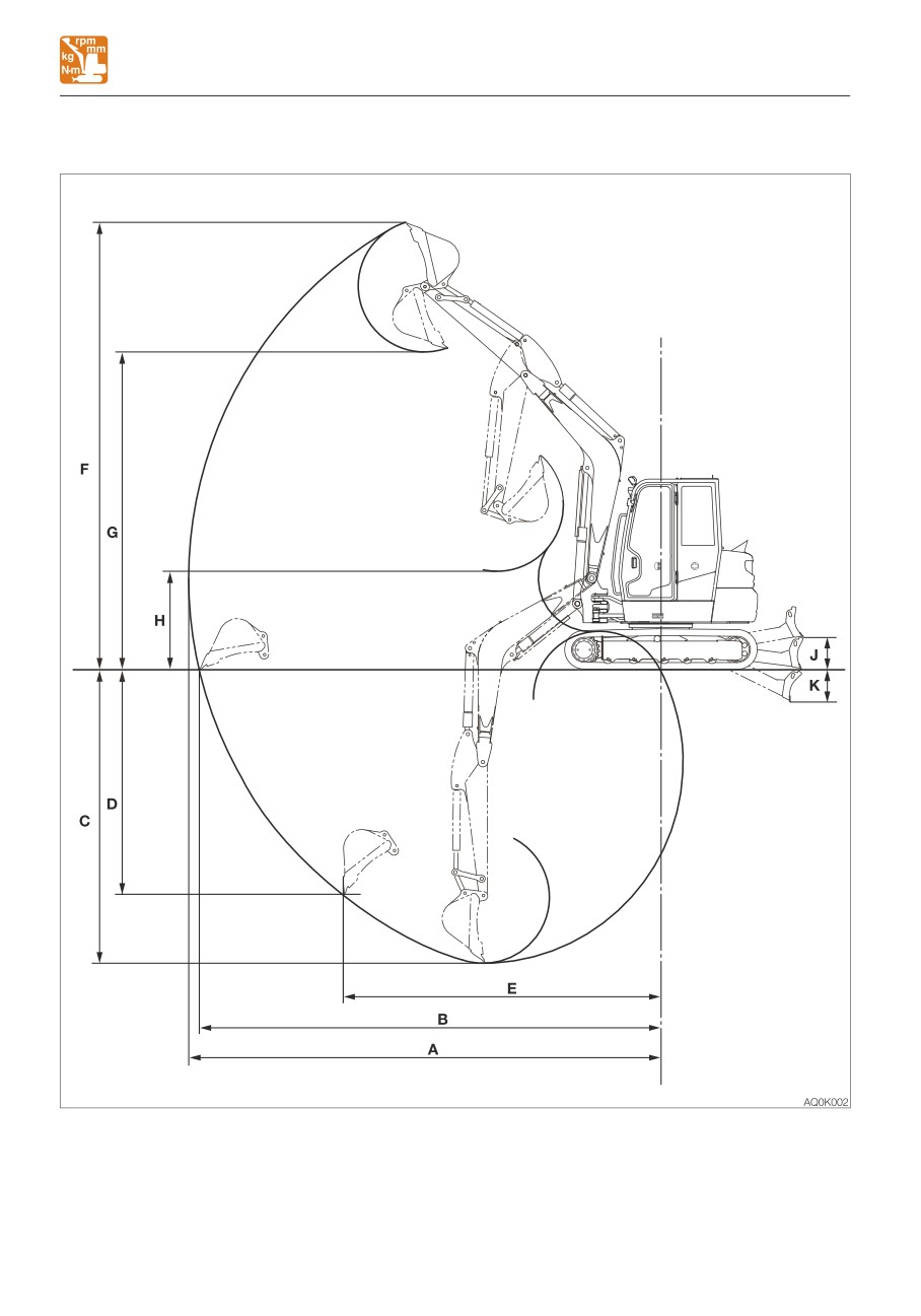
OPERATING RANGES
OPERATING RANGES
7-6
SPECIFICATIONS
OPERATING RANGES
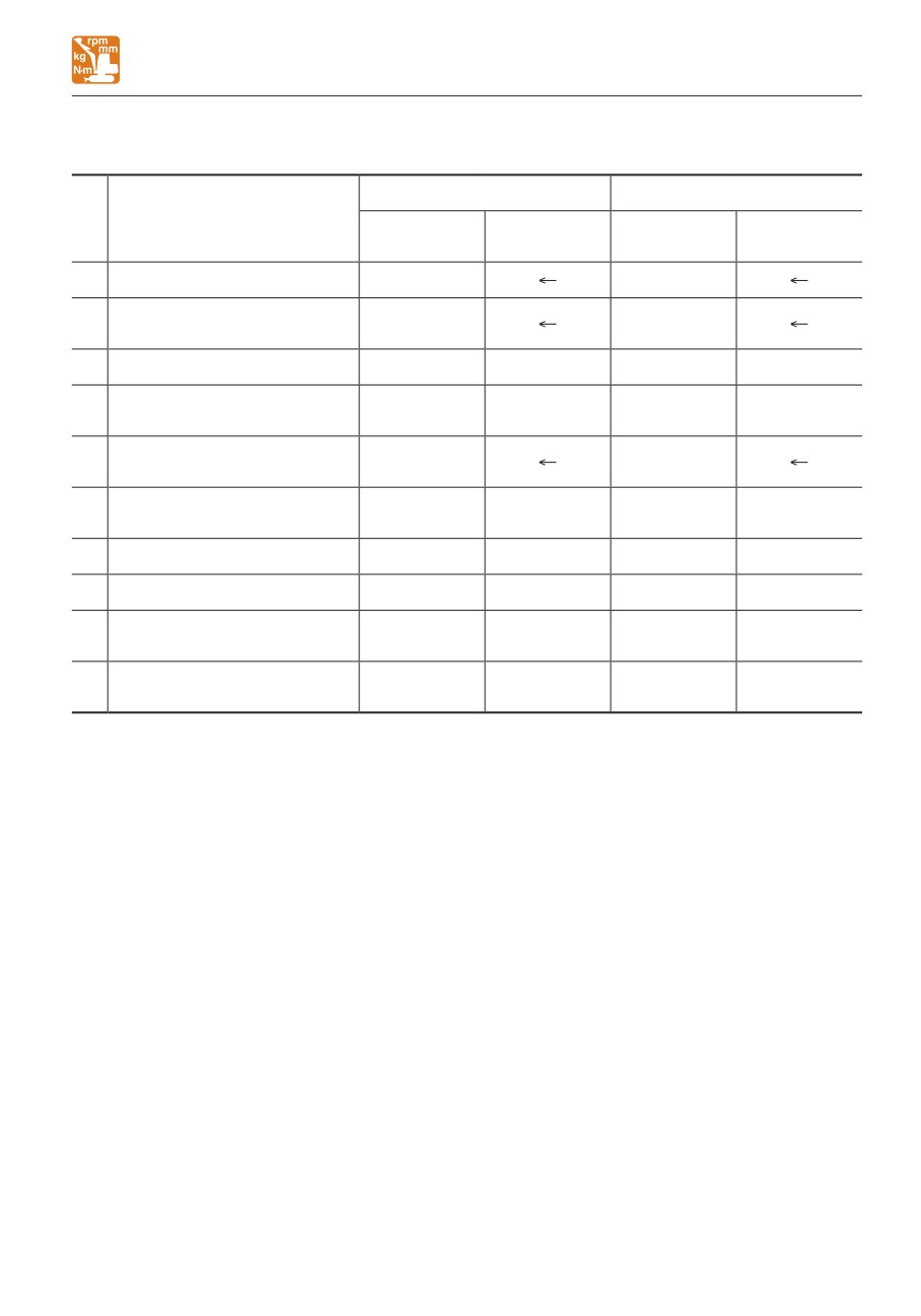
<Applicable machine models 126000002 or later /126100003 or later>
Unit: mm (inch)
Middle arm
Long arm
Item
Rubber
Steel
Rubber
Steel
crawlers
crawlers
crawlers
crawlers
A
Maximum reach
6120 (240.9)
6270 (246.9)
Maximum reach at ground
B
5975 (235.3)
6130 (241.4)
reference plane
C
Maximum digging depth
3735 (147.1)
3745 (147.4)
3895 (153.4)
3905 (153.7)
Maximum vertical digging
D
2830 (111.3)
2835 (111.7)
2980 (117.4)
2990 (117.7)
depth
Reach at maximum vertical
E
4175 (164.3)
4220 (166.1)
digging depth
Maximum height of cutting
F
5835 (229.7)
5825 (229.4)
5940 (233.9)
5930 (233.5)
edge
G
Maximum dumping height
4115 (162.0)
4105 (161.6)
4220 (166.1)
4210 (165.8)
H
Minimum dumping height
1465 (57.6)
1455 (57.3)
1305 (51.5)
1300 (51.1)
430 (16.9)
420 (16.5)
430 (16.9)
420 (16.5)
J
Dozer blade maximum lifting
445 (17.5)*
435 (17.2)*
445 (17.5)*
435 (17.2)*
Dozer blade maximum
430 (16.9)
440 (17.2)
430 (16.9)
440 (17.2)
K
lowering
450 (17.7)*
455 (18.0)*
450 (17.7)*
455 (18.0)*
*: With an angle dozer blade
7-7
MEMO
7-8
SPECIFICATIONS
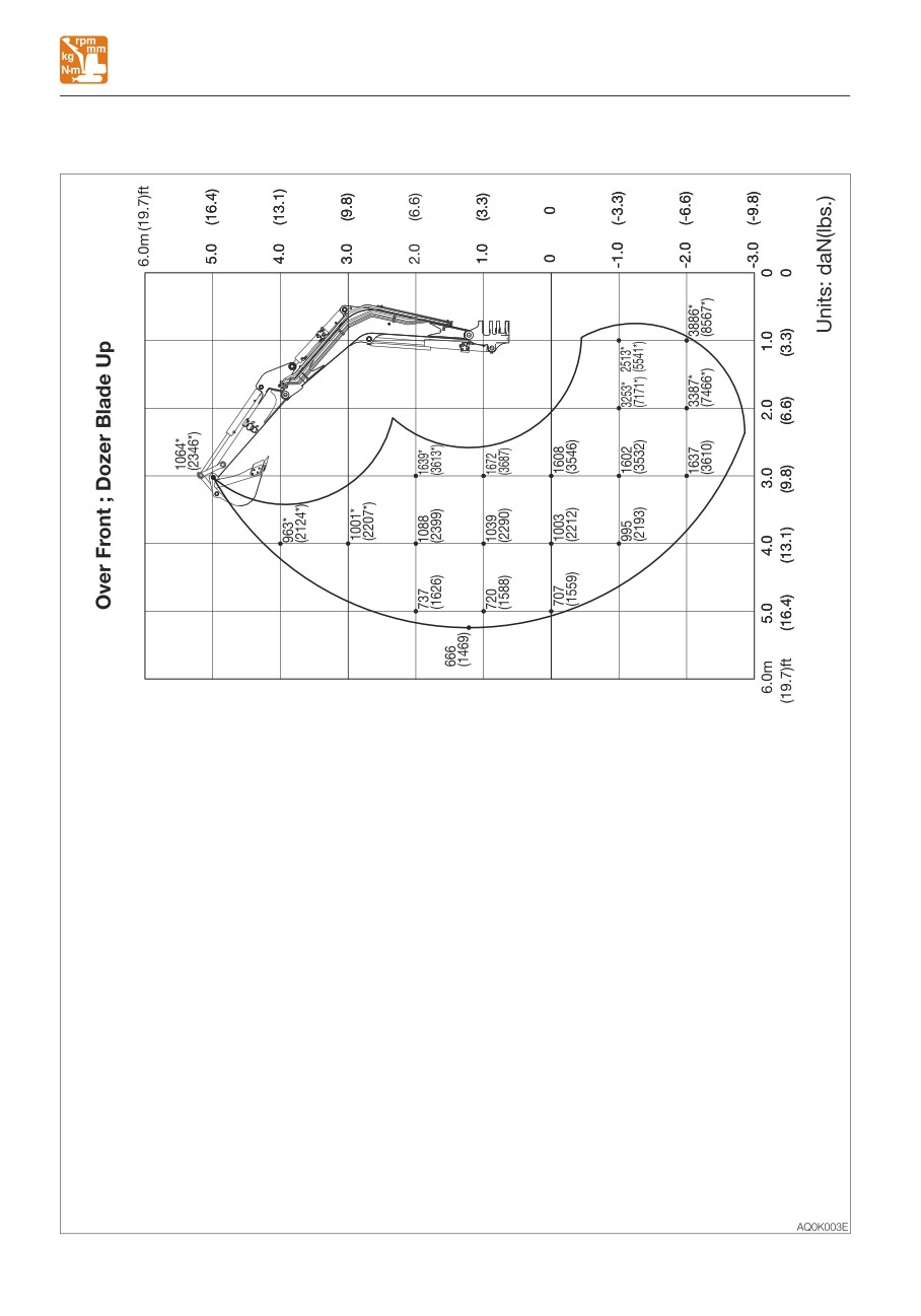
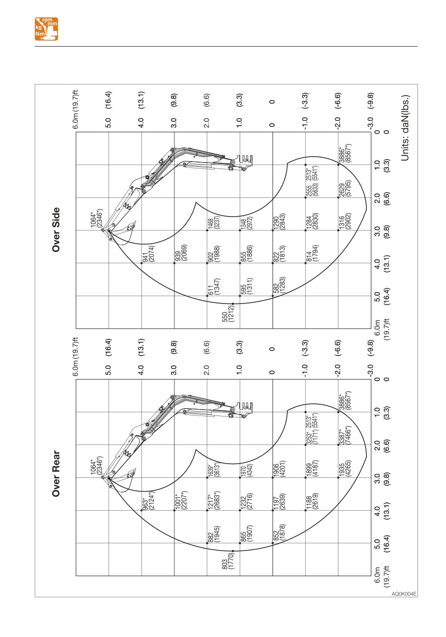
LIFTING CAPACITIES
LIFTING CAPACITIES
Rated lift capacity chart
• Do not attempt to lift or hold any load
• The loads in the charts do not exceed 87%
that is greater than these rated values at
of hydraulic lift capacity or 75% of tipping
their specified load radii and height.
load.
• The rated lift capacities are based on
• Figures marked with an asterisk (*) are
the machine being level and situated on
hydraulically-limited capacities.
a firm supporting surface. For safe
• The mass of slings and any other lifting
lifting, the operator is expected to make
devices shall be deducted from the rated
due allowance for the particular job
load to determine the net load that may be
conditions such as soft or uneven
lifted.
ground, non-level condition, load to the
• The load point is the bucket hinge pin, and
machine sides, hazardous conditions,
the bucket posture is with the standard
experience of personnel, etc. The
bucket completely retracted under the arm.
operator and other personnel should
• Unit: daN (lbs)
fully acquaint themselves with the
operator’s manual furnished by the
Load hooking system
manufacturer before operating this
A load hooking system must be provided
machine. When operating the machine,
with the following capabilities.
the safety rules of the equipment must
1. A system which can withstand twice the
also be followed.
rated lift capacity no matter at what
• Do not travel while lifting a load; It is
position the load is applied.
very dangerous.
2. A system that poses no risk of the lifted
load falling from the hooking device. For
example, equipped with a hook slippage
prevention device.
3. A system that poses no risk of the hooking
system slipping from the hoe attachment.
7-9
SPECIFICATIONS
LIFTING CAPACITIES
<Cab> Middle arm (Applicable machine models 126000002 or later)
7-10
SPECIFICATIONS
LIFTING CAPACITIES
<Cab> Middle arm (Applicable machine models 126000002 or later)
7-11
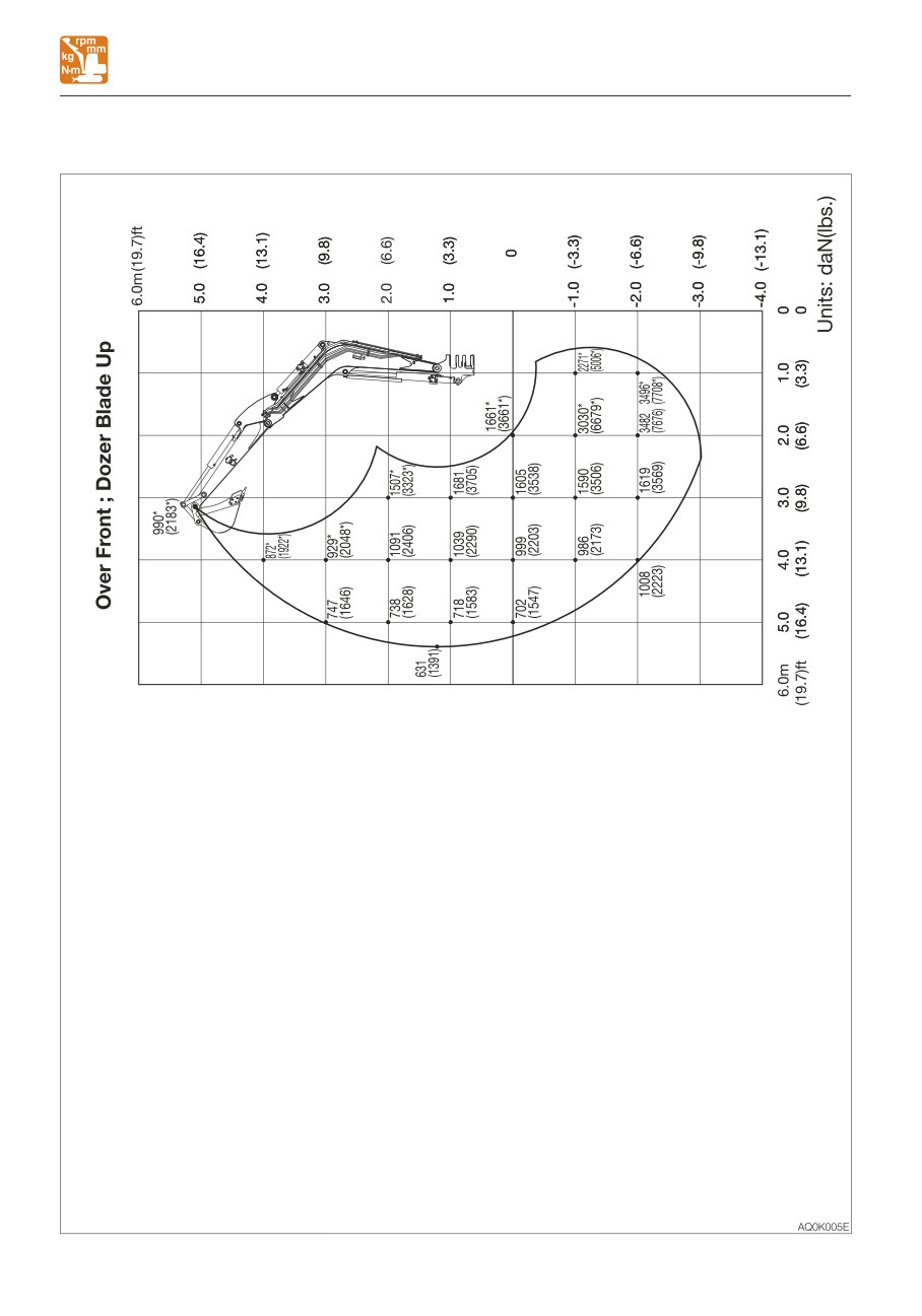
SPECIFICATIONS
LIFTING CAPACITIES
<Cab> Long arm (Applicable machine models 126000002 or later)
7-12
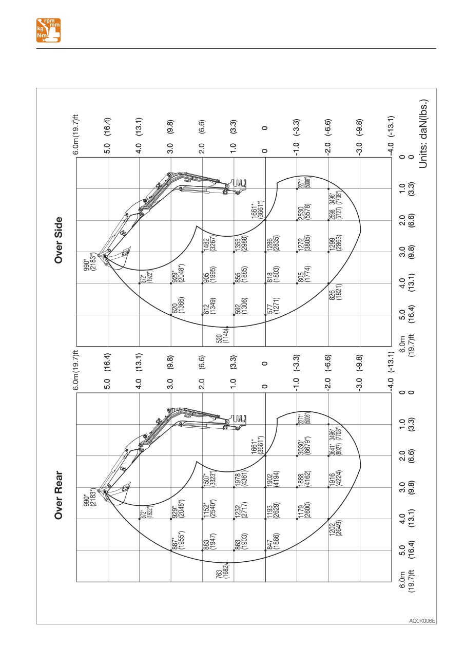
SPECIFICATIONS
LIFTING CAPACITIES
<Cab> Long arm (Applicable machine models 126000002 or later)
7-13
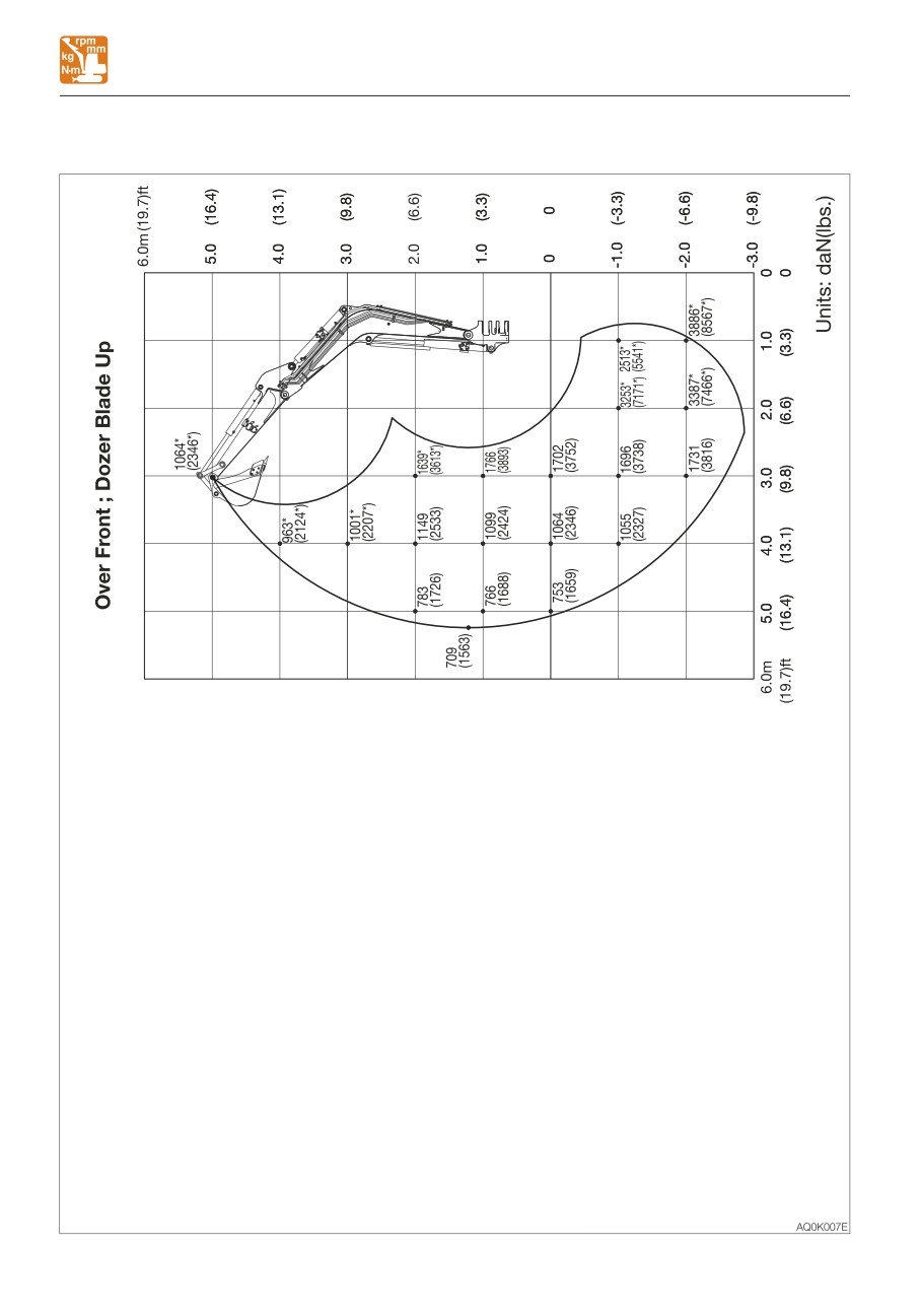
SPECIFICATIONS
LIFTING CAPACITIES
<Cab> Middle arm (Applicable machine models 126100003 or later)
7-14
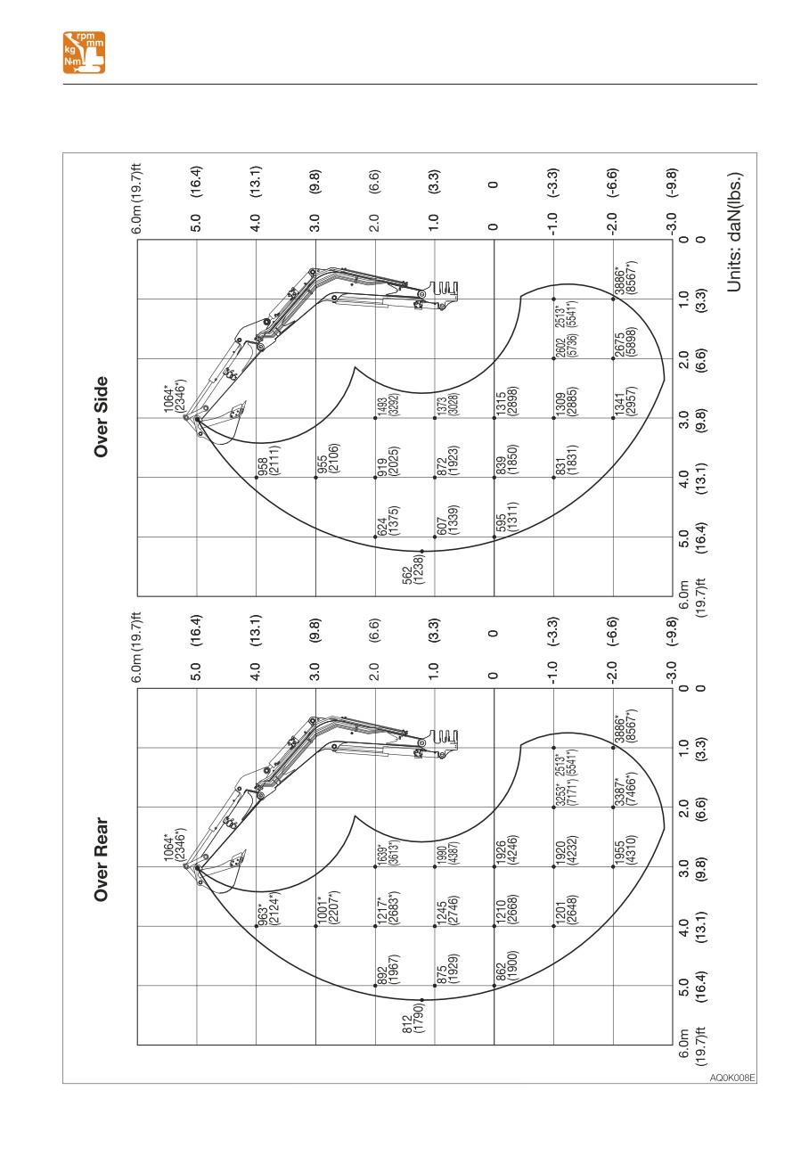
SPECIFICATIONS
LIFTING CAPACITIES
<Cab> Middle arm (Applicable machine models 126100003 or later)
7-15
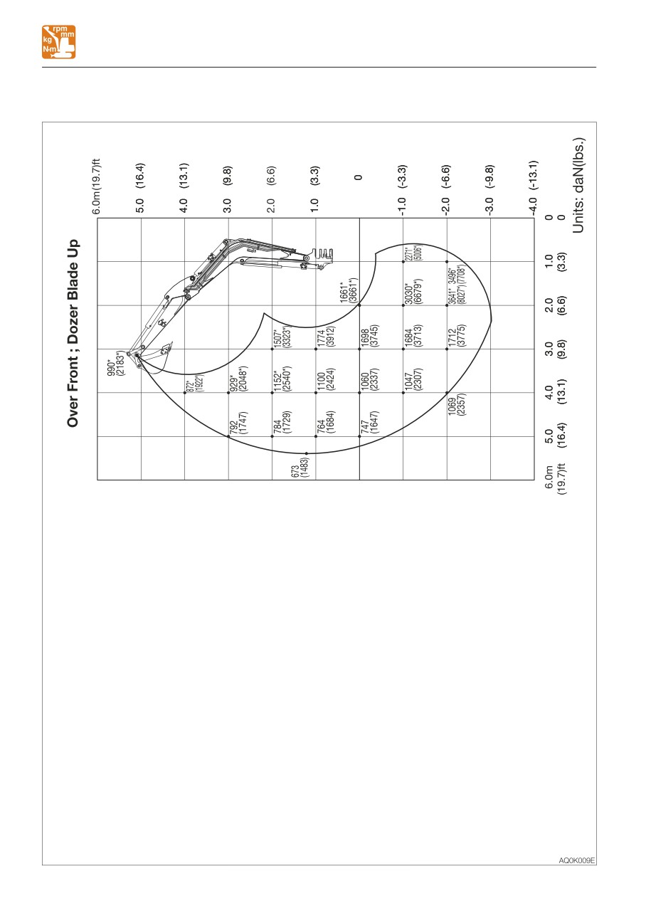
SPECIFICATIONS
LIFTING CAPACITIES
<Cab> Long arm (Applicable machine models 126100003 or later)
7-16