Takeuchi Hydraulic Excavator TB175W (S/N 17540001~). WORKSHOP MANUAL - page 16
 

  Index      Manuals     Takeuchi Hydraulic Excavator TB175W (S/N 17540001~). WORKSHOP MANUAL


Search            copyright infringement  


Content      ..     14      15      16      17     ..


Takeuchi Hydraulic Excavator TB175W (S/N 17540001~). WORKSHOP MANUAL - page 16


HYDRAULIC UNITS

CYLINDERS

IV-113

TB175W

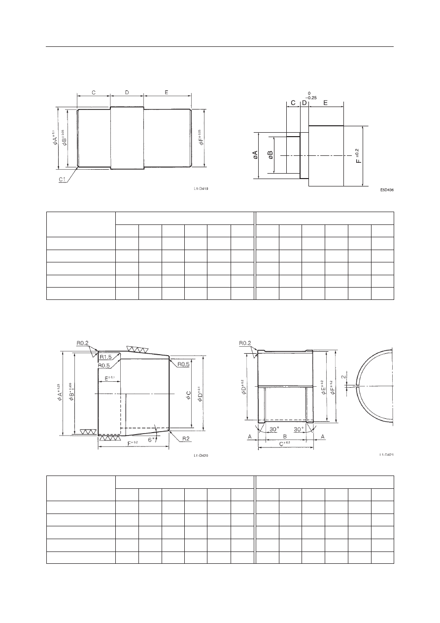
TABLE OF SPECIAL TOOLS

Installation Jig (B)

Installation Jig (A)

MATERIAL: SS41

MATERIAL: SS41

Unit: mm

Installation Jig (A)

Installation Jig (B)

A

79

69

59

59

79

Boom

Arm

Bucket

Boom Adjustment

Swing

B

75

65

55

55

75

C

43

43

32

32

43

D

12

12

12

12

12

E

75

75

46

46

75

F

75

65

55

55

75

A

89

79

59

89

89

B

74.5

64.5

49.5

74.5

74.5

C

10

10

10

10

10

D

5

5

5

5

5

E

30

30

30

30

30

F

95

90

70

95

95

Sliding Jig (C)

Fitting Jig (D)

MATERIAL: STKM13C

MATERIAL: NYLON

Unit: mm

Sliding Jig (C)

Fitting Jig (D)

A

121.0

101.0

85.7

90.7

121.0

Boom

Arm

Bucket

Boom Adjustment

Swing

B

119.7

99.7

84.7

89.7

119.7

C

101

84

70

75

101

D

107.3

90.7

75.7

80.7

107.3

E

23.5

22.5

19.5

19.5

23.5

F

97

77

75

75

97

A

13

10

10

10

13

B

71

57

55

55

71

C

97

77

75

75

97

D

110

95

80

85

110

E

117

99

84

89

117

F

120

102

87

92

120

HYDRAULIC UNITS

CYLINDERS

IV-114

TB175W

Corrective Jig (E)

Unit: mm

Boom

Arm

Bucket

Boom Adjustment

Swing

A

133

113

98

103

133

B

120

100

85

90

120

MATERIAL: STKM13C

HYDRAULIC UNITS

DOZER BLADE CYLINDER

IV-115

TB175W

DOZER BLADE CYLINDER

CONSTRUCTION

  1. Dust Seal
  2. Joint
  3. Guide Band
  4. O-ring
  5. Backup Ring
  6. Pipe
  7. Piston Rod

  8. Rod Cover
  9. Piston
10. Nut
11. Screw
12. Bearing
13. Ring

W2D409

12

13

11

1 2 8

5 4 3

7

6

9

10

HYDRAULIC UNITS

DOZER BLADE CYLINDER

IV-116

TB175W

HYDRAULIC UNITS

RAM LOCK CYLINDER

IV-117

TB175W

RAM LOCK CYLINDER

Contents

1.  Functional description
2.  Hydraulic connection plan
3.  Start-up and bleeding
4.  Fault-finding
5.  Repair instructions

1.

Functional description

Designed as plunger cylinder with integrated non-return valve.
The non-return valve is designed as an oil-tight round-seat valve which can be opened via a control piston.

Surface ratio

ψ


= 16:1

Control volume

1.4 cm

3

Control pressure

Pst = 30-50 bars

Blockable internal cylinder pressure

Pi= (Pst-4.5) 


ψ

  Example: 30 bar control pressure

Pi = (30-4.5) 

 16 = 408 bars

The control line is attached to the connecting line of both cylinders, i.e. the control pressure which can be applied to the
non-return valve in the cylinder head is also the initial pressure for the cylinder during reciprocating motion, i.e., only one
line is needed to the cylinder.

Note:

• The pressure in the tank line must be less than 2 bars when blockage occurs.
• The axle mounting should be level, hardened and greased (see Fig. 1).
• Larger stroke differences in the axle design should be avoided.
• Pay particular attention to the central position of the axle’s point of rotation in relation to the cylinders.
• The securing surfaces of the cylinder to the sub-assembly must be flat in order to avoid distorting the cylinder housing

when bolting together.

HYDRAULIC UNITS

RAM LOCK CYLINDER

IV-118

TB175W

Figs 1-6

2.

Hydraulic switching diagram

Fig. 2

HYDRAULIC UNITS

RAM LOCK CYLINDER

IV-119

TB175W

3.

Start-up and bleeding

At start-up, all components must be filled with oil and bled of air.

This is done as follows:

• Remove lock bolts from cylinder (pos. 10).
• Press rod down as far as bearing.

WARNING! Regardless of cylinder type, the check valve case projects fairly far into the oil filler bore. Be careful
not to damage the valve case when pressing down on the rod.

• The rod can also be pressed down hydraulically.
• Fill the cylinder area with oil and re-insert the lock bolts.
• To bleed both cylinders, undo the bleed screws at Pos. 11 and fill with oil until no more air comes out.
• Do up bleed screws but do not tighten. The screws should be easy to loosen.
• Apply control pressure to cylinder and tighten bleed screws until oil comes out without air bubbles. Bleeding is now

complete.

The entire bleeding operation should be carried out under clean conditions.

4.

Fault-finding

a) If the rigid axle fails to support a cylinder, the rod seal, Pos. 7, and the tightness of the check valve case, Pos. 3, should

be checked and the parts replaced if necessary.

b) If the axle cannot be brought to a variable position after switching off and on several times, the following should be

checked:

• At very high cylinder loads the internal cylinder pressure cannot be released (see Functional Description)
• The unit needs bleeding (see Start-up)
• If the operation of the axle is not rectified by bleeding, check whether there is adequate control pressure (see Functional

Description)

• If the previous points do not reveal any fault, the smooth operation of the control piston, Pos. 5, of the non-return valve

must also be checked (see Repair Instructions).

5.

Repair Instructions

a) Changing the rod seal

• Remove lock bolt, Pos. 10.
• Push down and remove rod, Pos. 2.

WARNING! Do not damage rod surface.

• Remove grooved ring using a round-edged tool.

WARNING! Do not damage the recess surface.

• Check scraper, Pos. 6, for damage and replace if necessary.
• Grease seals.
• Re-insert rod.

HYDRAULIC UNITS

RAM LOCK CYLINDER

IV-120

TB175W

Fig. 3

b) Demounting the non-return valve

• Remove cylinder bolts, Pos. 9.
• Remove cylinder, Pos. 4.
• Remove piston, Pos. 5. The piston should move freely in the non-return valve and in the cylinder.
• Remove non-return valve, Pos. 3, from the inside via the filler bore, Pos. 10.
• Check seals, Pos. 8, 14, 15, 16 and 17 for damage and replace if necessary.
• The non-return valve case cannot be dismounted any further.
• Reassemble components in reverse order above. Grease seals before assembly.
• Torque cylinder bolts, Pos. 9, to 16 Nm.

WARNING! Use only 12.9 Nm cylinder bolts.

Before start-up, bleed again as per Point 3 above.

WARNING! All checking and repair work should be carried out under clean conditions.

HYDRAULIC UNITS

RAM LOCK CYLINDER

IV-121

TB175W

Torque:

Pos.

MA (Nm)

9

10

11

12

16

180

10

40

Seal set

If part in Pos.

O-ring

∗∗

D

If part in Pos.

O-ring

D

Back-up ring

D

O-ring

D

O-ring

D

Lock bolt
Lock bolt
Lock bolt
Cylinder bolt
O-ring

D

Grooved ring

D

Scraper ring

D

Piston
Cylinder
Non-return valve case, complete
Rod
Cylinder housing
Name

D = be longing to seal set

D  0640.00.000

Supply separately only for seal set
410236

Supply separately only for seal set
410019
410391
410027
410401

310182
310180
310154
310200
410403
430079
440029

0620.00.003
0620.00.002
0620.01.000
0640.00.002
0640.00.001
Dwg no.

1

1

1
1
1
1

1
1
1
5
1
1
1

1
1
1
1
1

No.

10
18

3

17
16
15
14

12
11
10

9
8
7
6

5
4
3
2
1

Part

∗∗

HYDRAULIC UNITS

RAM LOCK CYLINDER

IV-122

TB175W

HYDRAULIC UNITS

SLEW MOTOR

IV-123

TB175W

  1. O-ring
  2. O-ring
  3. O-ring
  4. O-ring
  5. Friction Disc
  6. Cylinder Block
  7. Brake Piston
  8. Spring
  9. Shaft
10. Retainer

SLEW MOTOR

CONSTRUCTION

Hydraulic Motor

11. Spring
12. Retainer
13. Guide
14. Pin
15. Valve Plate
16. Bearing
17. Snap Ring
18. Collar
19. Shoe Holder
20. Pin

21. O-ring
22. Center Disc
23. Swash Plate
24. Bearing
25. Case
26. Pin
27. Piston
28. O-ring
29. Spring

L3D600

10

17

11

26

14

3

2

1

23

25

9

16

6

12
24

20
15

29

18

28

21

5

13 27 19

22

7

4

8

HYDRAULIC UNITS

SLEW MOTOR

IV-124

TB175W

  1. Plate
  2. Oil Seal
  3. Shaft
  4. Collar
  5. Bearing
  6. Case
  7. Bearing
  8. Plate
  9. Thrust Washer

Reduction Gears

10. Carrier 2
11. Plate
12. Race
13. Needle
14. Planetary Gear
15. Thrust Plate
16. Drive Gear
17. O-ring
18. Thrust Washer

19. Screw
20. Sun Gear
21. Carrier 1
22. Collar
23. Race
24. Needle
25. Planetary Gear A
26. Thrust Plate
27. Snap Ring

L3D601

26

16

13

14

12 18

10

7

6

2

3

4
1
8

5

11

22

20

27

19

15

21

9

25

17

23

24

HYDRAULIC UNITS

SLEW MOTOR

IV-125

TB175W

Brake Valve

  1. Cover
  2. Poppet
  3. O-ring
  4. Spring
  5. Housing
  6. Poppet
  7. Seat
  8. Seat
  9. Spring

10. Plug
11. O-ring
12. Piston
13. O-ring
14. Backup ring
15. Guide
16. O-ring
17. O-ring
18. Backup ring

19. O-ring
20. Backup ring
21. Body
22. Check Valve Assembly
23. Spring
24. Sleeve
25. Orifice
26. O-ring
27. Filter

28. Washer
29. Orifice
30. O-ring
31. Body
32. Spool
33. Spring
34. O-ring

L3D602

27

28

29 17 18

7

6

5 20 19 8

9

12 14 13 14 11

10

15

16

21

24

25

22

23

26

30

1

2

4

3

33

34

32

31

C

D

B

A

A: Relief Valve
B: Timer Valve
C: Check Valve
D: Anti-rebound Valve

HYDRAULIC UNITS

SLEW MOTOR

IV-126

TB175W

OPERATION

Hydraulic Motor

9 pistons (2) are fitted in the cylinder block (1) and
there is a valve plate (3) with two half moon ports, B
and C in the end. Also, the cylinder block (1) rotates
freely and is joined to the shaft (4) via the spline. On
the other band, the swash plate (5) is fastened to the
housing.
When high pressure oil is introduced into port B, one
piston (2) makes contact and force F bears on the
swash plate (5).
F = P 

×

 A  P: Pressure  A: Piston Sectional Area

The force F which the piston (2) applies to the swash
plate (5) is divided into force F1, which pushes the
plate, and force F2, which rotates the cylinder block
(1). The total sum of the components in the direction
of rotation of the high pressure side piston generates
a rotational force in the cylinder block (1) and via the
spline, torque is transmitted to the shaft (4), turning it.
Conversely, if high pressure oil is introduced to port
C, rotation is the reverse of the above.

Relief Valve
Operation 1

When the Motor is Started
When the motor is started, since the inertial load is
great, the pressure of the oil required to accelerate it
rises. If this pressure reaches the relief valve set
pressure, the relief valve operates and oil returns to
port M2.
In this way, the motor begins to turn as it relieves the
relief valve, and as the rotational speed increases, the
amount of relief decreases until it stops.
In this way, the shock during starting is absorbed.

When the Motor is Stopped
When the motor is stopped, the return circuit is closed
off.
However, since the motor tends to want to continue
rotating due to inertial energy, the pressure in port M2
rises. When this pressure reaches the relief valve’s set
pressure, the relief valve operates and oil flows to port
M1. In this way, the flow of oil to port M1 prevents
cavitation from occurring as it absorbs the shock
during stopping.

E5D603

3

5

A

F1

F

F

F

B

C

F2

F2

F2

4

2

1

M2

M1

T

E5D605

M2

M1

T

E5D606

HYDRAULIC UNITS

SLEW MOTOR

IV-127

TB175W

Operation 2

Since this relief valve has a shockless mechanism, it
operates in 2 steps.
1st Step
When relief valve operation starts, the pressure in
chamber B (P1) is kept at a pressure which is lower
than that in chamber C while the pressure in chamber
A (P) becomes higher than the pressure of the oil
flowing in.
At this time, there are two forces acting on the poppet
(10), force (F), which attempts to move the poppet
(10) to the left and force (F1) which pushes against the
seat on the right side. Since F = P 

×

 A, F1 = P1 

×

 A1,

P > P1 and A > A1, the poppet (10) is moved to the left
by this force “F – F1”.
This opens a supply side circuit from chamber A and
lets the pressure escape. That is, during the time piston
(11) is moving to its stroke end, the relief valve
operates at low pressure (about 1/3 the set pressure).

2nd Step
When the piston (11) reaches the stroke end, the
pressure in chamber B rises and the pressures in
chamber A and chamber B equalize. At this time, the
force moving the poppet (10) to the left side becomes
“P = P1”, so this becomes “A – A1” and the relief
valve operates at the specified set pressure.

Anti-rebound Valve

When the motor stops, this valve will connect the
motor main circuit to the makeup circuit for a pre-
scribed time to prevent motor rebound due to the
pressure in the main circuit.

When the Brake is Actuated
The braking pressure generated at the port Pv1 will
move the check valve (2) to the right until it is seated
at section B.

When the Motor Rebounds
When the motor is stopped by braking operation of the
brake valve, it starts to rebound due to the pressure in
the main circuit. This rebound pressure generated at
the port Pv2 will move the sleeve (3) to the left to open
the passage. This then releases the rebound pressure
to the port Cv.

G4D604

2

B

Pv1

Cv

Pv2

G4D605

Pv1

Cv

Pv2

B

3


A

10

B

P

P1

11

L3D604

HYDRAULIC UNITS

SLEW MOTOR

IV-128

TB175W

The rebound pressure also pushes the check valve (1)
to the left, which is the opposite direction of pushing
at the time of braking. The flux control valve built in
the check valve (2) (that is now on the lower pressure
side) releases the oil in the damper chamber (4) at a
constant flux. Therefore, the check valve (1) moves at
a constant speed. When the check valve reaches its
stroke end, the passage from the port Pv2 to the port
Cv is closed.

Timer Valve

This function is used to prevent sudden operation of
the parking brake when the motor is stopped.
At the time of parking brake operation, pressure oil
from the port P4 is supplied at all times to the port PG,
the valve spool (1) is pushed to the right by the force
of the spring (2), and the port PG is closed.
When turning pilot pressure or arm pilot pressure is
led to the port SH, the spool (1) is moved to the left
against the force of the spring (2), and the port PG is
opened. The pressure oil from the port PG passes
through the hole at the center of the spool (1) and is  led
to the parking brake release port (PB), so that the
parking brake is released.

When the pilot pressure at the port SH disappears, the
spool (1) is moved by the force of the spring (2) to the
right, the port PG is closed, and the oil in the brake
piston chamber (3) is prevented from escaping. The
oil in the chamber flows gradually through the orifice
(4) at the outer circumference of the spool (1) to the
drain port dr, so that the parking brake is not applied
rapidly, but after a certain time, just as if a timer were
used.

Parking Brake

The center discs (1) are connected to the housing and
the friction discs (2) are connected to the cylinder
block (3) via the spline, respectively. The center discs
(1) and friction discs (2) are pressed against the
housing (6) by the springs (4) via the brake piston (5).
The friction force between these discs generates the
brake torque to prevent the cylinder block (3) from
rotating.

When the pressure oil is introduced into the motor, the
oil flows from the parking brake release port (7) into
the brake piston chamber (8). The oil pressure over-

G4D606

Pv1

Cv

Pv2

1

2

4

1

2

PG

PB

SH

L3D605

1

2

4

3

PG

L3D606

6

5
4
3

2

1

L3D607


Content      ..     14      15      16      17     ..