Takeuchi Hydraulic Excavator TB175W (S/N 17540001~). WORKSHOP MANUAL - page 14
 

  Index      Manuals     Takeuchi Hydraulic Excavator TB175W (S/N 17540001~). WORKSHOP MANUAL


Search            copyright infringement  


Content      ..     12      13      14      15     ..


Takeuchi Hydraulic Excavator TB175W (S/N 17540001~). WORKSHOP MANUAL - page 14


HYDRAULIC UNITS

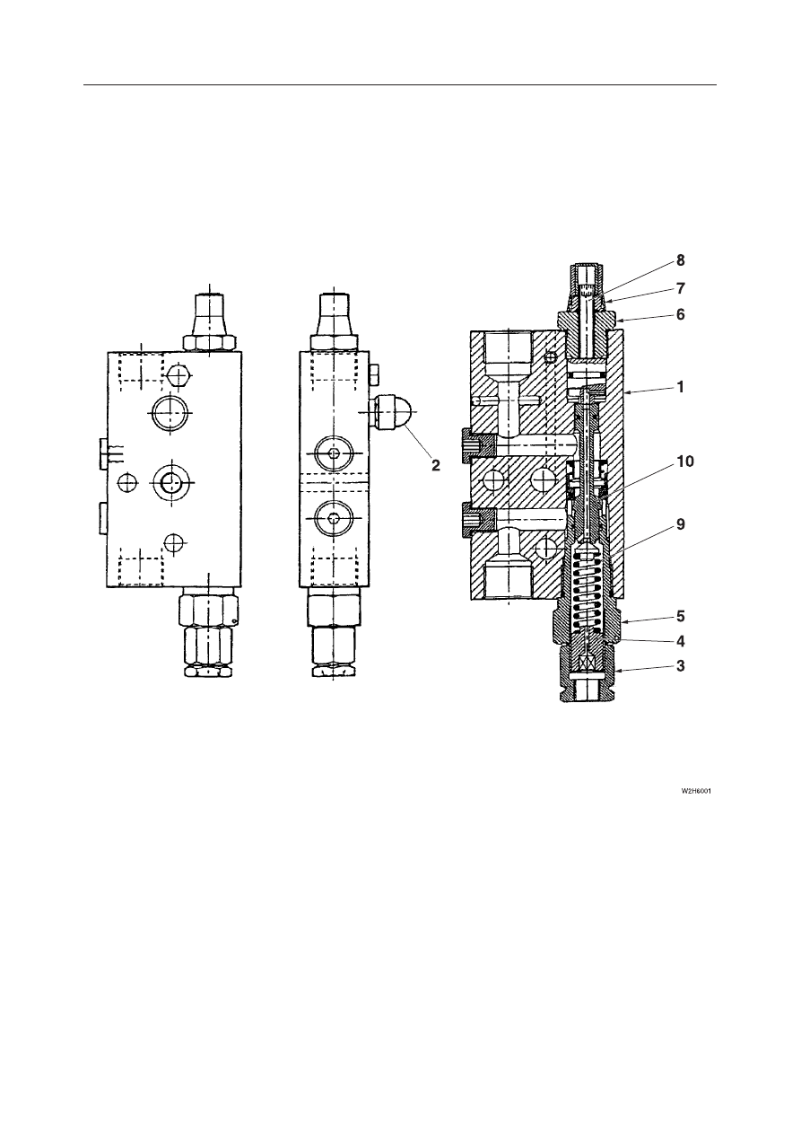
SHUT-OFF VALVES

IV-81

TB175W

  1. Body
  2. Relief Valve
  3. Plug
  4. Screw
  5. Plug

  6. Plug
  7. Lock Nut
  8. Adjusting Screw
  9. Spring
10. Spool

SHUT-OFF VALVES

CONSTRUCTION

HYDRAULIC UNITS

SHUT-OFF VALVES

IV-82

TB175W

OPERATION

The isolation valve prevents the boom or arm being
raised from falling. If the hydraulic hose breaks, the
valve blocks and isolates the hydraulic oil flowing to
the cylinder head.

When the boom or arm is raised, the pressure oil from
the hydraulic pump flows through the port V2 to push
up the check valve (1) and then through the port C2
into the boom or arm cylinder.

When the boom or arm is lowered, the pilot pressure
from the pilot valve (2) is led to the port PDB. The
pilot pressure in the port PDB moves the spool (3) to
the left. The return oil from the cylinder flows from
the port C2 to the passage through the spool (3) and
the check valve (1), the port V2 and into the tank
passage.

The boom or arm does not fall in case of hydraulic
hose breakage, because the oil flow leading to the
boom or arm is blocked and isolated in the passage
through the check valve (1) and the spool (3) if a hose
breaks.

HYDRAULIC UNITS

SHUT-OFF VALVES

IV-83

TB175W

INSPECTION AND ADJUSTMENT

Never adjust the adjuster screws on the isolation
valve. Otherwise, the valve may not work properly, or
the boom or arm may fall.

IV-8

3

HYDRAULIC UNITS

SHUT-OFF VALVES

IV-84

TB175W

IV-8

4

TROUBLE SHOOTING

When the hose of the boom or arm cylinders are
ruptured and the boom or arm falls, the emergency
shut-off valve is activated and stops the boom or arm
part way through the fall.

If the boom or arm drops and the emergency
shut-off valves are activated, immediately move
away from the suspended object.

If the engine can be started, the boom or arm can be
lowered with the operating lever. Check for safety,
then slowly lower the boom or arm.
If the engine cannot be started, the boom or arm can
be lowered using the procedure described below.

1. Check for safety in the working area and for

stability of the machine and lifted load.

2. Remove the cap (2).

3. Loosen the lock nut (3).

4. Tighten the stem (4) to lower the boom or arm.

5. Check for stability of the hoe attachment and

load.

6. Loosen the stem (4) secure it with the lock nut (3).

WARNING

HYDRAULIC UNITS

PILOT VALVE

IV-97

TB175W

PILOT VALVE

CONSTRUCTION

  1. Casing
  2. Plate
  3. Spool
  4. Plug
  5. Push Rod
  6. Push Rod
  7. Seal
  8. O-ring
  9. Spring Seat
10. Spring Seat

11. Washer 2
12. Spring
13. Spring
14. Spring
15. Spring
16. Joint
17. Disc
18. Adjusting Nut
19. Lock Nut

IV-

85

HYDRAULIC UNITS

PILOT VALVE

IV-87

TB175W

OPERATION

The pilot valve casing contains a vertical shaft hole

with a reducing valve incorporated into it. When the

handle  is  tilted,  the  push  rod  and  spring  seat  are

pushed down changing the secondary pressure spring’s

pressure.

The casing also contains an inlet port for hydraulic oil

port P (primary pressure) and an outlet port, port T

(tank) and secondary pressure is taken from 4 ports,

port 1, port 2, port 3 and port 4, on the bottom of the

vertical shaft hole.

When the Handle is in Neutral

In this case, the force of the secondary pressure setting

spring,  which  determines  the  pilot  valve’s  output

pressure (secondary pressure), is not transmitted to

the spool. Therefore, the spool is pushed up by the

return  spring  and  is  in  the  output  port  C  position

shown above, with oil not flowing between port P and

the output port C but flowing between the T port and

output port C.

When the Handle is Tilted

When  the  handle  (1)  is  tilted  and  the  push  rod  is

pushed, the spool moves downward and port P and

port A are joined. The oil in the pilot valve pump flows

out to port A, generating pressure.

a. When the pressure in port A is the same as the set

force of the spring (set pressure), there is a balance

between  the  hydraulic  pressure  and  the  spring

force.

b. When the pressure in port A is greater than the set

pressure, port A and port P close and port A and

port T open.

c. When the pressure at port A is lower than the set

pressure, port A and port P open and port A and port

T close.

In this way, the secondary pressure is kept constant.

IV-86

HYDRAULIC UNITS

PILOT VALVE

IV-98

TB175W

DISASSEMBLY AND ASSEMBLY

Table of Special Tools

General Cautions

• Since all parts in the pilot valve are precision

machined, carry out disassembly and reassembly
operations in a clean place and take special care not
to scratch the parts.

• Before disassembly, clean the outside surfaces of

the pilot valve.

• Clean each of the disassembled parts and apply

clean hydraulic oil to them.

NAME, DIMENSION

Q’ty

NAME, DIMENSION

Q’ty

1

2

INSTALLATION JIG (A)

INSTALLATION JIG (B)

• Replace all seals with new ones each time the pilot

valve is disassembled.

• During assembly, remove all the foreign matter

from each part and check them to make sure there
are no burrs, bruises using or other marks on them.
Remove all burrs and bruises using an oil stone.

• Apply thin coating of grease to seals when assem-

bling them.

Disassembly

1. Remove the lock nut and the adjust nut (1), then

remove the disc (2).
• Using copper or lead plates, fasten the valve in

a vise.

2. Remove the joint (3), then remove the plate (4).

• Use installation jigs (A) and (B).

MATERIAL A; S45C
MATERIAL B; SCM415N WITH CEMENTATION HARDENING

MATERIAL B; SCM415N WITH CEMENTATION HARDENING

IV-

87

HYDRAULIC UNITS

PILOT VALVE

IV-99

TB175W

3. Take out the plug (5) then remove the push rod (6)

from the plug (5).

If the plug is difficult to remove, use (–) screw

driver to remove it.

Be careful not to let the plug fly out from the

spring’s force.

4. Remove the O-ring (7) and seal (8) from the plug.

5. Remove the reducing valve (12) and spring (13).

Make match marks on the reducing valve and

casing hole so they can be placed in the same

position when they are reassembled.

6. Disassemble the reducing valve.

a. Push in the spring sheet (14) to contract the

spring (15), and move the spool (17) from the

small hole to the large hole of the spring sheet

(14).

Do not push in the spring sheet too far (at

most 6 mm).

IV-

88

HYDRAULIC UNITS

PILOT VALVE

IV-100

TB175W

b. Remove the spring seat (14), spring (15) and

washer 2 (16) from the spool (17).

Assembly

1. Assemble the reducing valve (12).

a. Install the washer 2 (16), spring (15) and spring

seat (14) on the spool (17).

b. Push in the spring sheet (14) to contract the

spring (15), and move the spool (17) from the

large hole to the small hole of the spring sheet

(14).

Do not push in the spring sheet too far (at

most 6 mm).

IV-

89

HYDRAULIC UNITS

PILOT VALVE

IV-101

TB175W

2. Install the spring (13) and reducing valve (12).

Install them in the positions they were in be-

fore disassembly.

3. Install the O-ring (7) and seal (8) in the plug (5).

4. Install the push rod (9) in the plug (5).

Apply hydraulic oil to the push rod.

5. Install the plug (5) and plate (4), then install the

joint.

Use installation jigs (A) and (B) to install the

joint.

Joint: 47.1 

±

2.9 N·m

IV-

90

HYDRAULIC UNITS

PILOT VALVE

IV-102

TB175W

6. Install the disc (2), the adjust nut (1) and the lock

nut.

Tighten the adjust nut to the point where all 4

push rods are uniformly making contact.

During  tightening,  the  disc  should  not  be

moved.

Adjust Nut: 68.6 

±

4.9 N·m

7. Apply grease to the contact surfaces of the joint

rotating portion, the disc and the push rod.

IV-

91

HYDRAULIC UNITS

PILOT VALVE

IV-94

TB175W

Replace

INSPECTION AND ADJUSTMENT

Checking the Parts

t

n

e

m

ta

e

r

T

ai

r

et

ir

C

 t

n

e

m

g

d

u

J

st

r

a

P

O-ring

⎯⎯

Seal
Seal Washer

⎯⎯
⎯⎯

Wear on sliding portions is 10 

μ

m or greater compared to non-

sliding portions

Scratches on sliding portions

Spool doesn’t move smoothly

Front end is worn 1 mm or more

Scratches in the sliding portion

Seal is imperfect due to damage

Tightening is loose at the pin, shaft or joint of the operating

portion, with looseness of 2 mm or greater

Due to wear, etc. tightening is loose at the pin, shaft or joint of

the operating portion, with looseness of 2 mm or greater

Scratches, rust or corrosion on the spool and sliding portion

Scratches, rust or corrosion on seal portions which come in

contact with the O-ring

Spool

Push Rod

Plug
Operating Portion

Casing,

Port Plate

Replace

Replace

Replace

Replace

Repair or replace

Replace

Replace

Repair or replace

Tighten to the speci-

fied torque

Replace

Replace

Repair or replace

IV-9

2

Secondary  pressure  doesn’t

rise

Primary pressure is insufficient

Spring  is  damaged  or  permanently

deformed

The clearance between the spool and

casing is abnormally large

There is looseness in the handle

Keep the primary pressure

Replace the spring

Replace the spool and casing assem-

bly

Disassemble and reassemble, or re-

place the handle

TROUBLESHOOTING

y

d

e

m

e

R

s

e

s

u

a

C

 e

l

b

a

b

o

r

P

m

o

t

p

m

y

S

Sliding parts are catching

Tank line pressure fluctuates

Air gets mixed into the piping

Repair or replace

Remove the abnormal portions of the

tank line

Operate  the  machine  several  times

and bleed out the air

Tank line pressure is high

Sliding parts are catching

Remove the abnormal portions of the

tank line

Repair or replace

Secondary  pressure  doesn’t

stabilize

Secondary pressure is high

HYDRAULIC UNITS

PILOT VALVE

IV-10

TB175W

PILOT VALVE (SWING)

CONSTRUCTION

  1. Casing

  2. Cover

  3. Plug

  4. Seal

  5. O-ring

  6. Push Rod

  7. Shim

  8. Spool

  9. Spring Seat

10. Washer

11. Spring

12. Spring

13. Shaft

14. Bushing

15. Cam

16. Ball

L3D350

16

6

4

3

2

5

9

12

11

7

10

8

1

13

15

14

IV

 3

IV-9

3

HYDRAULIC UNITS

PILOT VALVE

IV-104

TB175W

OPERATION

“IV-86”

DISASSEMBLY AND ASSEMBLY

General Cautions

“IV-87”

The following describes the disassembly procedure.

For assembly, refer to the construction diagram and

follow the disassembly procedure in the reverse or-

der.

Disassembly

1. Remove the boot from the cover.

Use a copper or iron sheet to fasten the valve to

the vice.

Apply grease to the cam and push rods.

2. Remove the set screw.

Set screw: 6.9 N·m

Apply Loctite #241 to the set screw.

3. Remove the cam pin, then remove the cam (1).

IV-9

4

HYDRAULIC UNITS

PILOT VALVE

IV-105

TB175W

4. Loosen the cap screws and remove the cover (2).

The cover and plug will rise from the surface if

the rebound spring is too strong, so loosen the

cap screws alternately so that the cover is flat.

Mark the cover and casing so that they can be

reassembled in the same positions.

Cap screw: 8.8 N·m

5. Remove the push rods (4) together with the plug

(5).

6. Remove the O-rings and seal (6) from the plug.

7. Remove the spool assembly (7) and spring (8)

from the casing.

Never disassemble the spool assembly as the

pressure has been adjusted by the shim.

L3D351

4

5

L3D352

6

IV-95

HYDRAULIC UNITS

PILOT VALVE

IV-9

6

TB175W

Replace

INSPECTION AND ADJUSTMENT

Checking the Parts

t

n

e

m

ta

e

r

T

ai

r

et

ir

C

 t

n

e

m

g

d

u

J

st

r

a

P

O-ring

⎯⎯

Seal
Seal Washer

⎯⎯
⎯⎯

Wear on sliding portions is 10 

μ

m or greater compared to non-

sliding portions

Scratches on sliding portions

Spool doesn’t move smoothly

Front end is worn 1 mm or more

Scratches in the sliding portion

Seal is imperfect due to damage

Tightening is loose at the pin, shaft or joint of the operating

portion, with looseness of 2 mm or greater

Due to wear, etc. tightening is loose at the pin, shaft or joint of

the operating portion, with looseness of 2 mm or greater

Scratches, rust or corrosion on the spool and sliding portion

Scratches, rust or corrosion on seal portions which come in

contact with the O-ring

Spool

Push Rod

Plug
Operating Portion

Casing,

Port Plate

Replace

Replace

Replace

Replace

Repair or replace

Replace

Replace

Repair or replace

Tighten to the speci-

fied torque

Replace

Replace

Repair or replace

IV-9

6


Content      ..     12      13      14      15     ..