Takeuchi Hydraulic Excavator TB175W (S/N 17540001~). WORKSHOP MANUAL - page 17
 

  Index      Manuals     Takeuchi Hydraulic Excavator TB175W (S/N 17540001~). WORKSHOP MANUAL


Search            copyright infringement  


Content      ..     15      16      17      18     ..


Takeuchi Hydraulic Excavator TB175W (S/N 17540001~). WORKSHOP MANUAL - page 17


HYDRAULIC UNITS

SLEW MOTOR

IV-129

TB175W

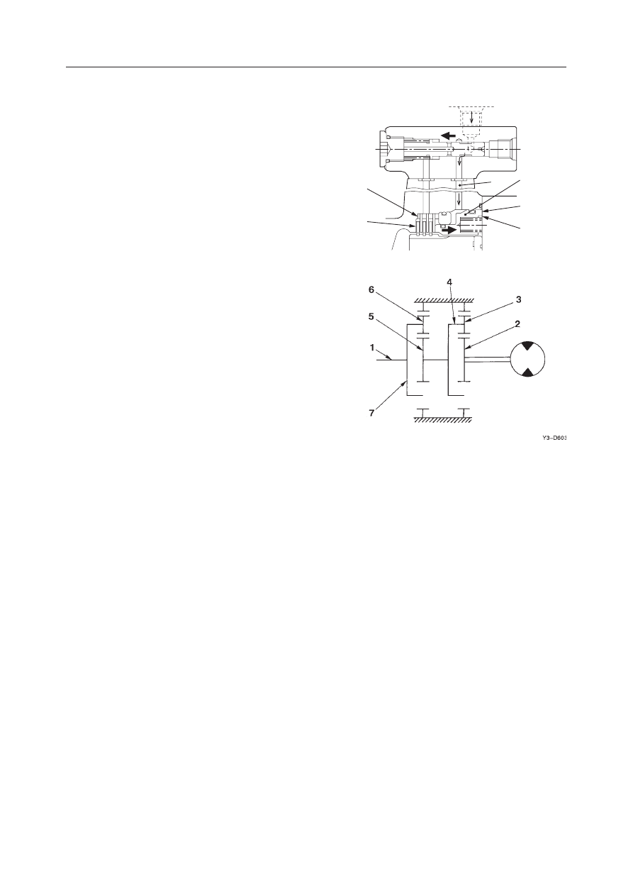
powers the spring force and moves the brake piston
(5) to the right. This generates a clearance between the
center discs (1) and friction discs (2) to release the
parking brake. When the motor stops, the spool re-
turns to the neutral position to close the parking brake
release port (7). The pressure oil in the brake piston
chamber (8) is introduced into the motor case and the
spring (4) operates the parking brake.

Reduction Gears

The reduction gear is composed of a 2-stage planetary
gear mechanism, and it converts the high-speed op-
eration of the motor to low speed torque for operation
of the pinion shaft (1).
In the figure on the right, the drive force transmitted
from the motor output shaft is transmitted to the
second stage sun gear (5) via the first stage drive gear
(2), the planetary gear (3) and the carrier 1 (4). Drive
force is transmitted in the same way to the pinion shaft
(1) via the second stage sun gear (5), the planetary
gear (6), and the carrier 2 (7), and this becomes the
slewing drive force.

L3D608

2

1

4

5

8

7

HYDRAULIC UNITS

SLEW MOTOR

IV-130

TB175W

DISASSEMBLY AND ASSEMBLY

Table of Special Tools

JIG (A)

NAME, DIMENSIONS

NAME, DIMENSIONS

JIG (C)

1

3

JIG (B)

JIG (D)

2

4

Unit: mm

General Cautions

• Carry out disassembly and assembly operations in

a clean place and provide clean containers to place
the disassembled parts in.

• Before disassembly, clean around the ports and

remove the paint from each joint using a wire
brush.

• Wash the disassembled parts and dry them with

compressed air. Do not use a rag, as this could
cause clogging of dirt.

• Make match marks on each part so that they will be

assembled in the same positions when reassembled.

• Replace all seals with new ones each time the unit

is disassembled, coating them lightly with grease.

• Check each part to make sure there is no abnormal

wear or seizing and use sandpaper, etc. to remove
any burrs, sharp edges, etc.

Disassembly
Slew Motor

1. Remove the cap screws and then the anti-rebound

valve.

K3D626

70

L3D609

¿30

¿45

50

¿35

¿47

L3D610

150

L3D611

¿95

-0.1 -0.2

63

100

40

10

100

L3D612

+0.2

0

¿63.2

+0.2

0

¿78.2

HYDRAULIC UNITS

SLEW MOTOR

IV-131

TB175W

2. Remove the cap screws to disassemble the motor

into the hydraulic motor (1) and the reduction
gear (2).
• Mark the mating position on both the hydraulic

motor and the reduction gear so that they can
be mated correctly when reassembling.

• Fix the hydraulic motor with a vise.

Brake Valve and Hydraulic Motor

1. Remove the cap screws and then the timer valve

(1).
• Be careful not to miss the O-ring.

2. Remove the cap screws and then the cover (2).

• Fix the hydraulic motor with a vise.
• Be careful not to let the valve plate drop off.

3. Remove the valve plate (3) from the cover.

K3D627

2

1

K3D629

2

L3D613

1

L3D614

3

HYDRAULIC UNITS

SLEW MOTOR

IV-132

TB175W

4. Remove the bearing (4).

5. Remove the orifice (5).

• The orifice is caulked. Do not remove it unless

necessary.

6. Remove the check valve.

a. Remove the plug (9).
b. Remove the spring (10) and check valve (11).

7. Remove the relief valve (12).

• Do not loosen the set screw nut (13).
• Do not disassemble the relief valve.

L3D615

4

L3D616

5

L3D617

9

10

11

9

10

11

L3D618

12

13

HYDRAULIC UNITS

SLEW MOTOR

IV-133

TB175W

8. Remove the brake piston (15).

• Blow the air from the brake release port PB

with care such that the brake piston does not
protrude.

9. Remove the collar (17).

10. Remove the cylinder block (18), friction discs

(19) and center discs (20).

11. Remove the shoe holder (14) and piston assembly

(21) from the cylinder block.

12. Remove the guide (22) and pins (23) from the

cylinder block.

L3D619

15

PB

PB

L3D620

17

L3D621

18

19

20

14

21

22

23

L3D622

HYDRAULIC UNITS

SLEW MOTOR

IV-134

TB175W

13. Remove the snap ring (24), retainer (25), spring

(26) and retainer (27) from the cylinder block
(18).
• Do not disassemble these parts unless neces-

sary.
These parts should be replaced as one assem-
bly.

14. Remove the swash plate (28).

15. Remove the shaft (29).

• Lightly tap the end face with a plastic hammer.

16. Remove the bearing (30) from the shaft (29).

• Do not disassemble these parts unless neces-

sary. The removed bearing cannot be used
again.

K3D643

29

30

E5D622

A

24

25

26

27

18

L3D623

28

A

L3D624

29

HYDRAULIC UNITS

SLEW MOTOR

IV-135

TB175W

17. Disassemble the timer valve.

• Be careful not to damage or deform the contact

surface.

a. Remove the plug (31).
b. Remove the spring (32) and spool (33).

• Use a pair of tweezers.

Reduction Gears

1. Remove the O-ring (1).

2. Remove the thrust plate (2).

3. Remove the drive gear (3).

4. Remove the planetary gear A (4), needles (5) and

inner race (6).

5. Remove the thrust washer (7).

6. Remove the carrier 1 (8).

7. Remove the sun gear (9).

8. Remove the carrier 2 assembly (10).

9. Loosen the screw and remove the thrust plate

(11).
• Loctite has been applied to the screw. Warm-

ing the screw screws (for example, using a
portable drier) will make its removal much
easier.

10. Remove the planetary gear B (12), needle (13),

inner race (14) and the thrust washer (15).

K3D644

33

32

31

L3D625

8

1

2

3

5

6

4

7

L3D626

9

10

L3D627

11

12

13

14

15

HYDRAULIC UNITS

SLEW MOTOR

IV-136

TB175W

11. Remove the collar (9) and plate (10).

• Do not disassemble these parts unless neces-

sary.
These parts should be replaced as one assem-
bly.

12. Remove the shaft (11) from the case.

• Be careful not to miss the shaft.
• If the shaft will not come out easily, lightly tap

it with a plastic hammer.

• To replace the taper roller bearing or collar, the

case assembly should be replaced.

13. Remove the inner race (24) of the taper roller

bearing.

14. Remove the oil seal (23).

• Use a flat blade screwdriver.
• The oil seal should be replaced with a new one

every time it is disassembled.

• Be careful not to damage the outer race of the

taper roller bearing.

L3D628

11

9

10

L3D629

25

11

24

L3D630

23

L3D631

HYDRAULIC UNITS

SLEW MOTOR

IV-137

TB175W

15. Remove the plug (25) from the case.

Anti-rebound Valve

1. Remove the plug (1) and then the spring (2).

2. Remove the check valve assembly (3).

3. Remove the sleeve (4).

4. Remove the plug (5) and then the orifice (6).

5. Remove the orifice (7), washer (8) and filter (9).

• The filter should be replaced with a new one

every time the anti-rebound valve is disas-
sembled.

G4D613

3

1

2

3

4

2

1

G4D614

6

5

G4D615

7

8

9

25

L3D632

HYDRAULIC UNITS

SLEW MOTOR

IV-138

TB175W

Assembly
Anti-rebound Valve

1. Mount the filter (9), washer (8) and orifice (7) on

the body.
• Use a new filter.

Orifice: 4.9 N·m

2. Mount the orifice (6) on the body.

Orifice: 2.45 N·m

3. Fit the O-ring to the plug (5), and mount them on

the body.

Plug: 61.8 N·m

4. Mount the sleeve (4) on the body.

5. Mount the check valve assembly (3) and the

spring (2) on the body.

6. Fit the O-ring to the plug (1), and mount them on

the body.

Plug: 61.8 N·m

Brake Valve and Hydraulic Motor

1. Assemble the timer valve.

• Be careful not to damage the rotation section of

the valve.

a. Mount the spool (33) and spring (32) on the

body.

b. Fit the O-ring to the plug (31) and mount them

on the body.

Plug: 39.2 

±

2.0 N·m

G4D615

7

8

9

G4D614

6

5

G4D613

3

1

2

3

4

2

1

K3D644

33

32

31

HYDRAULIC UNITS

SLEW MOTOR

IV-139

TB175W

2. Mount the retainer (27), spring (26), retainer (25)

and snap ring (24) on the cylinder block (18).
• To mount the snap ring, push the retainer (25)

by using the press and jig (C).

• Position the retainer (27) so that its tapered

side (A) faces the cylinder block.

3. Fit the pins (23) to the cylinder block.

• Apply grease to the pins.

4. Mount the guide (22).

5. Fit the shoe holder (14) to the piston assembly

(21) and mount them on the cylinder block.
• Apply the hydraulic oil to the rotation section.

6. Insert the bearing (30) into the shaft (29).

• Insert the bearing by using the press and jig

(A).

7. Install the shaft (29) in the housing.

• Lightly tap with a plastic hammer to install.

K3D643

29

30

E5D622

A

24

25

26

27

18

14

21

22

23

L3D622

L3D633

29

HYDRAULIC UNITS

SLEW MOTOR

IV-140

TB175W

8. Install the switch plate (28) in the housing.

• Apply grease to the side (A) of the swash plate.

9. Install the cylinder block (18) in the housing.

• Be careful not to let the shoe holder or other

parts drop off.

• Use the press to insert.

10. Mount the center discs (20) and the friction discs

(19).
• Total number of friction discs: 2
• Total number of center discs: 3
• Be careful of the mounting order.

11. Fit the O-ring to the collar (17) and insert them in

the housing.

12. Fit the O-ring to the brake piston (15) and insert

them in the housing.
• Use the press to insert.
• Make sure that the pin hole (A) of 8.5 mm in

diameter is positioned as shown in this figure.

L3D623

28

A

L3D621

18

19

20

L3D620

17

L3D634

15

A

22.5¡

HYDRAULIC UNITS

SLEW MOTOR

IV-141

TB175W

13. Install twelve large springs (16), eight small

springs (17), and the O-ring.
• Make sure that the eight small springs (17) are

positioned as shown in this figure.

14. Fit the O-rings and backup rings to the relief valve

(12).

15. Mount the relief valve assembly on the cover.

• Be careful not to let the spring jump out.

Plug: 37 

±

20 N·m

• Do not loosen the lock nut (13).

16. Mount the check valve.

a. Mount the spring (10) and poppet (11) on the

cover.

b. Fit the O-ring to the plug (9) and mount them

on the cover.

Plug: 157 

±

10 N·m

17. Insert the bearing (4) into the cover.

• Use the jig (B) and the press to insert.

17

17 16

L3D635

L3D618

12

13

L3D617

9

10

11

9

10

11

L3D615

4

HYDRAULIC UNITS

SLEW MOTOR

IV-142

TB175W

18. Fit the pin to the cover.

19. Mount the orifice (5) on the cover.

• Caulk the circumference of the orifice female

screw by using a punch.

20. Mount the pin and valve plate (3) on the cover.

• Apply grease on the back of the valve plate (the

side facing the cover) in advance to prevent the
plate from dropping off.

• Upon mounting the pin, caulk the position (A)

using the punch as shown in this figure.

21. Mount the cover (2) on the case and fix them with

the cap screws.
• Be careful not to let the valve plate drop off.

Cap screw: 127 

±

10 N·m

22. Mount the timer valve (1).

a. Fit the O-ring to the case.
b. Mount the timer valve and fix it with the screw.

Screw: 39.2 

±

2.0 N·m

L3D636

4

5

L3D637

3

6mm

A

K3D629

2

L3D613

1

HYDRAULIC UNITS

SLEW MOTOR

IV-143

TB175W

Reduction Gears

1. Insert the oil seal (23) into the case.

• Use the jig (C) and the press to insert.
• The oil seal diameter (A) after insertion should

be 4.25 mm.

2. Put grease into the inner race of the taper roller

bearing.
• Grease type: Shell ALVANIA Grease
• Grease volume: 80~90 mL

3. Mount the shaft (11) and plug (25) on the case.

• The shaft (11) should be mounted before mount-

ing the plug (25).

Plug: 15.7 

±

0.8 N·m

4. Mount the plate (10) and collar (9).

• Mount the collar while loading the 11770 N on

the inner race using the jig (D).

E5D629

L3D629

25

11

L3D628

11

9

10

23

L3D638

A

HYDRAULIC UNITS

SLEW MOTOR

IV-144

TB175W

5. Mount the thrust washer (15), inner race (14),

needles (13) and planetary gear B (12) on the
carrier 2 (10).

6. Mount the thrust plate (11) on the carrier 2 (10)

and fix them with the cap screws.
• Apply Loctite #242 to the cap screws.

Cap screw: 24.5 

±

4.9 N·m

7. Mount the carrier 2 (10) on the case.

8. Fit the snap ring on the sun gear (9).

L3D639

14

13

12

15

10

L3D627

11

12

13

14

15

L3D640

10

L3D641

9


Content      ..     15      16      17      18     ..