SANY Crawler Hydraulic Excavator SY195C9, SY205C9, SY215C9, SY225C9. Service Manual - page 40
 

  Index      Manuals     SANY Crawler Hydraulic Excavator SY195C9, SY205C9, SY215C9, SY225C9. Service Manual (2013)


Search            copyright infringement  


Content      ..     38      39      40      41     ..


SANY Crawler Hydraulic Excavator SY195C9, SY205C9, SY215C9, SY225C9. Service Manual - page 40


8-143

Disassembly and Assembly

7. After adjustment is 

fi

 nished, 

fl

 ush the front

window glass and check if any water leaks
into the cab.

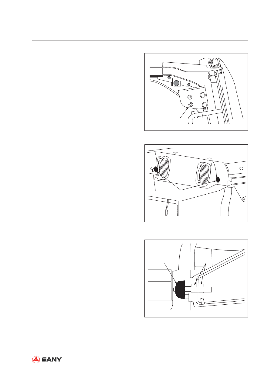
8. Adjust the "locked" position of the lock of

front window assembly

1) After the "locked" position of the lock of

front window assembly is adjusted in
Step 6 and Step 7, raise the assembly
to the roof.

2) Set the locks of the front window as-

sembly at the rear of the cab at the
"locked" position, and check the follow-
ing items:

Check the conditions of left lock (16)
and right lock (17).

The front window assembly must con-
tact the left and right rubber stopper
(18), and the rubber stoppers must be
pushed backward by 1.5 – 3.0 mm.

The front window assembly shall push
the limit switch 4 – 7mm backward.

16

19

ZX215-1006272

19

18

ZX215-1006273

18

20

ZX215-1006274

8-144

Disassembly and Assembly

3) Close  the front window assembly (10).

4) Loosen the retaining nut (20) at the left

and right side of rubber stopper (18),
and pull the two rubber stoppers (18)
inward so that they can not contact the
"unlocked" front window assembly.

5) Adjust the position of latch bolt (21).

Latch bolt(21): M10, Inner diameter of
plate (23): ø14.5 mm

6) Adjustment of left and right rubber stop-

per (18)

Allow front window assembly (10) to
contact the left and right rubber stopper
(18). (when the lock is "unlocked")

7) Lock front window assembly (10).

8) Turn the left/right rubber stopper (18) to

the left by one and a half round.

Turning the rubber stopper (18) leftward
for one round is equivalent to pressing
it by 1.5 mm.

When front window assembly is "un-
locked", it must move the left/right rub-
ber stopper (18) by 1.5 – 3.0 mm.

9) Tighten the retaining nuts (20) at both

sides of the rubber stopper (18).

23

22

21

ZX215-1006275

10

18

ZX215-1006277

18

ZX215-1006278

8-145

Disassembly and Assembly

9. Adjust the front window assembly retainer

(24).

Adjust and lock both sides of the retain-
er (24) so that surface (d) of stopper
(D) of front window assembly contacts
surface (c) of retainer (24) when front
window assembly is raised.

10. Check the locking ability of front window

assembly.

After the adjustment from Step 6 to
Step 9 is finished, check the locking
force of left lock (16) and right lock (17).

Check the locking force at the "locked"
side (front of cab) and the "unlocked"
side (rear of cab).

 Left lower pin:

27 – 34 N·m {2.75 – 3.47 kgf·m}

 Mounting bolt: 

Adhesive(LT-2) 

17

16

ZX215-1006271

10

24

D

ZX215-1006279

24

c

D

d

8-146

Disassembly and Assembly

8.34  Monitor - Remove and Install

1. Unscrew the three bolts (4). Remove the

mounting plate and the monitor assembly
from the bracket (3).

2. Remove the nut (1) and the gasket (2) to

separate the monitor (5) from the mounting
plate.

1

2

3

4

5

ZX215-1006281

8.34.1 Removal

8.34.2 Installation

Installation is to be performed in the re-
verse order of removal.


CAUTION

Disconnect fi rst the cable connecting to
the negative (-) post of the battery.

8-147

Disassembly and Assembly

8.35  Controller AS - Remove and Install

1. Remove the fuse box (1) and storage box

(2).

2. Remove rear covering (3).

3. Remove air conditioner cover (4).

4. Remove the controller wiring connectors

A1(5) and A2(6).

5. Remove the four bolts. Remove the con-

troller assembly (7).

ZXT335-1006800

1

4

2

3

8.35.1 Removal

8.35.2 Installation

Installation is to be performed in the re-
verse order of removal.


CAUTION

Disconnect fi rst the cable connecting to
the negative (-) post of the battery.

ZX215-1308283

7

6

5

8-148

Disassembly and Assembly

8.36 Radio

8.36.1 Structure

1. Main structure

2. Wiring

ZX215-1006284

ZX215-1006285

BACK PANEL

POWER, GROUND AND AUDIO OUTPUT

AUDIO INPUT

RED — L. SOUND TRACK INPUT

RADIO ANTENNA

WHITE — R. SOUND TRACK INPUT

RED — ACC IGNITION

YELLOW — BATT POWER SUPPLY

BLACK — GROUND

GRAY — R. SOUND TRACK OUTPUT

 +

 — R. SOUND TRACK OUTPUT –

WHITE — L. SOUND TRACK OUTPUT +

BLACK — L. SOUND TRACK OUTPUT –

8-149

Disassembly and Assembly

1. Remove the console cover.

2. Remove the radio connector CN-003F.

3. Remove the four screws and the washers

in order to remove the radio and the radio
mounting brackets from the console cover.

4. Remove the four screws and the washers

in order to remove the radio from the radio
mounting brackets.

8.36.2 Removal

ZX215-1006286

Radio

Arm rest cover

ZX215-1006287

Connector CN-003F  Cab harness

ZX215-1006288

Radio

Mounting bracket

Washer

Screw

Arm rest

NOTICE

Disconnect the power supply prior to
removal.

8-150

Disassembly and Assembly

8.36.3 Installation

Installation is to be performed in the re-
verse order of removal.

8.36.4  Connector model and wiring

1

2

3

4

6

7

5

1

2

3

20b

R+

L+

28

0

R-

L-

4

6

7

5

ZX215-1006289

Harness socket terminals

Type: Yasaki 7119-3070

Raido wiring terminals

8-151

Disassembly and Assembly

8.37 Battery

8.37.1 Structure

1)

Spinning 

post

2)

Charge 

densiometer

3)

Heat-sealing 

cover

4)

PP 

casing

5)

Central polar ear

6)

Forged 

grid

7)

Paste (active material)

8)

"Bag-type" 

screen

9)

Polar 

group

10) Liquid-gas separator
11) Central busbar

ZX215-1006290

J

C

H

G

I

E

B

D

F

1

2

10

3

4

5

6

A

7

8

11

9

8-152

Disassembly and Assembly

8.37.2 Removal

ܡ 㓈 ᡸ

㪘 ⬉ ∴

0$,17(1$1*()5((%$77(5<

VAR

TA

ZX215-1006291

Bolt

Terminal

Grounding cable

Battery

1. Removal of battery grounding wire

Open the tarpaulin, unscrew the bolt, and
remove the terminal from the battery wiring
post.

2. Disconnect the battery wiring cable and the

battery breaker cable.

VAR

TA

VARTA

ZX215-1006292

Battery cable

Battery

Breaker cable

3. Remove the four bolts and washers. Re-

move the battery assembly from the bot-
tom plate. Remove the battery.

VA

R

TA

ZX215-1006293

VA

R

TA

Battery

Bolt

Wahser Battery box

NOTICE

Turn the start switch to the OFF posi-
tion before removal.

Do not remove the charge densimeter.
Tighten the densimeter clockwise, if it
is loosened, with a suitable tool.


CAUTION

Battery gas can cause explosion. No
sparks or flames are allowed near the
battery.

8-153

Disassembly and Assembly

8.37.3 Installation

Installation is to be performed in the re-
verse order of removal.

8.37.4 Replacement

There are two 12V batteries with ground-
ing negative (-) posts in the machine.  If one 
battery fails in the 24V system, it must be re-
placed with one of the same type. Batteries of 
different types are probably charged at differ-
ent speeds, which may cause one of them to 
fail due to overloading. 

NOTICE

During installation, apply vaseline to
battery terminals in order to prevent
corrosion.

8-154

Disassembly and Assembly

8.38 Start Switch

8.38.1 Structure 

12

3

45

6

25,24

23

22

20

18

17

15

13

12,11

28

6

10,9,8,7

21

27

1

14

19

16

26

5

4,3,2

ZX215-1006294

1)

Housing

2)

Key

3)

Ring

4)

Knob

5)

Nut

6)

Cylinder

7)

Cap

8)

Shield

9)

Pin

10) Spring
11) Disc
12) Spring
13) Plug
14) Rotor

15) Cover
16) Spring
17) Ball
18) Spring
19) Contact SPR-B
20) Contact A
21) Seat

22) Contact SPR-A
23) Contact B
24) Terminal
25) Bolt
26) O-ring seal
27) Harness AS
28) Washer

8-155

Disassembly and Assembly

8.38.2 Removal

1. Remove the setscrew to remove the con-

sole cover.

2. Remove both setscrews in order to remove

the mounting plate and the start switch
from the console cover.

3. Remove the nut so as to remove the start

switch from its mounting plate.

ZX215-1006295

0$;

0,1

67$57

21

2))

/2&.

Start swich

Console cover

Set screw

ZX215-1006296

Mounting plate Start switch

Set screw Console cover

ZX215-1006297

Start switch

Mounting plate

Nut

NOTICE

Disconnect the power supply of the
start switch before removal.

8-156

Disassembly and Assembly

Working principle and wiring of start switch

1. Working principle

2. Wiring

Key Position

ON/OFF

Battery (B)

Battery Relay (BR)

Accessory

Preheat Plug

Start Relay (C)

(R1)

(R2)

HEAT

OFF

ON

START

3

6

ACC

BR

B

1

4

R1

R2

C

3

6

13

22

1

4

16

11

ZX215-1006299

KEY SWITCH WIRING TERMINALS
JACKET MODEL

˖

YAZAKI 7222-7464-30

HARNESS PLUG TERMINALS

JACKET MODEL

˖

YAZAKI 7123-7464-30

8-157

Disassembly and Assembly

8.39 Fuse Box

8.39.1 Removal

1. Remove the cover.

2. Remove the bolts and take off the back

cover along with the fuse box.

3. Remove the bolts so as to separate the

fuse box and harness assembly from the
back cover.

ZX215-1006300

Cover

ZX215-1006301

Back cover

Bolt

Fuse box cover

ZX215-1006302

Bolt

Back cover

Fuse box harness

8-158

Disassembly and Assembly

8.40 Wiper

8.40.1 Structure

ZX215-1006303

Rotating mechanism

Wiper motor

Blade

Arm

Mounting bracket

Connector

8.40.2 Working principle

ZX215-1006304

M

YELLOW (RESET)

GREEN (LOW SPEED)

BLUE (HIGH SPEED)

RED (POWER+)

BLACK (POWER-)


Content      ..     38      39      40      41     ..