SANY Crawler Hydraulic Excavator SY195C9, SY205C9, SY215C9, SY225C9. Service Manual - page 39
 

  Index      Manuals     SANY Crawler Hydraulic Excavator SY195C9, SY205C9, SY215C9, SY225C9. Service Manual (2013)


Search            copyright infringement  


Content      ..     37      38      39      40     ..


SANY Crawler Hydraulic Excavator SY195C9, SY205C9, SY215C9, SY225C9. Service Manual - page 39


8-127

Disassembly and Assembly

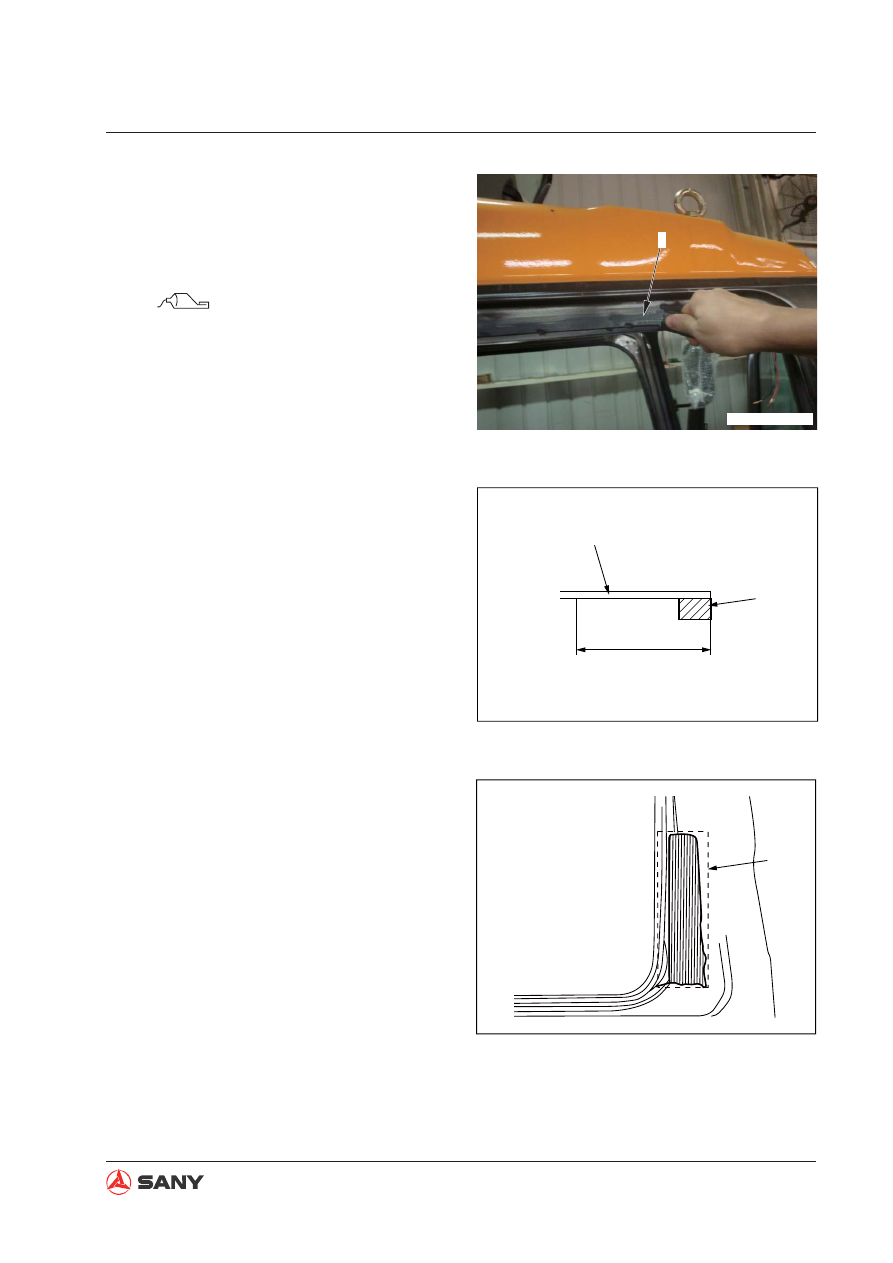
3) Apply priming paint (for painted sur-

face) evenly onto the surface where
sealing rubber is to be adhered and
where adhesive agent is to be applied
(on the cab (8)).

 Priming paint (for painted sur-

face): Sunrise MSI Primer 24

Do not apply primer more than twice;
otherwise, the performance of the prim-
er will be reduced.

Applying location: Cover the whole area
of (a). Dimension of (a): 25mm

Besides the above locations, apply
primer also onto the right window glass
and the cab door lower window glass.

Additional priming area on the right
window glass: (b)

Additional priming area on the cab
door lower window glass: (c)

8

ZXT215-1006231

ZX215-1006232

8

6

a

b

ZX215-1006233

8-128

Disassembly and Assembly

Dry the primer for at least 5 minutes
(within 8 hours).

Do not use wrong priming paint.

If, for example, glass primer is mistak-
enly used, wash it with unleaded gaso-
line.

4) Apply priming paint (for glass surface)

onto the contact surface of window
glass (9).

 Glass primer:

Sunrise MSI Primer 35

Do not apply the primer more than
twice; otherwise, the performance of
the primer will be reduced.

Priming area: Apply the priming paint
on the contact surface of glass (9)
(rubber seal (6)adhering location) and
along cab frame (8).

Leave a 5 mm margin uncoated along
the black strip adjacent to the clear
area of the glass.

When priming paint has been coated,
dry it for at least 5 minutes (within 8
hours).

Do not use wrong primer.

If wrong glass primer is used, wash it
with unleaded gasoline.

c

ZX215-1006234

9

ZX215-1006235

8

6

9

d

ZX215-1006236

8-129

Disassembly and Assembly

4. Adhere rubber seal (6) (with adhesive tape

on both sides) along the inner edge of the
contact surface of the glass.

Do not detach the  waxed paper on the
rubber seal before the window glass is
installed.

Do not touch the cleaned area on the
glass before rubber seal is adhered.

Be careful not to allow the rubber seal
on the corners to peel off.

When sticking rubber seal (6) along the
window frame, do not overlap the two
ends of the seal. A 5 mm gap between
the two ends of the seal is recommend-
ed.

1) Stick rubber seal (6) onto the right cab

window frame as illustrated.

Adhere additional rubber seal (6a) onto
the right cab window

Position of the additional rubber seal:

(f): 50 mm

(g): 90 mm

(h): 250 mm

6

ZXT225-1006245

6

e

ZXT225-1006246

f

h

g

6a

ZXT225-1006247

8-130

Disassembly and Assembly

2) Adhere rubber seal (6) on the left cab

window as illustrated.

3) Adhere rubber seal (6) onto the lower

cab door window as illustrated.

Adhere additional rubber seal (6b) onto
the lower cab door window frame as il-
lustrated.

Position of additional rubber seal:

(j): 110 mm

(k): 90 mm

(m): 200 mm

6

ZXT225-1006248

6

ZXT225-1006249

j

m

k

6b

ZXT225-1006250

8-131

Disassembly and Assembly

4) Adhere rubber seal (6) onto the front

window glass as illustrated.

Different from the rubber seal (6) on
other window, rubber seal (6c) on the
bottom of the front window shall be
adhered onto the external edge of the
lower part of the front window frame.
(If it is adhered along the inner edge,
the rubber seal will be seen through the
clear part of the glass.)

5. Positioning of new window glass

1) Check the clearance between the edge

of glass and the cab in 4 directions,
and position the glass. Make sure the
clearance is even.

2) Put a tape [6] across the glass (9) and

cab (8) and draw a line (n) on it for
alignment.

Adhere tape [6] at 3 points as illustrated
for precise alignment of right window
glass, left rear window glass and cab
door lower window glass.

3) Cut the tapes across the glass (9) and

the cab (8) and remove the glass.

Do not remove the tape on the left side
of the glass until the glass is installed.

6

ZX215-1006243

6

6c

ZXT225-1006252

8

9

[6]

n

ZXT215-1006245

8-132

Disassembly and Assembly

When positioning front window glass
(4), cover it across the width of the win-
dow frame in the horizontal direction.

Set the clearance (p) between the top
edge of the glass and the upper frame
at 3 mm when positioning it in the verti-
cal direction.

[6]

[6]

[6]

8

9

ZX215-1006246

P

4

ZX225-1006255

8-133

Disassembly and Assembly

6. Adhesive

Store adhesion agent in dark places
where temperature is blow 25°C.

Do not heat the adhesive to above
30°C.

Before using adhesive that has been
unsealed, remove the hardened part at
the nozzle.

1) Open the aluminum seal (13) on the

head of the cylinder (12) and install the
nozzle (14).

 Adhesive:

Sunrise MSI SR sealant U90 4463876

2) Cut the tip of nozzle (14) as illustrated.

Dimension of the cut:

(q): 10 mm

(r): 5 mm

3) Set the cylinder (12) in the gun [7].

An electrical caulking gun is more ef-

fi

 cient.

13

12

ZX215-1006247

q

r

14

12

[7]

ZX215-1006249

8-134

Disassembly and Assembly

4) Remove the waxed paper of the rubber

seal on the surface where adhesive is
to be applied.

5) Apply adhesive (15) along the external

edge of the rubber seal (6).

Adhesive (15) for rubber seal (6) on
cab (8) shall be applied  as illustrated:

Dimension of (s): 10 mm

Dimension of (t): 15 mm

Adhesive (15) shall be thicker that the
rubber seal (6).

Apply adhesive of the same thickness
evenly.

6

15

ZX215-1006250

s

8

t

6

15

ZX215-1006251

8-135

Disassembly and Assembly

Apply adhesive (15) onto the additional
rubber seal of the right window (6a) and
additional rubber seal of the cab door
lower window (6b).

7. Install window glass

1) Install window glass (9) and align it with

the mark on the cab. (See step 5)

Since the glass can not be remove
once installed, be very careful when
performing this task.

Install the glass properly within 5 min-
utes after adhesive has been applied.

2) Press the perimeter of the glass (9)

after is has been put in place until it is
securely stuck to the rubber seal.

Press the corners of the glass hard.

6a

15

ZX215-1006252

15

6b

ZX215-1006253

9

ZXT215-1006254

8-136

Disassembly and Assembly

After the front window glass has been
installed, 

fi

 ll the clearance  between the

glass on area (s) and the center adjust-
ing seal (16) to the dimension of (t) and
(u). Coat primer onto glass (4) on sec-
tion A-A and apply the adhesive as 

fi

 ll-

ers.

Dimension of (t): 2 mm

Dimension of (u): 5 mm

Use a rubber spatula to cover the edge
of the glass and trim the adhesive.

Remove surplus adhesive.

 Glass primer:

Sunrise MSI Primer 35

 Adhesive:

Sunrise MSI SR Sealant U90 4463876

8. Fix the glass

1) After the right window glass (1) has

been adhered to the cab, put position-
ing chips a (1 or 2 pcs) beneath the
glass in order to 

fi

 x it.

4

t

A-A

16

u

A

A

S

ZX215-1006255

1

a

ZXT215-1006256

8-137

Disassembly and Assembly

2) Use foam polystyrene blocks [9] and

rubber band [10] to fix the glass and
the rubber seal as illustrated.

9. After the glass has been 

fi

 xed, remove all

the remaining primer and adhesive on the
cab and on the glass.

Clean the adhesive with unleaded gas-
oline before it is hardened.

Do not apply impacting force onto the
glass when cleaning it.

10. Protection  of 

fi

 xed window glass

1) Remove the positioning chips, foam

polystyrene blocks and the rubber band
after 10 hours.

(Condition: Temperature: 20; humidity:
60%)

2) Wait for another 14 hours after the re-

moval of positioning chips, foam poly-
styrene blocks and rubber band before
operating the machine.

[9]

[10]

ZX215-1006257

8-138

Disassembly and Assembly

8.33  

Front Window AS - Disassemble and Assemble

8.33.1 Disassemble

1. Raise the front window assembly to the

roof and secure it with the rear locks (at
both sides).

2. Remove left corner plate (1) and right cor-

ner plate (2).

Mounting bolt (4) and washer (3) of the
left corner plate will be used in Step 6
to hang the pull rod.

3. Release the rear lock of the cab.

4. Lower the front window assembly carefully

a bit. Take out and hold the rollers (5) and
(6) at the bottom of the front window from
the removed parts in Step 2.

5. Remove roller (5) and (6) from both sides

of the bottom of the front window.

The front window assembly must be removed 
from the cab in order to replace the front win-
dow glass. 

4 3

1

2

ZX215-1006258

6

5

ZX215-1006259

NOTICE

Before removing the front window as-
sembly, lower the work equipment onto
the ground and shut down the engine.

8-139

Disassembly and Assembly

6.  Remove  pin  (7)  at  the  lower  left  side.

Plate (8) at the end of the pull rod (9)
will come out by removing of pin (7).

Hang plate (8) onto the mounting bolt
of left corner plate (using the washer)
and 

fi

 x it.

7. Pull out the front window assembly (10)

from the opened part of the guide rail and
lower the assembly gradually.

6

7

8

9

ZX215-1006260

9

8

ZX215-1006261

10

ZX215-1006262

NOTICE

A return load of 58.8 N {6 kg} is applied
onto the rear of the cab. Be very care-
ful when removing pin (7) to disconnect
pull rod (9).

Disassembly and Assembly

9. Move the front window assembly (10) to

the right and the left and remove the two
upper rollers (11) and (12) from the guide
rail. Then, remove the front window as-
sembly (10).

8. Lower the front window assembly (10)

completely.

Be careful not to allow the front window
assembly to damage the machine mon-
itor.

10

ZX215-1006263

10

12

11

ZX215-1006265

8-141

Disassembly and Assembly

8.33.2 Assemble

Reverse the disassembling sequence.

Adjust the opening and closing of the front
window assembly as per the following in-
struction.

1. Open and close the front window assembly

and check if it interferes with the guide rail.
Check if the roller is jammed.

2. If the front window can not be opened or

closed properly, loosen the mounting bolt
of the roller adjusting bracket (13) and
adjust the condition of the front window.
Tighten the mounting bolt after adjusting.

 Mounting bolt: 

34.3 N·m {3.5 kgf·m}

3. Raise the front window assemble and 

fi

 x it

with rear locks (at both sides).

Check if the locks at the rear of the cab
are securely 

fi

 xed.

4. Install the right corner plate (2).

After the "locked" position is adjusted in
Step 6, tighten the corner plate.

Install the right corner plate. Clearance
(a) between the guide rail and the right
corner plate (2) is 0 – 2.0 mm.

Install the right corner plate. Keep the
surface (R) of the roller without a level
error.

13

ZX215-1006266

a

a

2

ZX215-1006267

R

ZX215-1006268

8-142

Disassembly and Assembly

5. Install left corner plate (1)

After the "locked" position is adjusted in
Step 6, tighten the corner plate.

Install left corner plate. Clearance (b)
between the guide rail and the left cor-
ner plate (1) is 0 – 2.0 mm.

Install left corner plate and keep the
surface (R) of the roller without a level
error. (See previous illustration).

6. Adjust the "locked" position of the lock of

front window assembly as per the following
instruction.

1) Tighten the left corner plate (1) and  the

right corner plate (2) in a nearly correct
position so that front window glass (14)
is pressed closely against the adjusting
seal (15) on the cab.

2) Open and close the front window as-

sembly and check the working condi-
tion of left lock (16) and right lock (17).

If left lock (16) and right lock (17) do
not work properly, Loosen the mounting
bolt (19) of the lock and move the lock
(16) forward. Tighten the bolt after that.

Adjust the right lock with the same
method.

3) Check again the adaptability between

the front window assembly (14) and
the adjusting seal (15) on the cab.
(Checked in Step 1)

Tighten the mounting bolts of the left

and right corner plates when the left 
and right locks (16, 17) are properly in 
place.

b

b

1

ZX215-1006269

15

14

ZX215-1006270

17

16

ZX215-1006271


Content      ..     37      38      39      40     ..