SANY Crawler Hydraulic Excavator SY195C9, SY205C9, SY215C9, SY225C9. Service Manual - page 38
 

  Index      Manuals     SANY Crawler Hydraulic Excavator SY195C9, SY205C9, SY215C9, SY225C9. Service Manual (2013)


Search            copyright infringement  


Content      ..     36      37      38      39     ..


SANY Crawler Hydraulic Excavator SY195C9, SY205C9, SY215C9, SY225C9. Service Manual - page 38


8-111

Disassembly and Assembly

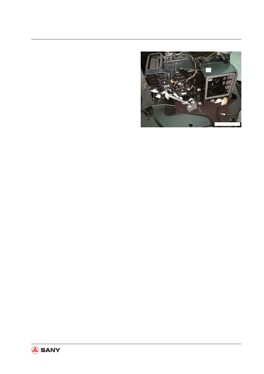
23

ZX215T-1006201

17. Remove the air conditioner unit (23).

NOTE: Also disconnect the two hoses con-
necting to the bottom of the air conditioner
when removing the air conditioner unit.

8-112

Disassembly and Assembly

8.29.2 Installation

Installation is to be performed in the re-
verse order of removal.

NOTE: Apply compressor oil (ND8#) to the 
threads of the parts connected with the re-
frigerant lines. Tighten the line connections 
with a double-end spanner. 

 Screw (hose clamp): 

8.83~14.7 N·m {0.9~1.5 kgf·m}

 Bolt (pressure plate): 

13.5±1.2 N·m {1.38±0.12 kgf·m}

Refrigerant charging

Charge refrigerant (HFC-134a) into the air
condition return lines with tool (S).

For more information, see “Refrigerant” on
page 4-141.

NOTICE

Keep the hoses free from contamination
by dirt, dust or water while installing the
return hose of the air conditioner.

Make sure that the O-ring seal is pres-
ent in the connection before connecting
a hose of the air conditioner.

Make sure that the O-ring seals are free
from any damage or deformation.

8-113

Disassembly and Assembly

8.30  

Counterweight AS - Remove and Install

8.30.1 Removal

1. Remove the cover (1) from the counter-

weight. Install eyebolts to the counter-
weight. Hold the counterweight.

2. Remove the four bolts (2).

1

ZX225-1106004

ZX225-1106005

2

Wire rope

ZX225-1106006

3

3. Lift the counterweight levelly with wire rope

or chain hoist.

NOTE: Be careful not to damage the
engine, radiator or cooler.

 Counterweight assembly: 

3901 kg

8-114

Disassembly and Assembly

8.30.2 Installation

Installation is to be performed in the re-
verse order of removal.

 Threads (mounting bolt - counter-

weight):

Thread adhesive (Tonsun 1277)

 Mounting bolt (counterweight):

1,180~1,470 N·m {120~150 kgf·m}

Counterweight adjustment

1. Move the counterweight with a crane to a

suitable position on the frame.

2. Push the counterweight and install the

bolts. Adjust the position of the counter-
weight in such a manner that the following
dimensions can be obtained.

Clearance with swivel:

10±5 mm(L&R)

Clearance with bodywork door:

10±5 mm(L&R)

Step from swivel in left to right direction

b: max. 5 mm

Step from bodywork door in left to right
direction

a: 10±4

Step from bodywork top cover in upper
to lower direction

c: max. 5 mm


b=0±5mm

a=10±4mm

c=0±5mm

ZX215-1006205

Door

Counterweight

Swivel

8-115

Disassembly and Assembly

8.31  Cab AS - Remove and Install

1. Remove the 

fl

 oor mat (1).

2. Remove the fuse box (2) and storage box

(3).

3. Remove outer covering (4).

4. Remove the air conditioner cover (5).

2

5

3

4

ZX215T-1006001

8.31.1 Removal


CAUTION

Disconnect fi rst the cable connecting to
the negative (-) post of the battery.

5. Disconnect the left wire harness (6), moni-

tor harness connector (7) and window
washer harness (8).

6. Remove the right side air duct (9).

7]’

6

8

9

ZXT225-1006216

1

ZX215T-1006193

8-116

Disassembly and Assembly

7. Remove external air 

fi

 lter (10).

10

ZXT225-1006217

8. Disconnect the external air duct (11).

11

ZX215T-1006210

9. Remove the storage box on the armrest

(12).

12

ZX215T-1006211

8-117

Disassembly and Assembly

10. Remove the radio connector (13).

11. Remove the radio wire harness (14).

13

14

ZX215T-1006212

12. Remove the window washer reservoir (15).

15

ZX215T-1006213

13. Remove the window washer pipe (16).

16

ZX215T-1006214

8-118

Disassembly and Assembly

14. Remove the decor cover (17).

17

ZX215T-1006215

15. Remove the four mounting nuts (18) and

the 

fi

 ve mounting bolts (19).

20

ZX215T-1006217

16. Lift the cab assembly (20) for removal.

  Cab assembly: 450 kg

19

18

ZXT225-1006224

8-119

Disassembly and Assembly

8.31.2 Installation

Installation is to be performed in the re-
verse order of removal.

 Bolt: 200 N·m {20.4 kgf·m}

 Nut: 210 N·m {21.4 kgf·m}

8-120

Disassembly and Assembly

8.32  Cab Window Glass – Disassemble and Assemble

1)  Right window glass
2)  Front window glass
3)  Lower front glass
4)  Cab door window glass (upper)
5)  Cab door window glass (lower)
6)  Cab door window glass (upper)

7)  Left side rear window glass
8)  Rear window glass
9)  Roof window glass
10)  Rubber sealing strip
11)  Center adjusting seal
12)  Front window AS (Glass and frame)


Cab window glasses (1), (2), (5), (7) and (9) are adhered to the window frame. 


When replacing front window glass (2), disassemble front window assembly (12). (If the cab 
is install with a front window assembly, do not only replace the front window glass.) For more 
information about front window replacement, see “Front Window AS - Disassemble and As-
semble” on page 8-134.

1

3

4

5

6

7

8

9

2

10 11

10

10

10

10

12

ZX215-1006218

8-121

Disassembly and Assembly

8.32.1 Removal

1. Removal of glass (3)

Glass (3) is hold in place by sealing strips. 
Pull it upward carefully to remove it. 

2. Removal of glass (4) and (6)

1) Remove the sealing strip from the

frame of the cab door.

2) Push the glass outward carefully from

inside of the cab and remove glass (4)
and (6) together with the frame.

NOTE: To avoid 

fi

 nger cut during when remov-

ing a shattered or cracked glass, cover it with 
a piece of adhesive 

fi

 lm or tapes.

3

ZX215-1006219

4

6

ZX215-1006220


CAUTION

Removing shattered or cracked window
glass may cause fi nger cuts.

Wear proper PPEs when removing shat-
tered cab window glasses.

8-122

Disassembly and Assembly

3) Remove glass (4) and (6) from the

frame with a screw driver.

3. Removal of glass (8)

1) Remove the retainer from the groove

on the rubber with an ordinary screw
driver.

2) Put a thin bamboo chip inside part A of

the retaining rubber and detach the re-
tainer along the edge.

3) Pat the glass from inside of the cab

and remove it. This job may require two
people.

6

4

ZX215-1006221

Frame

Seal

8

ZX215-1006222

A

A

ZX225-1006231

Rubber retainer side

Glass

Retainer

Rubber retainer

Cab side

Cab

8-123

Disassembly and Assembly

4. Removal of glass (1), (2), (5), (7) and (9).

1) Remove the resin board, decor strip

and retainer along the edge of the
glass.

2) Punch a hole through the adhesive with

a drill (or a cutter) as illustrated.

3) Pull a piece of piano string (or steel

wire) through the hole as illustrated.

1

2

5

7

9

ZX215-1006223

ZX215-1006224

Adhesive

Glass

Cab

Drill

ZX215-1006225

Piano string
(or steel wire)

8-124

Disassembly and Assembly

4) Fix both ends of the piano string onto

two screw drivers. Pull the wire back
and forth in order to cut the adhesive
and detach the glass from the cab. This
job may require 2-3 people.

Run the string along the center of the
adhesive. The string may break when
it becomes very hot. Use different sec-
tions of the string while cutting the ad-
hesive.

ZX215-1006226

Cab

Glass

(Outside)

(Inside)

Adhesive

8-125

Disassembly and Assembly

8.32.2 Installation

Reverse the disassembling sequence
when installing glasses (3), (4), (6) and
(8). Follow the procedures below to install
glasses (1), (2), (5), (7) and (9).

1. Clean the remaining adhesive and rubber

on cab frame (contact surface) with a knife
or scraper [5].

Remove the remaining adhesive and
rubber so that they will not affect the
application of new adhesive. Do not
scrape the original paint on the surface.
(Scraping of paint reduces the perfor-
mance of the adhesive.)

2. Clean the grease, dust and dirt on the cab

(8) and the glass (9) with unleaded gaso-
line.

Contaminant on the contact surface re-
duces the performance of adhesive.

Clean the black part on the back of the
glass.

After cleaning, dry the glass for at least
5 minutes.

[5]

ZXT215-1006227

8

ZXT215-1006228

9

ZXT215-1006229

8-126

Disassembly and Assembly

3. Priming coat (10)

Priming paint expires 4 months after
production. Do not use expired paint.

Use the paint within 2 hours after it is
unsealed.

Use the paint within 24 hours even if it
is sealed again immediately after un-
sealing. (Dispose the paint 24 hours
after it is unsealed)

1) Make sure the adhesive paint and glass

priming paint are well agitated before
application.

If the priming paint is stored in a refrig-
erator, keep it under ambient tempera-
ture for at least half a day before agita-
tion.

(If the paint is unsealed immediately af-
ter it is taken out of a refrigerator, water
will condense on it.)

2) Always wash a used brush (11) with

unleaded gasoline before using it.

Check the brush for contaminants after
it has been washed.

Prepare two brushes for priming paint,
one for painted surface and the other
for glass surface.

10

11

ZX215-1006230

Old adhesive edge
on cab side

Cab


Content      ..     36      37      38      39     ..