SANY Crawler Hydraulic Excavator SY195C9, SY205C9, SY215C9, SY225C9. Service Manual - page 21
 

  Index      Manuals     SANY Crawler Hydraulic Excavator SY195C9, SY205C9, SY215C9, SY225C9. Service Manual (2013)


Search            copyright infringement  


Content      ..     19      20      21      22     ..


SANY Crawler Hydraulic Excavator SY195C9, SY205C9, SY215C9, SY225C9. Service Manual - page 21


6-8

Testing and Adjusting

6.3  

Valve Clearance - Adjust

Service Standard  (Unit: mm)

Location

Service Item

Standard Value

Limits

Remedy

Valve clearance (engine cold)

0.4

Adjust

Special Tools

Symbol

Tool Name and Shape

Part Number

Application

Flat head screwdriver

MH060008

Valve clearance adjustment

(Carried on vehicle)

Check and adjust valve clearance in cold state  
as per the following procedure:

6.3.1 Testing

1. Remove the rocker arm cover.

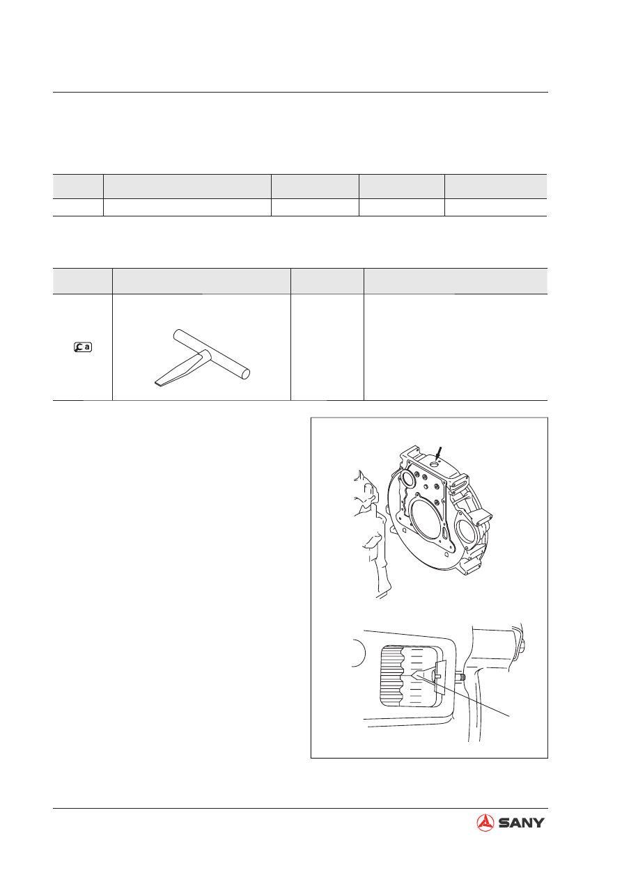
2. Turn the No.1 piston or the No.6 piston to

the top dead center of compression stroke
by following the procedure below.

Turn the engine until the mark 16 on
the flywheel aligns with the pointer on
sight glass of the 

fl

 ywheel shell.

Turn the No.1 piston or the No.6 piston
to the top dead center of compression
stroke.

ZX215-1004009

1

6

Sight Glass

Sight Glass

Pointer

6-9

Testing and Adjusting

Cylinder

1

2

3

4

5

6

INT

EXH

3. When the No.1 piston is at the top dead

center, adjust the valve clearance in a se-
quence marked by the black dot.

1) When a feeler gauge is used for such

measurement, resistance to a moving
feeler gauge in the clearance should be
felt.

2) If the feeler gauge moves easily in the

clearance, it is impossible to obtain ac-
curate result.

4. If the measured value is out of specifica-

tion, readjustment shall be performed ac-
cording to the following method.

NOTE: 

When the rocker arm at the intake side and 
rocker arm at the exhaust side cannot be 
turned with hands, it is indicated that the pis-
ton has reached the top dead center of com-
pression stroke. Turning the engine by one 
more turn, the top dead center of compression 
stroke of No.1 piston and No.6 piston inter-
changes. 

ZX215-1004007

Valve clearance

6-10

Testing and Adjusting

6.3.2 Adjusting

1. To adjust valve clearance, loosen the lock-

nut before adjusting the adjustment screw.
Standard clearance is achieved when re-
sistance to the feeler gauge is felt when
pulling it out from the clearance.

2. After adjustment, stop the turning motion

of the adjustment screw with a screwdriver,
and tighten the locknut.

  Locknut: 16-24 N·m {1.7±2.5 kgf·m}

3. Go on with the next step until all valve

clearances marked with a black dot have
been adjusted.

4. Check the clearances again with the feeler

gauge. Readjustment should be made if
the value is out of speci

fi

 cation.

5. When the engine is carried in vehicle, us-

ing 

 to turn the adjustment screw will

make your work easy.

ZX215-1004006

Valve Clearance

Adjustment Screw

Locknut

ZX215-1004008

Adjustment 
Screw

Testing and Adjusting

6.4  Compression Pressure - Measure

Service Standard

Location

Service Item

Standard Value

Limits

Remedy

Compression 

pressure

Each cylinder (at 200 

rpm)

2550kPa {26kgf/cm²}

1960 kPa {20kgf/cm²}

Test

Differential pressure 

between cylinders

Below 390 kPa {4kgf/cm²}

Test

Special Tool 

Symbol

Tool Name and Shape

Part Number

Application

Compression 

pressure gauge 

connector

A

M14×1.5

A

MH061460

Measuring compression 

pressure

1. Reduction of compression pressure can be

an indication for engine overhaul.

2. Check the compression pressure regularly

and pay attention to its variation from time
to time. In addition, in a new vehicle or
when new parts are installed for replace-
ment, the pressure may be higher due to
running-in of the piston ring, valve seat,
etc. The pressure will become normal as
the parts wear.

3. Before testing, make sure engine oil, start

motor and battery are in normal condition.

4. Set the machine as per the following:

1) Preheat the engine until engine coolant

temperature reaches 75~85°C.

2) Switch off all lamps and auxiliary de-

vices.

3) Place the gear lever in a neutral posi-

tion.

5. Remove the entire fuel injector.

6-12

Testing and Adjusting

6. Cover the fuel injector mounting opening

with cloth.

7. Activate the start motor in order to run the

engine. Check if the cloth is stained by for-
eign substances.

8. Determine the problem with the engine ac-

cording to the substances (engine oil and/
or coolant) on the cloth.

1) When engine oil is found, it might be

improper sealing caused by piston ring.
Check the piston ring.

2) When engine oil and coolant are found,

it might be cracking of cylinder. Replace
the crankcase.

9. Mount the gasket and tool 

 to the fuel

injector mounting hole and fix them with
the injector cap. Install the compression
pressure gauge.

10. Start the engine and measure the com-

pression pressure of each cylinder. Calcu-
late the differential pressure between the
cylinders.

11. When the compression pressure and the

differential pressure between cylinders de-
viate from their limits, inject a small amount
of engine oil through the fuel injector
mounting hole, and measure the compres-
sion pressure again.

If the compression pressure is higher,
it is probably due to worn or damaged
piston ring or cylinder inner surface.

If the compression pressure is still low,

it is probably due to stuck valve or im-
proper seating, or improperly mounted 
gasket of cylinder head. 

ZX215-1004005

Rags

Injector

mounting hole


CAUTION

When coolant and/or engine oil is found 
attached to the cloth, running the engine 
may cause the hot coolant and engine oil 
to squirt out through the mounting hole of 
the fuel injector. This is very dangerous. 
Never touch or look into the fuel injector 
mounting hole when the engine is running. 

Testing and Adjusting

6.5  

Fuel Injection Timing - Test and Adjust

Service Standard

Location

Service Item

Standard Value

Limits

Remedy

Fuel injection timing (BTDC)

14°

Adjust

Tightening Torque (Unit: N·m)

Symbol

Parts Tightened

Tightening Torque

Remark

Union nut

24

Lock plate

3.4~4.9

Lock seat - delivery valve

39~44

Nut (used for mounting fuel injection pump)

29~39

Special Tool 

Symbol

Tool Name and Shape

Part Number

Application

Universal Exten-

sion Rod

A

14

A

MH061099

Testing and adjusting the 

fuel injection timing

6.5.1 Testing

1. Remove the injection pipe, lock plate, lock

seat, retainer ring and delivery valve from
the No.1 cylinder of the fuel injection pump.

2. After removal of all the parts, install the

lock seat.

NOTE: The removed parts should be put
into light oil in order to keep them free from
dust.

ZX215-1004011

Lockplate

Injection pipe

 Lock Seat

Retainer Ring

Spring

Delivery Valve

6-14

Testing and Adjusting

3. Install the prepared injection pipe onto

No.1 cylinder. Keep the other end of the in-
jection pipe downward so that fuel 

fl

 owing

out can be observed.

4. Turn the crankshaft manually over 180° in

the forward direction to locate No.1 cylin-
der in a position that is about 30° from the
top dead center of compression stroke.

7. Make sure that the flywheel mark and

pointer are one degree before the fuel in-
jection timing.

ZX215-1004013

Injection pipe

Positioning Lever

Priming pump

ZX215-1004012

Injection pipe

ZX215-1004014

Pointer

5. The main pump is used to transfer fuel. As

the fuel 

fl

 ows out of the injection pipe, turn

the engine manually in the forward direc-
tion.

NOTE: The engine positioning lever on the
governor must be placed in the starting
position.

6. When the fuel coming out of the injection

pipe is about to stop, continue to turn the
engine slowly until the fuel stops coming
out.

6-15

Testing and Adjusting

6.5.2 Adjusting

1. Loosen the mounting nuts of fuel injection

pump.

A: 4 nuts (on the 

fl

 ange)

B: 1 nut

2. Targeted at the pointer, activate the injec-

tion pump in order to adjust injection tim-
ing.

3. Tighten the nuts to specific torque. Mea-

sure the injection timing again.

NOTE: When the fuel injection timing deviates 
from its standard value, the following steps 
must be followed for adjustment. 

ZX215-1004015

A

B

ZX215-1004016

Injection Pump

Pointer

6-16

Testing and Adjusting

4. When the injection timing is slow, move the

injection pump toward the crankcase (di-
rection C).

5. When the injection timing is fast, move the

injection pump away from the crankcase
(direction D).

6. When injection timing meets the standard

value, install the delivery valve, spring, re-
tainer ring, lock seat, lock plate and injec-
tion pipe.

7. Tighten all the parts to speci

fi

 c torques.

ZX215-1004017

D

C

Injection Pump

ZX215-1004018

Injection pipe

Lock Seat

Lockplate

6-17

Testing and Adjusting

6.6  Engine Oil Pressure - Measure

Service Standard

Location

Service Item

Standard Value

Limits

Engine oil pressure at 

70~90°C

Min. speed, unloaded

145 KPa

49 KPa

Max. speed, unloaded

295 KPa~490 KPa

195 KPa

Tightening Torque (Unit: N·m)

Symbol

Part Tightened

Tightening Torque

Remark

Engine oil pressure switch

7.8~12

Engine cold

Lubricant/Sealant

Symbol

Location

Part Number

Amount

Threads of pressure switch

A420300000032

As necessary

1. Remove the engine oil pressure switch.

ZX215-1004019

Engine Oil 
Pressure Switch

2. Mount the adaptor to where the engine oil

pressure switch has been removed. Mount
the engine oil pressure gauge to the adap-
tor.

ZX215-1004020

Pressure Gauge

Adaptor

6-18

Testing and Adjusting

3. Preheat the engine until engine oil temper-

ature reaches 70-90°C.

4. Measure respectively the unloaded engine

oil pressure at minimum speed and maxi-
mum speed.

5. If the measured value is lower than the

speci

fi

 ed standard value, check the entire

lubrication system.

6. After measuring, apply sealant to the

threads of pressure switch. Tighten the
pressure switch to speci

fi

 c torque.

NOTICE

Then engine oil pressure switch must be 
installed when the engine is cold. 

Testing and Adjusting

6.7  Engine Speed Sensor - Adjust

NOTE: Remove the engine speed sensor (1) 
before adjusting. Check for presence of metal 
chips and for damaged sensor top. Restore 
the sensor. 

1. Screw on the sensor (1) until its end con-

tacts with ring gear tip (2) of the 

fl

 ywheel.

2. Unscrew the sensor some degrees.

Degrees:  1.2~1.4 turns

Adjust the clearance (a) between the
sensor end and the 

fl

 ywheel edge to 2±0.2

mm.

3. Tighten the sensor (1) with the nut (3).

 Nut: 49.0~68.6 N·m {5~7kg·m}

4. Make sure that the engine speed is dis-

played properly on the control panel after
adjustment.

ZX215-1004021

2

1

3

a

ZXT215-1004001

1

6-20

Testing and Adjusting

6.8  A/C Compressor Belt Tension  - Test and Adjust

ZX215-1004022

A

Drive Pulley

Compressor Belt 
Pulley

6.8.1 Testing 

Press the intermediate point of the belt be-
tween the drive pulley and the compressor pul-
ley with a 

fi

 nger force of about 58.8 N

(

6kgf

)

and measure de

fl

 ection (A) of the belt, which 

shall be 5

~

8 mm (0.20 in

~

0.31in). 

6.8.2 Adjusting

NOTE: If the belt de

fl

 ection is abnormal, adjust 

it according to the following procedure.

1. Loosen the bolts (1) and (2).

2. Move the compressor (3) and the bracket

(4) together to adjust belt tension.

3. After positioning the compressor (3), tight-

en the bolts (1) and (2).

4. Check belt tension again after adjustment.

1

2

3

4

ZXT215-1004002

6-21

Testing and Adjusting

NOTE: 

Check each belt for damage. Check the
V-groove and the V-belt for wear. In addi-
tion, it is especially important to keep the
V-belt free from friction with bottom of the
V-groove.

Contact local Sany dealer and replace the
belt in case of the following conditions.

The fan belt has been stretched and
little margin is left for adjustment.

Cuts or cracks are found in the belt.

Abnormal sliding or noise.

When a new belt is mounted, readjust the
belt tension after one hour operation.

Reference

Use a tensiometer to check the compressor 
belt tension. 

New Belt

Used Belt

637±108 N

{65±11 kgf}

441±88.2 N

{45±9 kgf}

6-22

Testing and Adjusting

6.9  Swing Bearing Clearance - Measure

Measuring tool

Symbol 

Part Number

Part Name

H 60033930

Dial 

gauge

The following steps are to be followed
when measuring the clearance of swing
bearing.

1. Fix the dial gauge (H) to the track frame

and apply the probe to the lower end of the
outer race.

2. Place the work equipment to the maxi-

mum reach position.  Raise the bucket to
a height that the bucket tips and the swivel
table bottom are on the same level.

At the moment, the front of upper structure
lowers while the rear rises.

3. Set the dial gauge (H) to zero.

4. Set the arm almost perpendicular to the

ground and lower the boom until the front
track shoe 

fl

 oats.

At the moment, the front of upper structure
rises while the rear lowers.

5. Read the dial gauge (H).

6. Restore the machine to the condition of

ZX215-1004023

H

ZX215-1004024


CAUTION

Park your machine on a level ground.
Lower your work equipment to the
ground.

Do not put your hands or feet under the
undercarriage during measurement.

6-23

Testing and Adjusting

step 2. Check the dial gauge (H) to see if it 
reads zero. 

ZX215-1004025

150

200mm

The value indicated by the dial gauge (H) 
is the clearance of the bearing.

For more information, see “Swing bearing” 
on page 4-13. 

Repeat step 3 through step 5 if the dial 
gauge (H) reads a value other than zero. 


Content      ..     19      20      21      22     ..