SANY Crawler Hydraulic Excavator SY195C9, SY205C9, SY215C9, SY225C9. Service Manual - page 19
 

  Index      Manuals     SANY Crawler Hydraulic Excavator SY195C9, SY205C9, SY215C9, SY225C9. Service Manual (2013)


Search            copyright infringement  


Content      ..     17      18      19      20     ..


SANY Crawler Hydraulic Excavator SY195C9, SY205C9, SY215C9, SY225C9. Service Manual - page 19


4-207

Structure and Function

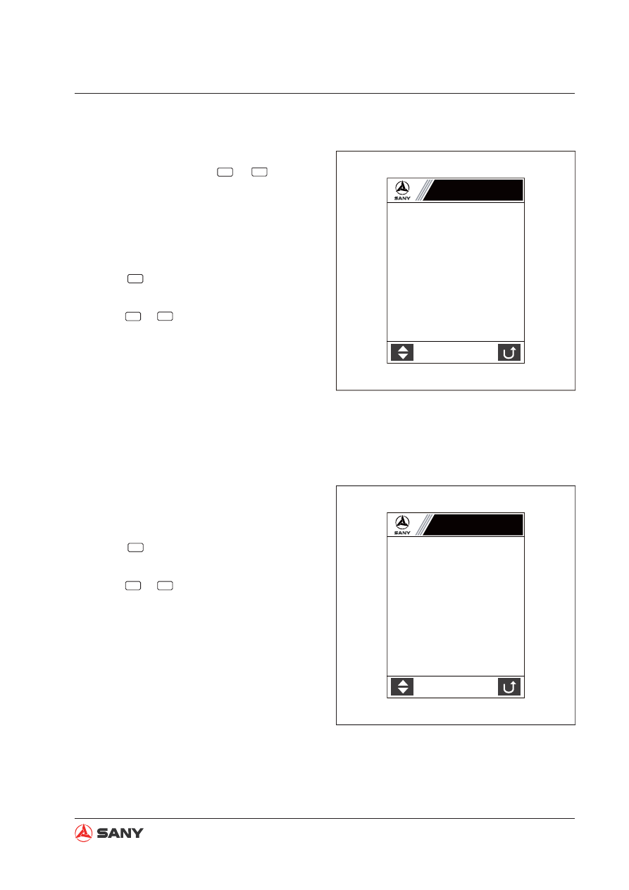
4. Engine & Throttle Signal

Select “Running Parameter” on the Informa-
tion Menu page and press 

F2

 or 

Enter

, and the 

display moves to Engine & Throttle Signal 
page. This page is a real-time display of the 
running parameter of the engine and throttle.

Operation

Press 

F1

 to go to “Pilot Pressure Signal”

page.

Press 

F5

 or 

ESC

 to return to the “Information

Menu”.

5. Pilot Pressure Signal

This page is a real-time display of the pilot 
pressure signal of the hydraulic system.

Operation

Press 

F1

 to go to “Main Pump and Main

Valve Signal” page.

Press 

F5

 or 

ESC

 to return to the “Information

Menu”.

XP1251203008

Engine & Throttle Signal

Coolant temp °C:

Fuel level %:

Oil press kPa:

Throttle gear:

Eng speed rpm:

Gear position V:

Throt position V:

XP2051203009

Boom UP kg:

Boom DOWN kg:

Arm IN kg:

Arm OUT kg:

Bucket DIG kg:

Bucket DUMP kg:

Swing kg:

Travel L kg:

Travel R kg:

Pilot Pressure Signal

4-208

Structure and Function

6. Main Pump & Main Valve Signal

This page is a real-time display of the main 
pump and main valve signals of the hydraulic 
system.

Operation

Press 

F1

 to go to “Engine & Throttle Sig-

nal” page.

Press 

F5

 or 

ESC

 to return to the “Information

Menu”.

7. Fault Information

Select “Fault Information” on the Information 
Menu page and press 

F2

 or 

Enter

, and the dis-

play moves to Fault Information page. This 
page lists important machine fault information.

Operation

Press 

F1

 to go to the next page.

Press 

F5

 or 

ESC

 to return to the “Information

Menu”.

XP2051203010

Main Pump & Main Valve Signal

Pump1 press   kg

Pump2 press   kg

Prop valve1 current mA

Prop valve2 current mA

Bucket confluence valve 

ż

Swing priority valve 

ż

Boom priority valve 

ż

Hi/Lo speed switch 

ż

XP13041501

Current fault code:XXX

XXX:

XXX:

XXX:

XXX:

XXX:

XXX:

XXX:

XXX:

XXX:

XXX:

XXX:

XXX:

XXX:

XXX:

XXX:

XXX:

XXX:

Fault Information

4-209

Structure and Function

8. Throttle Installation

Select “Throttle Installation” on the Information 
Menu page and press 

F2

 or 

Enter

, and the dis-

play moves to Throttle Installation page. This 
page displays throttle installation assistance 
function.

Operation

Press 

F2

 to switch between auto-idle and

full speed.

Press 

F3

 to select high or low travel

speed.

For machines equipped with SYFCS con-
trollers, press 

F4

 to switch between 

rpm

(blue) and 

rpm

 (red).

Press 

F5

 or 

ESC

 to return to the “Information

Menu”.

NOTE: For machines equipped with SYFCS 
controllers, when engine speed calibration is 
not successful, a question mark will appear.

9. System Language

Select “System Language” on the Information 
Menu page and press 

F2

 or 

Enter

, and the dis-

play moves to this page. 

Operation

Press 

F2

 to select 

.

Press 

F3

 to select English.

You can also use 

 or 

 to select a sys-

tem language on the list.

Press 

F5

 or 

ESC

 to return to the “Information

Menu”.

XP2051203013

n/min

AUTO

rpm

Throttle Installation

Current gear N

Eng speed rpm

Gear position V

Throttle position V

1200 ?

XP2051203014

English Systems

Ё ᭛ ㋏ 㒳

Ё᭛

(QJ

System Language

4-210

Structure and Function

10. System Time Setup

Select “System Time Setup” on the Informa-
tion Menu page and press 

F2

 or 

Enter

, and the 

display moves to this page. You can set sys-
tem time on this page.

Operation

Use 

 and

 to change the number 

where the cursor blinks.

Use 

 and 

 to move the cursor.

Press 

F1

 or 

Enter

 to save adjusted time.

Press 

F5

 or 

ESC

 to return to the “Information

Menu”.

NOTE: 

When 

F1

 or 

Enter

 is pressed, the screen 

displays “Setup Finished” on the bottom. If 
system time has been adjusted, it cannot be 
adjusted again until the system is re-ener-
gized. 

11. GPS Monitoring

Remark:

Longitude: “E” stands for “East”, while “W”
for “West”.

Latitude: “N” stands for “North”, while “S”
for “South”.

Altitude: “P” means “Above Sea Level”,
while “N” means “Below Sea Level”.

Select “GPS Monitoring” on the Information 
Menu and press 

F2

 or 

Enter

 to view this page.

Operation

Press 

F5

 or 

ESC

 to return to the “Information

Menu”.

XP2051203015

System Time Setup

Current time and time zone:
1234·12·12   12:12:12 W

Setup time and time zone:
1234·12·12   12:12:12 W

Use 

>Ĺ@>Ļ@>ĸ@>ĺ@

 to adjust system time

XP130426011

G%
G%
G%
G%

GPS Monitoring 

Longitude °

˖

Latitude  °

˖

Elevation  m:
Speed Km/h: 
Satellite No.:  
Comm index

˖

S/N ratio 1

˖

S/N ratio 2

˖

S/N ratio 3

˖

S/N ratio 4

˖

4-211

Structure and Function

The blue-white bars show signal-to-Noise
ratio ranges from 0 to 99.

When the altitude is nonzero and the longi-
tude and latitude is zero, it means that the
system is receiving GPS data, yet still in
the process of precise positioning.

GPS is normal when the signal indicator
shows 1023, otherwise it is abnormal when
the signal indicator shows 615.

When the signal indication changes to 0
from 7, a connection failure occurs either
in the SIM card or in the antenna.

When the signal indication changes to
0 from 15, it is either because the GPS
service is not available, or the SIM card
charge is overdue, or the GPS network is
abnormal.

When the signal indication changes to 0
from 31, it is because the monitoring cen-
ter suspends.

12. Brightness Adjustment

Press 

F4

 on the Information Menu Password 

Entry page to go to Bright Adjustment page. 
This page is used to adjust monitor screen 
brightness.

Operation

Press 

F1

 to decrease brightness level.

The progress bar moves to the left side.
Minimum brightness is 10%.

Press 

F2

 to increase brightness level. The

progress bar moves to the right side. Maxi-
mum brightness is 100%.

Press 

F3

 to save brightness adjustment.

Press 

F5

 to return to the “Information

Menu”.

XP2051203029

Brightness: 20%

Brightness Adjustment

Tips: Use F3 to save brightness value.

4-212

Structure and Function

13. System Setup password entry

Press 

F4

 on the Information Menu page to en-

ter the Password Entry page before accessing 
the System Setup page.

Operation

1. For password entry method, see Informa-

tion Menu Password Entry page.

2. When all the five digits of the password

have been entered, press 

F3

 or 

Enter

. If the

password is correct, the display moves to
the “System Setup” page; if not, please try
again.

3. Press 

F5

 or 

ESC

 to return to the Home

page.

NOTE: Contact your local dealer to obtain this 
password.

14. System Setup

This page is used to set up machine con

fi

 gu-

ration.

Operation

Press 

F1

 to select the item below the high-

lighted one. The highlighter returns to the
top after the bottom item. You can also use

 and 

 to move the highlighter up and 

down.

Press 

F2

 or 

Enter

 to access the selected en-

try.

Press 

F5

 or 

ESC

 to return to the Home

page.

XP130426012

System Setup

Please enter the password

XP2051203016

System Setup

Machine configuration

Service hour setup

Hydraulic oil temperature

Machine configuration setup

4-213

Structure and Function

15. Machine Confi guration password entry

Select Machine Configuration on the System 
Setup list and press 

F2

 or 

Enter

, and the display 

moves to the Password entry page before ac-
cessing the Machine Con

fi

 guration page.

Operation

1. For password entry method, see Informa-

tion Menu Password Entry page.

2. When all the five digits of the password

have been entered, press 

F3

 or 

Enter

. If the

password is correct, the display moves to
the “Machine Configuration” page; if not,
please try again.

3. Press 

F5

 or 

ESC

 to return to the “System

Setup” page.

16. Machine Confi guration

You can view machine con

fi

 guration  informa-

tion on this page.

Operation

Press 

F5

 or 

ESC

 to return to the “System

Setup” page.

XP13060801

System Setup

Please enter the password

XP13041502

Machine Configuraiton

Machine model

Machine No.:

Engine model:

Hydr system model:

Controller model:

Structure and Function

17. Service Hour Setup password entry

Select “Service Hour Setup” on the System 
Setup list and press 

F2

 or 

Enter

, and the display 

moves to the Password entry page before ac-
cessing the Service Hour Setup page.

Operation

1. For password entry method, see Informa-

tion Menu Password Entry page.

2. When all the five digits of the password

have been entered, press 

F3

 or 

Enter

. If the

password is correct, the display moves
to the “Service Hour Setup” page; if not,
please try again.

3. Press 

F5

 or 

ESC

 to return to the “System

Setup” page.

18. Service Hour Setup

This page is used to set up machine service 
hours.

Operation

Use 

 and

 to change the number 

where the cursor blinks.

Use 

 and 

 to move the cursor.

Press 

F1

 or 

Enter

 to save adjusted time.

Press 

F5

 or 

ESC

 to return to the “System

Setup” page.

NOTE: 

When 

F1

 or ENTER is pressed, the 

screen displays “Setup Finished” on the bot-
tom. If system time has been adjusted, it can-
not be adjusted again until the system is re-
energized. 

XP13060802

System Setup

Please enter the password

Current service hour

Use 

>Ĺ@>Ļ@>ĸ@>ĺ@

 to adjust service hour

100 h 50 m

Setup service hour

100 h 50 m

XP2051203021

Service Hour Setup

4-215

Structure and Function

19. Machine Confi guration Setup password
entry

Select “Machine Configuration Setup” on the 
System Setup list and press 

F2

 or 

Enter

, and the 

display moves to this Password entry page.

Operation

1. For password entry method, see Informa-

tion Menu Password Entry page.

2. When all the five digits of the password

have been entered, press 

F3

 or 

Enter

. If the

password is correct, the display moves to
the “Machine Con

fi

 guration Setup” page; if

not, please try again.

3. Press 

F5

 or 

ESC

 to return to the “System

Setup” page.

XP13060803

㋏㒳䆒㕂

䇋䕧ܹᴎ఼䜡㕂䆒ᅮᆚⷕ˖

4-216

Structure and Function

20. Machine Confi guration Setup

This page is used to set up machine con

fi

 gu-

ration after installation of the monitor.

Operation

Press 

F1

 to change machine model.

Press 

F2

 to change engine model.

Press 

F3

 to change hydraulic system

model.

Press 

F4

 to change controller model.

Press 

F5

 to save machine configura-

tion. The screen displays “Setup finished.
Please re-energize the system.”

Press 

Enter

 to move the cursor between dif-

ferent parts in the machine number.

Use 

 and 

 to increase and decrease

the selected machine number by 100 each
time.

Use 

 and 

 to increase and decrease

the selected machine number. One quick
pressing increase or decrease the number
by 1. Long pressing increase or decrease
the number in a quicker pace.

Press 

ESC

 to return to the “System Setup”

page.

XP13041503

Mach Eng

Hydr Cont

Machine Config Setup

Machine model:

Engine model:

Hydraulic model:

Control model:

Machine No.:

Use

>Ĺ@>Ļ@>ĸ@>ĺ@

 to set up machine number

4-217

Structure and Function

Remark:

The machine serial number is composed of 
4 parts: 1) Production year, 2) Product code, 
3) Tonnage code, 4) Alteration code, 5) Serial
number, and 6) Tail number “8”.

1) Press 

Enter

 to move the cursor to different

part (Production year, Product code and
Serial number) in the machine number.

2) When the cursor moves to Production year

and Alteration code, press 

 and 

 to

increase or decrease Production year and
Alteration code by 1 each time.

3) When the cursor moves to Tonnage code,

press 

 and 

 to increase or decrease

tonnage code by 1 each time; or press
and 

 to increase or decrease tonnage

code by 100 each time.

4) When the cursor moves to Serial number,

press 

 and 

 to increase or decrease

this number by 1 each time. Long press-
ing to change the number in a quick pace.
Press 

 and 

 to increase or decrease

this number by 100 each time.

5) The machine number has 4 adjustable dig-

its. Use 

 and 

 to switch between the

four digits, and use 

 and 

 to change

the value on a digit. The value of the first
digit from the left could be any numbers
from 0 to 9 and any letters from A to Z; the
value of the rest three digits could only be
any number from 0 to 9. When the number
exceed 9999, capital letter from A to Z will
have to be used. A, B, C, D, E ...  means
respectively 10000, 11000, 12000, 13000,
14000, 15000 .... For example: 10000 will 
be written as A000; 11020 as B020, 12999
as C999.

4-218

Structure and Function

21. Hydraulic Oil Temperature

Select “Hydraulic Oil Temperature” on the Sys-
tem Setup list and press 

F2

 or 

Enter

, and the 

display moves to this page.

Operation

Press 

F5

 or 

ESC

 to return to the “System

Setup” page.

XP2051203028

Hydraulic Oil Temp

Hydraulic Oil Temp:

4-219

Structure and Function

22. Lockout Information (Level 1)

This display indicates that the machine has 
entered lockout state (level 1). 

Operation

Press 

F5

 to enter “System Unlock” page.

NOTE: 

Contact your local dealer to unlock the 

machine when the system is locked.

NOTE: 

Contact your local dealer to unlock the 

machine when the system is locked.

30. Lockout Information (Level 2)

This display indicates that the machine has 
entered lockout state (level 2). 

Operation

Press 

F5

 to enter “System Unlock” page.

XP13041504

System locked

Contact manufacturer to unlock system

Lockout Information

Macine model:

Machine No.:

Machine state:

Current time:

Lockout (1)

System locked

Contact manufacturer to unlock system

Macine model:

Machine No.:

Machine state:

Current time:

Lockout (2)

XP13041505

Lockout Information

Standard Values

Standard Values

5 Standard Values

5.1  Standard Values of Engine - related Parts ............................................................... 5-3
5.2  Standard Values of Chassis-related Parts ............................................................... 5-4

Standard Values

5-2


WARNING

Read and understand all safety precau-
tions and instructions in this manual be-
fore reading any other manuals provided 
with this machine and before operating or 
servicing the machine. Also read the safety 
information on machine decals before per-
forming any operations. Failure to do so 
can cause machine damage, personal in-
jury or death.

5-3

Standard Values

Item

Measurement condition

Unit

Std. value for 

new machine

Permissible value

Engine Speed

High Idling

rpm

2,060 ± 70

2,060 ± 70

Low Idling

rpm

1,050 ± 50

1,050 ± 50

Rated Speed

rpm

2,000

2,000

Intake Pres-
sure
 (Negative 
Pressure) 

Air Cleaner Outlet Location

Arm-In Over

fl

 ow+Max. rpm

kPa

{mmH

2

O}

Min. 133

{Min. 1,000}

Min. 133

{Min. 1,000}

Exhaust Color

At Sudden Acceleration

Bosch

Index

Max.25

35

At High Idling

Valve Clear-
ance

Intake Valve

mm

0.25

0.152 ~ 0.381

Exhaust Valve

mm

0.51

0.381 ~0.762

Compression 
Pressure

Oil Temp: 40~60°C

Engine Speed 250 rpm

Mpa

{kg/cm²}

Min. 2.41

{Min. 24.6}

1.69

{17.2}

Blow-by Pres-
sure

Coolant Temp: Working Range

Arm-In Over

fl

 ow: Max. rpm

kPa

{mmH

2

O}

Max. 0.98

{Max. 100}

1.96

{200}

Oil Pressure

High Idling

MPa

{kg/cm²}

Min. 0.29

{Min. 3.0}

0.25

{2.5}

Low Idling

MPa

{kg/cm²}

Min. 0.10

{Min. 1.0}

0.07

{0.7}

Oil Temp. 

Full Speed Range (In Oil Pan)

°C

80 ~ 110

120

Fan Belt Ten-
sion

Between fan belt pulley and
alternator belt pulley

Deflection when pressed with

fi

 nger force of 58.8 N {6 kg}

mm

8.0

Min. 6, Max. 10

A/C Compres-
sor Belt Ten-
sion

Between fan belt pulley and
compressor belt pulley

Deflection when pressed with

fi

 nger force of 58.8 N {6 kg}

mm

5 ~ 8

5 ~8

5.1  Standard Values of Engine - related Parts

5 STANDARD VALUES


Content      ..     17      18      19      20     ..