SANY Crawler Hydraulic Excavator SY195C9, SY205C9, SY215C9, SY225C9. Service Manual - page 17
 

  Index      Manuals     SANY Crawler Hydraulic Excavator SY195C9, SY205C9, SY215C9, SY225C9. Service Manual (2013)


Search            copyright infringement  


Content      ..     15      16      17      18     ..


SANY Crawler Hydraulic Excavator SY195C9, SY205C9, SY215C9, SY225C9. Service Manual - page 17


4-175

Structure and Function

ZX215-1002197

MAX

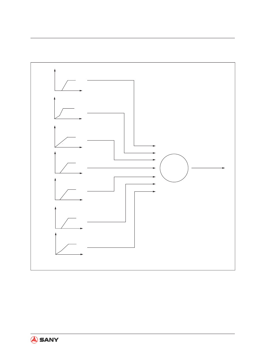
Bucket CURL PPC pressure

Arm OUT PPC pressure

Bucket DUMP PPC pressure

L. Travel PPC pressure

Swing PPC pressure

Arm IN PPC pressure

Boom RAISE PPC pressure

Pump 1
delivery
amount

Pump 1
delivery
amount

Pump 1
delivery
amount

Pump 1
delivery
amount

Pump 1
delivery
amount

Pump 1
delivery
amount

Pump 1
delivery
amount

Corresponding
delivery output

4.9.4.1 Electrical positive fl ow control

4-176

Structure and Function

ZX215-1002198

MAX

Pump 2
delivery
amount

Pump 2
delivery
amount

Pump 2
delivery
amount

Pump 2
delivery
amount

Pump 2
delivery
amount

Pump 2
delivery
amount

Pump 2
delivery
amount

Boom RAISE PPC pressure

Arm IN PPC pressure

Arm OUT PPC pressure

Bucket CURL PPC pressure

Bucket DUMP PPC pressure

Boom LOWER PPC pressure

R. Travel PPC pressure

Corresponding
delivery output

4-177

Structure and Function

Function

Use the joystick pilot pressure signal di-
rectly as the hydraulic pump discharge
control signal. Pilot pressure is applied on
the valve stem and, on the other hand, is
collected by the controller. The controller
keeps the discharge amount of the hydrau-
lic pump at the speci

fi

 ed value of the cor-

responding pilot pressure according to the
functional relation between the set hydrau-
lic pump discharge amount and pilot pres-
sure. During combined operation, the set
discharge amount of each operation shall
be added.

Operation

When the work equipment is operating, the
controller collects the signal of pilot pres-
sure sensor, and determines the control
discharge amount of pump 1 and pump 2
according to the pressure signal.

4-178

Structure and Function

4.9.4.2  Constant power control

ZX215-1002199

P

Max

P

Max

P

0

Q

P

Pressure

Flow

Pump P-Q curve

Function

Calculation of theoretical maximum dis-
charge amount of the pump. The system
applies constant power control. The two
adjustor act together hydraulically, and
keep two executing unit of the same speci-
fication and acting together in synchroni-
zation. The change of pump discharge is
determined by the sum of operating pres-
sure of the two hydraulic pumps 

P

. When

 is met, the sum of the 

power of the two hydraulic pumps remains 
constant below the power of the engine. 

Operation

When the work equipment is working, the
controller collects the throttle gear signal,,
a constant current value is provided and
pump power control is achieved.

4-179

Structure and Function

Function

Changing of the engine speed due to load
change controls the pump power, and en-
gine output can be used more efficiently.
(This function can also prevent the engine
from losing control when the machine is
operating under harsh conditions (eg. high
- altitude area).

Operation

The engine control panel controls the target 
operating speed of the engine. 

The engine controller collects the actual
speed signal from the ECM, and preforms
a closed loop control with the target oper-
ating speed. Then, the controller involves
the output of closed-loop control with the
calculation of the solenoid valve control
signal, and sends the final adjusting cur-
rent signal to the pump proportional sole-
noid valve.

The solenoid valve feeds pilot pressure oil
to the pump adjustor according to the sig-
nal of the controller, and controls the pump
discharge amount.

ESS control

4-180

Structure and Function

Valve control function

Bucket 

fl

 ow control

Swing priority control

ZX215-1002200

M

P

F

R

Hi

Lo

Main valve

Bucket Confluence

Swing priortity

Engine

Fuel injection
pump

Throttle
motor

Speed
sensor

Servo

Servo

Main
pump

Press.sensor

Press.sensor

(Control signal)

(Control signal)

(Engine speed signal)

(Throttle position feedback signal)

(Motor drive signal)

Fuel control dial

Proportional

valve

Proportional

valve

(CAN

bus)

Monitor

Controller

Swing signal

Bucket DUMP signal

Bucket DIG signal

Arm OUT signal

Arm IN signal

R. Travel signal

L. Travel signal

Boom UP signal

Boom DOWN signal

4.9.5  Valve control function

4-181

Structure and Function

Function

Control the pump swash plate angle ac-
cording to the operation of bucket control
lever.

Operation

When the bucket control lever is operated,
the controller collects the signal from the
bucket DUMP pressure sensor and bucket
CURL pressure sensor, and controls the
bucket con

fl

 uence proportional valve.

4.9.5.1 Bucket fl ow control

ZX215-1002201

Max

Min

Swash plate angle

Bucket control lever 
PPC pressure

ZX215-1002202

750mA

300mA

Bucket confluence
proportional
valve current

Bucket control lever 
PPC pressure

4-182

Structure and Function

4.9.5.2  Swing priority control

Function

Pressurized oil from pump 1 bypasses
bucket 1 valve spool, and flows first to
swing motor valve spool to activate swing

fi

 rst.

Operation

When signals from pump 1 pressure sen-
sor, arm pressure sensor and swing pres-
sure sensor meet the following conditions,
the controller activates the solenoid valve.
The solenoid valve conducts pilot pressure
oil to arm 

fl

 ow controller and limits the al-

ternate circuit of arm 1 valve spool. Swing
valve spool first ensures swing motor
power, preventing the counter acting force
when the arm is retracting from affecting
the positioning of the upper swing struc-
ture.

Operating condition

Swing pressure sensor: signal output avail-
able

Arm pressure sensor: signal output avail-
able

4-183

Structure and Function

ZX215-1002203

M

P

F

R

Hi

Lo

Regulator

Travel motor

Main valve

Travel Speed
solenoid valve

L. Travel pressure sensor

R. Travel pressure sensor

Regulator

Main pump

Engine

Throttle
motor

Servo

Servo

Injection
pump

Controller

Monitor

(CAN

bus)

(Control signal)

(Control signal)

(Throttle position feedback signal)

(Motor drive signal)

Fuel control dial

4.9.6  

Duo travel speed control

Structure and Function

Function

Control travel mode.

Operating condition

When Hi speed travel mode on the monitor
is enabled.

Remark: 

When one side of the tracks is lifted off the 
ground by the work equipment and rotating, 
pressure at one side of the pump increases, 
which makes the lifted track rotate very fast. 
When the machine is traveling under Hi speed 
mode, even if work equipment is being op-
erated (work equipment pressure sensor is 
switched ON), travel mode remains in Hi travel 
mode. 

Operation

When the travel mode is set at LO speed,
the swash plate angle of the travel motor is
the largest, and travel speed is low.

When the controller receives the signal
from the travel pressure sensor under the
conditions below, it activates the solenoid
valve. Then, the solenoid valve conducts
pilot pressure oil to the swash plate angle
control valve of the travel motor, and re-
duces the swash plate angle to increase
travel speed.

4-185

Structure and Function

ZX215-1002204

M

P

F

R

Hi

Lo

Heat

Main valve

Start switch

Preheat s/w

Preheat relay

Coolant

tempe

sensor

Throttle motor

Servo

Main
pump

Controller

Servo

Monitor

(CAN

bus)

Engine

(Control signal)

(Control signal)

(Motor drive signal)

(Throttle position feedback signal)

Fuel control dial

4.9.7  

Engine preheating/overheating alarm 

4-186

Structure and Function

Function

Preheating control

Operation

This function shall be used in combination
with the preheating switch located on the
right armrest. Turn the engine start key
counterclockwise to the HEAT position and
hold on, the engine will start preheating.
When released, the key will return to the
OFF position automatically and preheating
stops.

Operating condition

Power ON. Start key set at the HEAT posi-
tion.

Preheating switch: ON

4.9.7.1 Engine preheating

4-187

Structure and Function

Function

When engine coolant temperature be-
comes excessively high (above 110°C)
during operation, overheating alarm will be
displayed on the monitor screen.

Operation

The controller collects signal from the cool-
ant temperature sensor. When coolant
temperature rises too high, alarming infor-
mation will be generated and transmitted
to the machine monitor.

Operating condition

Power ON.

Coolant temperature above 110°C.

4.9.7.2  Engine overheating alarm

Function

The engine controller collects signal from
the engine oil pressure sensor. When en-
gine speed exceeds 600 rpm, if oil pres-
sure is too low, alarming information will be
generated and transmitted to the machine
monitor. The alarm indicator lights up when
the monitor receives the signal.

4.9.8  Engine oil under

pressure alarm

4-188

Structure and Function

ZX215-1002205

(

Throttle signal)

Engine
throttle
controller

Control lever signal

Controller

Monitor

(CAN

bus)

Engine

Fuel control dial

(

Motor drive signal)

(

Potentiometer signal)

Right joystick

Boom

Bucket

DOWN

UP

IN

OUT

Left joystick

Swing

Arm

R

L

CURL

DUMP

L.Travel

Travel lever

R.Travel

Forward Reverse

Forward

Reverse

4.9.9  

Auto deceleration/acceleration control

Structure and Function

Operation

About 3 second after all control levers are
neutralized, engine speed will drop to the

fi

 rst deceleration level about 100 rpm lower

than the set speed. After another 3 sec-
onds engine speed enters low speed (1400
rpm) to reduce the loss of the hydraulic
system and engine wear, and reduce fuel
consumption and noise. When the control
lever is operated again, the engine  speed
rises instantly to the previous level.

If any control lever is operated while the
engine speed is kept at decelerated level,
engine speed will rise instantly to the level
set by the fuel control dial.

Function

If all the control levers are neutralized, en-
gine speed will drop to the medium level
automatically to reduce fuel consumption
and noise.

If any of the levers is operated, the engine
speed rises to the set level instantly.

ZX215-1002206

3s

(1350rpm)

Drop 

100rpm

Control lever

Operated

Unoperated

Operated

Set rpm


Time (s)

less than 2 S

Deceleration

Less than 1 S

Speed (rpm)

4-190

Structure and Function

4.9.10  

Engine speed calibration function

ZX215-1002207

SW

LED

7

LED

LED

MEMORYON

DOWN

UP

RPW

H

S

L

A/I

H

S

L

A/I

SW

M

P

F

R

Hi

Lo

R. Travel signal

L. Travel signal

Boom UP signal

Boom DOWN signal

Arm IN signal

Arm OUT signal

Bucket DIG signal

Bucket DUMP signal

Swing signal

Calibtator

(CAN

bus)

Controller

Monitor

Fuel control dial

(Engine speed signaL)

(Control signaL)

(Control signaL)

(Motor drive signaL)

(Throttle position feedback signaL)

Engine

Speed

sensor

Main pump

Main valve

Bucket confluence

Swing pripority

Pressure sensor

Servo

Servo

Pressure sensor

Injection
pump

Throttle
motor


Content      ..     15      16      17      18     ..