SANY Crawler Hydraulic Excavator SY195C9, SY205C9, SY215C9, SY225C9. Service Manual - page 15
 

  Index      Manuals     SANY Crawler Hydraulic Excavator SY195C9, SY205C9, SY215C9, SY225C9. Service Manual (2013)


Search            copyright infringement  


Content      ..     13      14      15      16     ..


SANY Crawler Hydraulic Excavator SY195C9, SY205C9, SY215C9, SY225C9. Service Manual - page 15


4-143

Structure and Function

3. Feeding of refrigerant

ZX215-1002153

ZX215-1002154

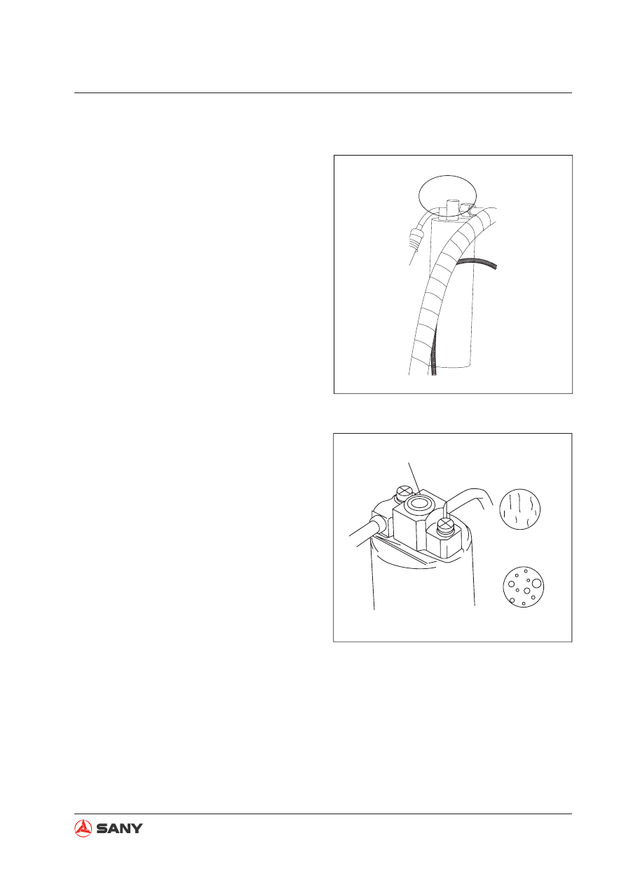
Proper filling

Inadequate filling

Sight glass

Filling method and volume:

1) Refrigerant: HFC-134a

2) Feeding volume: 850±50 g (for reference)

3) Feeding method: Feeding of liquid refrig-

erant from the low-pressure end is not al-
lowed. If feeding operation fails, discharge
the refrigerant that has been fed before re-
feeding.

Inspect the state of the refrigerant in the
A/C circulation system through the sight
glass:

1) Correct feeding: Foam is hardly observed

when the refrigerant is flowing. When en-
gine speed increases from idling to 1500
rpm, foam disappears and the refrigerant
turns clear.

2) Over-feeding: No foam can be observed

when refrigerant is 

fl

 owing.

3) Under-feeding: Foam is always observed

when refrigerant is 

fl

 owing.

4-144

Structure and Function

4. Evacuation

No moisture shall exit in the air condition-
ing unit. Refrigerant (R134a) is soluble in
water. Very small amount of moisture in
the unit can cause the ori

fi

 ce of the expan-

sion valve to ice up, or cause the compres-
sor valve to rust. To avoid such problems,
moisture in the system shall be removed
before refrigerant is added. To minimize
the residual moisture in the system, mois-
ture in the system can evaporate through
evacuating.

Evacuating steps

Step 1: Connect the manifold pressure gauge

1) Close the high-pressure valve (HI) and

low-pressure valve (LO) of the manifold
pressure gauge.

2) Connect the hoses (red, blue) to the auxil-

iary valve of the compressor.

Red hose – High pressure side (Mark D)

Blue hose – Low pressure side (Mark S)

NOTE

: Connect the end of the hose with a 

L  to the auxiliary valve of the compressor. 
If connected inversely, the valve will not 
open. Besides, do not inversely connect 
the high-pressure end and the low-
pressure end. 

3) Connect the green hose to the vacuum

pump.

ZX215-1002155

LO

HI

LO

HI

D

S

Lo-pres. valve (ON)

Hi-pres. valve(ON)

Lo-pres.
gauge

Hi-pres. gauge

Vacuum pump (running)

Compressor

Valve

Lo-pres.gauge

above 750mmHg 

ON ON

OFF OFF

Blue

Red

Green

Structure and Function

Step 2: Evacuation

1) Open the high-pressure valve (HI) and low-

pressure valve (LO) on the manifold pres-
sure gauge.

2) Turn on the vacuum pump and evacuate

for about 15 minutes.

3) When negative pressure reading on the

gauge (degree of vacuum) reaches above
750 mmHg, turn off the vacuum pump and
close the Hi-pressure valve and the Lo-
pressure valve on the gauge.

ZX215-1002156

Lo

Hi

Tighten pipe joint

Lo-press. gauge
returns to 0

Wait 5 min. or more

Lo-press. gauge

Pointer returns
to 0

Valve

OFF OFF

Step 3: Air - proof check

1) Keep the Hi- and Lo-pressure valve of the

manifold pressure gauge under closed
state for more than 5 minutes, and make
sure the pointer on the gauge does not re-
turn to zero.

2) If the pointer returns to near zero, a leak-

age is available somewhere. Check and
adjust the pipe joint. Tighten the joint and
conduct another evacuating operation until
no leakage is detected.

Structure and Function

Step 4: Leak check

1) Connect the green hose that is previously

connected to the vacuum pump  to the

fl

 uorine cylinder.

2) Connect the other end of the green hose

to the pressure gauge. Open the valve of
the cylinder and press the vent valve of the
pressure gauge. (Do not press the valve
with naked hand to avoid frostbite caused
by refrigerant).  Release the air in the
hose with the pressure of the refrigerant.
(Release the vent valve when you hear a
squeezing sound).

3) Add refrigerant until pressure reading on

the Lo-pressure gauge is 1kgf/cm² . Hi-
pressure valve of the gauge is open at this
time. Close the Hi-pressure valve when
feeding is 

fi

 nished.

4) Use a leak detector to check if leakage is

available in the cooling system.

5) Make necessary repairs (tightening) if leak-

age is observed.

ZX215-1002157

Lo Hi

R134a

Vent valve

Release air

Blue

Red

Green

To compressor

Fluorine cylinder

Open

Valve

OFF OFF

ZX215-1002158

R134a

D

S

Lo Hi

Lo Hi

OFF ON

OFF OFF

Lo-press gauge

at 1kgf/cm

2

Fluorine cylinder

Compressor

Open Hi-pres.valve

Lo-pres.valve (OFF)

Cylinder valve (ON)

Lo-pres. gauge
reads

1kgf/cm

2

Valve

4-147

Structure and Function

5. Refrigerant charging operation

When evacuation is 

fi

 nished, add refrigerant into the cooling system as per the following in-

struction:

Charge at the hi-pressure side

1. Remove the green hose of the manifold

pressure gauge from the vacuum pump
and connect it to the 

fl

 uorine cylinder.

2. Loosen the cylinder valve and press the

vent valve on the gauge. Use the pressure
of the refrigerant to release the air in the
hose.

NOTE: Release the vent valve when you
hear a hissing sound.

ZX215-1002159

Lo Hi

R134a

Loosen
this nut

OFF OFF

Vent valve

Blue

Red

Green

To compressor

Fluorine cylinder

Open

Valve

ZX215-1002160

R134a

D

S

Lo Hi

Lo Hi

Open Hi-press. valve

Lo-press.
valve (OFF)

Fluorine cylinder
valve (ON)

 A cylinder
(about 600g)

Valve

g

Do not operate compressor

g

Do not open Lo-pressure valve

ON

OFF

OFF OFF

3. Open the hi-pressure valve of the manifold

pressure gauge and the cylinder valve with
the engine stopped. Fill about 600g of re-
frigerant.

4. Close the hi-pressure valve of the pressure

gauge and shut the cylinder valve.


CAUTION

Do not press the valve with naked hand
to avoid frostbite.

Evacuation starts

Evacuation ends

Air-proofness check

Add refrigerant kgf/cm

2


Air leak check

Add refrigerant 

Air leak check

Performance testing

Wait 5 min

.

More than 15 min.


Pres. gauge

    normal

75cm-Hg or more

Tighten pipe joint

Pres. gauge

abnormal

Check leak point

(1) Compressor stopped, charge at hi-press end

(2)Compressor running, add at lo-press end

4-148

Structure and Function

ZX215-1002161

H I

1300~1500rpm

ON

Hi-press. valve (OFF)

Manifold pressure
        gauge

Start the engine

ZX215-1002162

Lo Hi

Lo Hi

Valve

        Fluorine cylinder
(never placed upside down)

Compressor
running

Hi-press. valve (OFF)
(Never open it)

Lo-press. 
valve (ON)

Fluorine cylinder
valve (ON)

Lo-press. gauge
(1.5~2.5kgf/cm

2

)

When no foam

is observed

Hi-press. gauge
(13~17kgf/cm

2

)

ON OFF

OFF OFF

Charge at the lo-pressure side (refi ll)

1. Check that the hi-pressure valve of the

manifold pressure gauge is closed.

2. Start the engine.

3. Turn on the A/C unit. Adjust Temperature

control switch to minimum.

4. Adjust engine speed to 1300 – 1500 rpm.

5. Open the Lo-pressure valve of the mani-

fold pressure gauge and the cylinder valve.
Add refrigerant until no foam is observed
through the sight glass.

Remark:

Manifold pressure gauge reading (for refer-
ence): 

HIGH pressure:

 13~17kgf/cm² (when ambient temperature 
is 30°C)

LOW pressure: 

1.5~2kgf/cm² (when ambient temperature 
is 30°C).


CAUTION

Do not operate the compressor when
refrigerant charging is in progress.
Otherwise, refrigerant will counterflow
and cause the cylinder and hoses to ex-
plode.

Operating the compressor with no re-
frigerant in the system will cause dam-
age to the compressor.

Do not open the lo-pressure valve of the
manifold pressure gauge; otherwise,
the compressor will be damaged.

Structure and Function

6. When refrigerant charging is finished,

close the Lo-pressure valve of the mani-
fold pressure gauge and the valve of the

fl

 uorine cylinder.

7. Check carefully for air leaks with a leak

detector.

8. When ambient temperature is low

When refrigerant charging gets difficult
due to low temperature, put the cylinder in
warm water (max. 40

°

C).

9. When ambient temperature is high

When ambient temperature is very high,
cool the compressor with an electrical fan.

ZX215-1002163

Lo Hi

Lo Hi

Water less than 40°C
(Do not use hot water)

Compressor
running

Hi-pressure valve
        (OFF)

Lo-pressure
valve (ON)

Cylinder valve
      (ON)

ON OFF

When no foam

is seen

Valve

OFF OFF


CAUTION

Opening the Hi-pressure valve of the
pressure gauge will cause pressurized
gas to counterfl ow and cause the hoses
and the fl uorine cylinder to explode, re-
sulting in serious damage.

When engine is running and charging in
progress, placing the fluorine cylinder
upside down will cause liquid refriger-
ant to be sucked directly into the com-
pressor and cause liquid compression,
resulting in equipment damage.

Structure and Function

Replace the fl uorine cylinder

When the refrigerant in a cylinder is used up, 
replace the cylinder as per the following in-
struction: 

1. Close the Hi- and Lo-pressure valves of

the manifold pressure gauge.

2. Raise the needle and disc plate of the cyl-

inder and remove the empty cylinder.

3. Install a new cylinder onto the cylinder

valve.

4. Release the air in the hose as per the fol-

lowing instruction:

1) Tighten the valve of the 

fl

 uorine cylinder,

and then, loosen it a bit.

2) Open the Lo-pressure valve of the mani-

fold pressure gauge a bit.

3) Press the vent valve and allow a little re-

frigerant to come out. Immediately close
the valve of the cylinder and the Lo-
pressure valve of the manifold pressure
gauge.

ZX215-1002164

Air hose connector

Handle

Gasket

Needle valve

Refrigerant
cylinder

Disc plate

ZX215-1002165

Lo Hi

R-134a

OFF

Loose

Blue

Red

Green

To compressor

Refrigerant cylinder

Loosen the valve a bit

Valve

Lo-pressure
valve

Close the Lo-pressure valve 
once you hear the hissing sound

5. Turn the handle of the cylinder valve to

pierce the cylinder and continue charging
operation.


CAUTION

Do not press the valve with naked hand
to avoid frostbite.

Structure and Function

6. Fault testing with manifold pressure gauge

Cooling system under normal condition

Gauge reading:

Lo-pressure end: 0.15~0.25 Mpa (1.5~2.5 Kgf/cm²)

Hi-pressure end: 1.37~1.57 Mpa (14~16 Kgf/cm²)

After the engine has been preheated, read the pressure value on the gauge under the following 
conditions:

1) Temperature at air inlet: 30 – 35°C

2) Engine speed: 1500 rpm

3) Fan speed: High

4) Temperature control: Minimum.

5) Air circulation mode: Recirculation

ZX215-1002167

0

0

01

02

03

04

05

05

0

0

35

MPa

MPa

{cmHg   kgf/cm

2

}

{cmHg   kgf/cm

2

}

5

3

30

25

25

20

10

1

15

2

15

35

-01

-01

-76

-76

-50

06

07

08

R134a

085

8.5

8

7

5

6

4

3

2

1

15

Structure and Function

Symptom

Cause

Analysis

Remedy

When the system is
operating, pressure
at the Lo-pressure
end unstable (some-
times vacuum,
sometimes normal)

Moisture in the system
ices up at the expan-
sion valve causing
circular temporary
stop. When ice melts,
the system becomes
normal again.

Over-saturation of de-
hydrator.

Moisture in the system
ices up at the expan-
sion valve and hinders
the circulation of the
refrigerating system.

Replace receiver/
dehydrator

Remove the mois-
ture in the system
through constant
pumping.

Add proper volume
of new refrigerant.

Moisture in the refrigerating system

Symptom: Intermittent refrigeration to non-refrigeration

ZX215-1002168

0

0

01

02

03

04

05

05

0

0

35

MPa

MPa

{cmHg   kgf/cm

2

}

{cmHg   kgf/cm

2

}

5

3

30

25

25

20

10

1

15

2

15

35

-01

-01

-76

-76

-50

06

07

08

085

8.5

8

7

5

6

4

3

2

1

15

Structure and Function

Insuf

fi

 cient refrigeration

Symptom: Insuf

fi

 cient refrigeration 

Symptom

Cause

Analysis

Remedy

Pressure at both Hi- and
Ho-pressure ends very
low

Foam is continuously ob-
served via the sight glass

Insuf

fi

 cient refrigeration.

Air leaks
somewhere
in the refrig-
erating sys-
tem

Insuf

fi

 cient

refrigerant in the
system

Leak of refriger-
ant

Check for air leakage with a leak
detector. Make necessary re-
pairs.

Add proper amount of refriger-
ant.

When connected with the gauge,
if the reading is near zero, set
the system under vacuum state
after inspection  and repair.

ZX215-1002169

0

0

01

02

03

04

05

05

0

0

35

MPa

MPa

{cmHg   kgf/cm

2

}

{cmHg   kgf/cm

2

}

5

3

30

25

25

20

10

1

15

2

15

35

-01

-01

-76

-76

-50

06

07

08

085

8.5

8

7

5

6

4

3

2

1

15

Structure and Function

Defective refrigerant circulation

Symptom: insuf

fi

 cient refrigeration

Symptom

Cause

Analysis

Remedy

Pressure at both
Hi- and Lo-pressure
sides very low

Frosting on the pip-
ing between parts
and reservoir

Contaminant in the
reservoir hinders the

fl

 ow of refrigerant.

Blocked reservoir

Replace reservoir

ZX215-1002170

0

0

01

02

03

04

05

05

0

0

35

MPa

MPa

{cmHg   kgf/cm

2

}

{cmHg   kgf/cm

2

}

5

3

30

25

25

20

10

1

15

2

15

35

-01

-01

-76

-76

-50

06

07

08

085

8.5

8

7

5

6

4

3

2

1

15

Structure and Function

Refrigerant not circulating

Symptom: Non-refrigeration (intermittent refrigeration)

Symptom

Cause

Analysis

Remedy

Vacuum at Lo-pres-
sure side; pressure
at Hi-pressure side
extremely low

Frosting or conden-
sation on the pipes
around the expan-
sion valve or receiv-
er/dehydrator

Moisture or contami-
nant in the refrigerant
hinders the 

fl

 ow of

refrigerant.

Air leak at the thermal
pipe of the expansion
valve hinders the 

fl

 ow

of refrigerant.

Refrigerant not
circulating

Check the expansion valve
and ERP.

Blow the contaminant in the
expansion valve or replace
the expansion valve if nec-
essary.

Replace the receiver

Release internal air and
add refrigerant. If air leaks
from thermal pipe, replace
expansion valve.

ZX215-1002171

0

0

01

02

03

04

05

05

0

0

35

MPa

MPa

{cmHg   kgf/cm

2

}

{cmHg   kgf/cm

2

}

5

3

30

25

25

20

10

1

15

2

15

35

-01

-01

-76

-76

-50

06

07

08

085

8.5

8

7

5

6

4

3

2

1

15

Structure and Function

Over-charging of refrigerant or insuf

fi

 cient refrigeration of condenser

Symptom: Insuf

fi

 cient refrigeration

Symptom

Cause

Analysis

Remedy

Pressure at both Hi-
and Lo-pressure
sides very high

No foam can be ob-
served via the sight
glass even when
engine speed drops.

Over-

fi

 lling of refriger-

ant in the system. Re-
frigerating performance
inadequate.

Insuf

fi

 cient refrigera-

tion of condenser

Over-

fi

 lling of refriger-

ant

Condenser 

fi

 ns clogged

or fan motor error.

Clean the condenser

Check the working
condition of fan  mo-
tor

If the two above
items are normal,
check the volume
of refrigerant. Add
refrigerant.

ZX215-1002172

0

0

01

02

03

04

05

05

0

0

35

MPa

MPa

{cmHg   kgf/cm

2

}

{cmHg   kgf/cm

2

}

5

3

30

25

25

20

10

1

15

2

15

35

-01

-01

-76

-76

-50

06

07

08

085

8.5

8

7

5

6

4

3

2

1

15

Structure and Function

Air is observed in the refrigerating system

Symptom: Poor refrigeration

NOTE: If refrigerant is added with no evacuation operation performed, the following gauge read-
ing will appear:

Symptom

Cause

Analysis

Remedy

Pressure at both Hi- and
Lo-pressure ends very
high

Lo-pressure piping feel-
ing hot

Foam is observed
through the sight glass

Air enters the re-
frigerating system

Air enters the refriger-
ant system

Insuf

fi

 cient evacuation

Check if compressor
oil is contaminated
or inadequate.

Evacuate and add
new refrigerant.

ZX215-1002173

0

0

01

02

03

04

05

05

0

0

35

MPa

MPa

{cmHg   kgf/cm

2

}

{cmHg   kgf/cm

2

}

5

3

30

25

25

20

10

1

15

2

15

35

-01

-01

-76

-76

-50

06

07

08

085

8.5

8

7

5

6

4

3

2

1

15

Structure and Function

Improper installation of expansion valve/thermal pipe defect (wide opening)

Symptom: insuf

fi

 cient refrigeration

Symptom

Cause

Analysis

Remedy

Pressure at both
Hi- and Lo-pressure
ends very high

Frosting or conden-
sation on Lo-pres-
sure piping

Expansion valve de-
fect, or improper instal-
lation of thermal pipe

Over-

fi

 lling of

refrigerant in
Lo-pressure
piping

Expansion
valve opening
very wide

Check the installation of
thermal piping

If thermal piping is normal,
check the expansion valve.
Replace defective expan-
sion valve if observed.

ZX215-1002174

0

0

01

02

03

04

05

05

0

0

35

MPa

MPa

{cmHg   kgf/cm

2

}

{cmHg   kgf/cm

2

}

5

3

30

25

25

20

10

1

15

2

15

35

-01

-01

-76

-76

-50

06

07

08

085

8.5

8

7

5

6

4

3

2

1

15


Content      ..     13      14      15      16     ..