SANY Crawler Hydraulic Excavator SY195C9, SY205C9, SY215C9, SY225C9. Service Manual - page 16
 

  Index      Manuals     SANY Crawler Hydraulic Excavator SY195C9, SY205C9, SY215C9, SY225C9. Service Manual (2013)


Search            copyright infringement  


Content      ..     14      15      16      17     ..


SANY Crawler Hydraulic Excavator SY195C9, SY205C9, SY215C9, SY225C9. Service Manual - page 16


Structure and Function

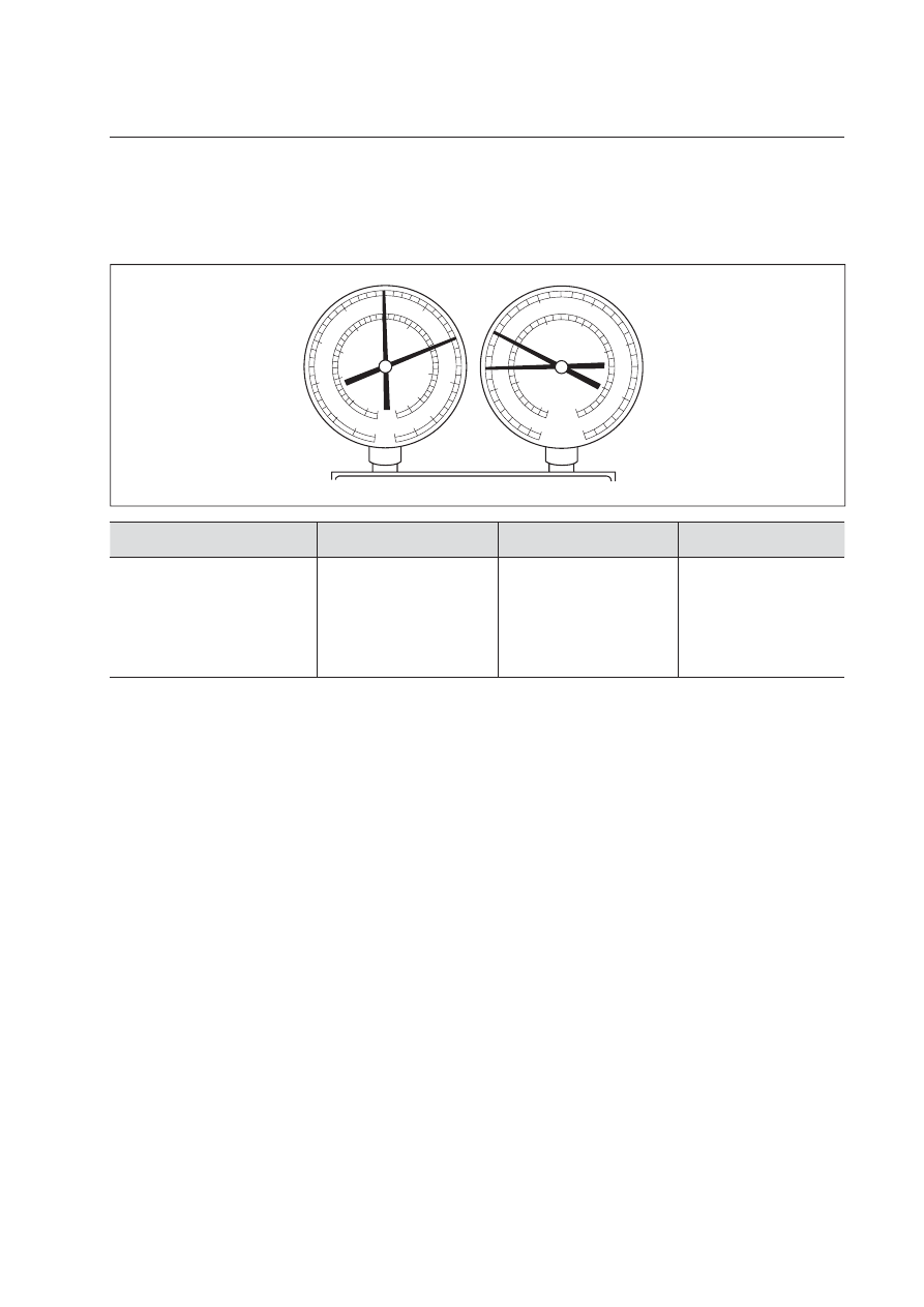
Compressing error

Symptom: No refrigeration

Symptom

Cause

Analysis

Remedy

Pressure at Lo-pressure
side very high

Pressure at Hi-pressure
side very low

Compressor internal
leakage

Compressing fault;

Leaking or damaged
valve, loosened parts

Repair or replace
compressor

ZX215-1002175

0

0

01

02

03

04

05

05

0

0

35

MPa

MPa

{cmHg   kgf/cm

2

}

{cmHg   kgf/cm

2

}

5

3

30

25

25

20

10

1

15

2

15

35

- 01

-01

-76

-76

-50

06

07

08

085

8.5

8

7

5

6

4

3

2

1

15

4-160

Structure and Function

4.7.14 Compressor oil

Oil shall be added into the A/C system for lubrication. Compressor oil is solved in the refrigerant 
and circulates in the system. When the air conditioning system is shut down, compressor oil will 
stay inside the components. If no compressor oil is added into the system when replacing compo-
nents, inadequate lubrication will result. Add compressor oil according to the chart below:

Replaced component

Compressor

Condenser

Evaporator

Volume (ml)

See "CAUTION" below

40

40

Compressor oil grade

ND8# (10P, 10PA, 10S series compressor)

ND9#(TV series compressor)


CAUTION

Add oil into a new compressor according to the required volume of the system. When
the compressor is to be replaced, discharge the surplus oil in it.

Over-fi lling of compressor oil will reduce the refrigerating capacity. Short of compres-
sor oil in the system will cause compressor abnormality.

Protect pipe joints and O-rings from contamination when disassembling the compres-
sor.

4-161

Structure and Function

1)

Battery 

relay

2)

Battery

3)

Engine start switch

4)

Fuel control dial

5)

Start 

motor

6)

Engine 

controller

7)

Fuel injection pump

8)

Throttle 

motor

9)

Shutdown 

device

ZX215-1002176

4

3

2

5

9

1

Z

8

7

6

Outline

Start and stop the engine only with the  en-
gine start switch (3).

The controller (6) receives the signal from
the fuel control dial (4) and transmits the
drive signal to the throttle motor (8) to
control the governor lever angle of fuel
injection pump (7) and control the engine
speed.

When engine start switch (3) is turned to
the OFF position, the shutdown device (9)
pulls the flame-out arm on the injection
pump to the “parking” position and cuts the
engine fuel supply. Then, the engine stops.

4.8  

Engine Control

4-162

Structure and Function

4.8.1  System operation  

When it happens, the controller checks the
signal voltage from the fuel control dial and
sets the engine speed to the speed set by
the fuel control dial.

Engine startup

When the start switch is turned to the
START position, the starting signal is trans-
mitted to the start motor. Then, the start
motor rotates to start the engine.

The controller sends a driving signal to the 
throttle motor according to the signal volt-
age to control the fuel injection pump, and 
eventually controls the engine speed.

ZX215-1002177

C

BR

P

M

s

Lo

Lo

Hi

Hi

B

P

P

E

E

E

B

L

SW

S

B

s

(Regulating signal

Engine

(Power)

Controller

(Start switch ON signal)

(Starting signal)

Start S/W

Fuel ctrl dial

Throttle On

Governor
motor

Alternator

Bat. relay

Lock
relay

Shutdown
device

Shutdown 

relay

(Starting signal)

Safety
relay

Drive signal

(Potentiometer singal)

Throttle Off

Pilot S/W

Start motor

Starting relay

ZX215-1002178

C

BR

P

M

s

Lo

Lo

Hi

Hi

B

P

P

E

E

E

B

L

SW

S

B

s

Throttle On

(Regulating signal

Governor
motor

Alternator

Bat. relay

Lock
relay

Engine

(Power)

Controller

(Start switch ON signal)

Start motor

Shutdown
device

Shutdown 

relay

(Starting signal)

(Starting signal)

Safety
relay

Drive signal

(Potentiometer singal)

Throttle Off

Starting relay

Pilot S/W

Start S/W

Fuel ctrl dial

ZX215-1002179

C

BR

s

Lo

Lo

Hi

Hi

B

P

P

E

E

E

B

L

SW

S

B

s

Throttle On

(Regulating signal

Governor
motor

Alternator

Bat. relay

Lock
relay

Engine

(Power)

Controller

(Start switch ON signal)

Start motor

Shutdown
device

Shutdown 

relay

(Starting signal)

(Starting signal)

Safety
relay

Throttle Off

Starting relay

Pilot S/W

Start S/W

Fuel ctrl dial

Engine speed control

The fuel control dial sends a signal voltage
corresponding to the rotation angle to con-
troller.

Engine shutdown

When the start switch is turned to the OFF
position, the shutdown device cuts off the
fuel supply and stops the engine.

4-163

Structure and Function

4.8.2  

Components

4.8.2.1  

Fuel control dial

1)

Knob

2)

Dial

3)

Spring

4)

Ball

5)

Potentiometer

6)

Connector

ZX215-1002180

25°

140°

9×10°

1

2

3

4

5

5V

0V

VR

a

b

c

6

a

b

c

Yellow

Blue

Red

Level 1

Left limit

Right limit

Level 10

4-164

Structure and Function

Function

Turning of the fuel control dial changes the
resistance of the sliding rheostat inside the
dial and the voltage signal collected by the
controller. The controller calculates the col-
lected signals and drives the throttle motor
via signal output and controls the volume
of the injection pump so that the engine
can run at an optimal speed.

When throttle voltage is beyond the area,
the controller sends out alarm code and
the engine runs at low idle. The area under
the sloping line is the abnormality detection
area.

Remark: 

The left limit is 0%; and the right limit is 100%. 

ZX215-1002181

%

V

100

0

0.25 1.72

4.49 4.75 5

Voltage

˄

V

˅

Dial angle

4-165

Structure and Function

4.8.2.2  

Controller

ZX215-1002182

TYPE

USE FOR
NO

A

ZX215-1002183

........

........

........

........

...................

...................

...................

...................

A1

A2

Controller

Controller port layout

4-166

Structure and Function

A1

Pin 

No.

Signal name

Input/

output

53

Rear pump pressure sensor

Input

54

Sensor power ground

Input

55

Sensor power ground

Input

56

Sensor power

Output

60

Monitor CAN Low

61

Calibrator CAN High

62

Calibrator CAN Low

66

Coolant temp very high

Input

67

R. travel pressure sensor

Input

68

Swing pressure sensor

Input

69

Bucket CURL pressure sensor

Input

70

Boom RAISE pressure sensor

Input

71

Arm IN pressure sensor

Input

72

Front pump pressure sensor

Input

73

Sensor PWR ground

74

Sensor PWR

Output

75

Sensor PWR

Output

76

State indicator

77

Monitor CAN High

78

Monitor CAN Low

79

Calibrator CAN Low

80

Calibrator CAN shield wire

81

Calibrator CAN High

A2

Pin 

No

.

Signal name

Input/

output

82

Travel speed switching solenoid

88

Front pump solenoid valve

89

Rear pump solenoid valve

97

Swing priority solenoid valve

98

Bucket con

fl

 uence solenoid valve

99

Boom priority 1

100 Boom priority 2
104 Motor drive signal +

113 Motor drive signal -
114 Power ground
115 Power ground
116 Power ground
117 Power ground
118 Power supply(24V constant)
119 Power supply(24V constant)

120 Power supply(24V constant)
121 Power supply(24V constant)

A1

Pin 

No.

Signal name

Input/

output

1

Power ground

2

Power ground

3

Power ground

4

Power supply(24V constant)

Input

5

Power supply(24V constant)

Input

11

Fuel level sensor

Input

15

Throttle position signal

Input

19

Engine speed signal

Input

22

RS232 ground

23

RS232 receive

24

Enable

30

Coolant temperature sensor signal Input

31

Oil temperature sensor signal

Input

33

Backup pilot pressure signal

Input

34

Fuel dial signal

Input

38

Engine speed signal ground

41

RS232 send

42

CPU mode

43

Enable

48

Engine oil pressure switch

Input

49

L. travel pressure sensor

Input

50

Bucket DUMP pressure sensor

Input

51

Boom LOWER pressure sensor

Input

52

Arm OUT pressure sensor

Input

Input and output signals

4-167

Structure and Function

4.9  

Electrical Control System

4.9.1  

Control function

Engine-Pump composite control function

Pump control function

Valve control function

Dual travel speed control 

Electronic control system

Auto-deceleration/acceleration control

Engine oil under-pressure alarm 

Engine preheating/overheating alarm

Engine speed calibration function

Self-diagnosis function

NOTE: For detailed information about self-diagnosis function, see "Troubleshooting"

4-168

Structure and Function

ZX215-1002184

1

2

3

5

6

7

8

9

10

11

17

12

13

14
15

16

4

Battery

Battery relay

Start switch

Preheating signal

Power ON signal

Starting signal

Monitor panel

Signal monitor info

Network signal

Working mode signal
Travel spd select signal
Auto-deceleration signal
Signal monitor info

Fuse

Swing priority signal

Fuel control dial

R. travel signal

L. travel signal

Boom UP signal

Boom DOWN signal

Arm IN signal

Arm OUT signal

Bucket CURL signal

Bucket DUMP signal

Swing signal

Travel spd select signal

Bucket confluence signal

Controller

Fuel level sensor

Hydraulic oil temp sensor

Hydraulic oil temperature signal

Relay

PPClock signal

Starting signal

Starting signal

Preheating signal

Heater relay

Engine speed

Motor drive signal

Throttle position feedback signal

Engine oil pressure

Coolant temp sensor

Engine speed sensor

Oil pressure switch

Coolant temp sensor

Alternator

Starting motor

Elct. intake air heater

Motor

Potentiometer

Engine

R.Pump EX press. signal

F. Pump EX press. signal

F. Pump control signal
R. Pump control signal

Charging indicator

Power supply

Power supply

Safety relay

Fuel level signal

4.9.2  

Machine control system diagram

4-169

Structure and Function

ZX225-1102049

1

2

3

4

5

6

7

8

9

10

11

17

12

13

16

15
14

F

R

PsP

XBp2

PnA2

R. travel pressure sensor

Boom UP pressure sensor

Arm IN pressure sensor

Arm OUT pressure sensor

Bucket CURL pressure sensor

Bucket DUMP pressure sensor

Swing pressure sensor

L. travel pressure sensor

Boom DOWN pressure sensor

PPC
Valve

PPC Basic pressure

PPC Lock
solenoid
valve

Bucket

confluence

solenoid

valve

Swing 

priority

solenoid

valve

Travel

speed

solenoid

valve

F. Pump oil-feed device

Work equipment actuator

Proportional valve

Servo

Main pump

Swing motor

Travel motor

Servo

Travel motor

Proportional valve

F. Pressure sensor

R. Pressure sensor

R. Pump oil-feed device

Work equipment actuator

Control valve
ports

Main valve

Remark: 

The diagram above illustrates the electrical control system. For hydraulic circuit diagram, see Hy-
draulic System section.

4-170

Structure and Function

ZX215-1002186

MIN

MAX

P2

P1

SW

LED

7

LED

LED

MEMORYON

DOWN

UP

RPW

H

S

L

A/I

H

S

L

A/I

SW

Arm IN/OUT

PPC valve

Travel

Boom UP/DOWN

Bucket DIG/DUMP

Operator cab

Fuel control dial

Monitor

Travel

Swing

MC Controller input

H/S/L/B

Auto-idle cancel

Travel speed swithing

Alarm output

Pressure
sensor

Option pressure
sensor

Pilot oil pressure

KC controller

Pressure
sensor

Pump proportional
pressure reduce
solenoid valve

Main control valve

Throttle motor

Motor

Potentio-
meter

Engine
Oil-feed
adjustment

Engine chamber

Pump

R. Pump control angle

F. Pump control angle

Engine speed

Actual throttle position feedback

Control motor

Fuel, coolant temp and others

PWR resouce DC24V

   (Battery)

CAN path

Calibrator

4.9.3  

Engine and pump composite control function

4-171

Structure and Function

Function

This function allows the operator to select
a working mode according to the job to
be performed and change engine power
output. Four different working modes are
available: H, S, L and B. To select a work-
ing mode, use the working mode selector
switch on the machine monitor.

The main controller controls the pump so
that it can absorb all the torque at the out-
put points of the engine depending on the
pump absorption torque speci

fi

 ed for each

mode, rotation set by the fuel control dial,
and actual engine speed.

Specifi cations

H mode

S mode

L mode

Engine 

speed

~1600

1600~1800 1800~2250

Power (KW)

60

84

115

Engine 

speed

~1600

1600~2250

Power (KW)

60

84

Engine 

speed

~2250

Power (KW)

60

ZX215-1002193

H

S

L

Engine torque

T

Engine speed N

ZX215-1002194

H

S

L

Engine power

KW

Engine speed N

ZX215-1002195

H

S

L

Pump output pressure

P

Pump delivery

Q

4-172

Structure and Function

ZX215-1002190

Engine torque

T

Engine speed N

ZX215-1002191

Engine power

KW

Engine speed N

ZX215-1002192

Pump output pressure

P

Pump delivery

Q

Control method of each working mode

H mode

The matching point of H mode: rated
speed 114kW/2050rpm

If pump load increases and pump pressure
rises, engine speed drops. In this case,
engine speed will rise to near the match-
ing point, allowing the pump controller to
reduce pump discharge. On the contrary, if
pump load decreases and pump pressure
drops, pump controller will continue to in-
crease pump discharge until engine speed
reaches the matching point.

4-173

Structure and Function

At this time, the controller keeps the pump
oil-suction torque in line with the stabling
motor curve, and controls engine speed
through combined control of the engine
and pump.

Power output rate of at each working mode

Mode

S

L

B

Power output rate

90%

80%

70%

ZX215-1002193

H

S

L

Engine torque

T

Engine speed N

ZX215-1002194

H

S

L

Engine power

KW

Engine speed N

ZX215-1002195

H

S

L

Pump output pressure

P

Pump delivery

Q

S mode/B mode/L mode

4-174

Structure and Function

ZX215-1002196

M

P

F

R

Hi

Lo

Swing signal

Bucket DUMP signal

Bucket DIG signal

Arm OUT signal

Arm IN signal

R. Travel signal

L. Travel signal

Boom UP signal

Boom DOWN signal

Speed
sensor

Engine

Fuel injection
pump

Throttle
motor

Main
pump

Servo

Servo

Press.sensor

Press.sensor

(Throttle position feedback signal)

(Motor drive signal)

Fuel control dial

(Control signal)

(Control signal)

(Engine speed signal)

Proportional

valve

Proportional

valve

Monitor

(CAN

bus)

Controller

4.9.4  

Pump control function


Content      ..     14      15      16      17     ..