SANY Crawler Hydraulic Excavator SY195C9, SY205C9, SY215C9, SY225C9. Service Manual - page 20
 

  Index      Manuals     SANY Crawler Hydraulic Excavator SY195C9, SY205C9, SY215C9, SY225C9. Service Manual (2013)


Search            copyright infringement  


Content      ..     18      19      20      21     ..


SANY Crawler Hydraulic Excavator SY195C9, SY205C9, SY215C9, SY225C9. Service Manual - page 20


5-4

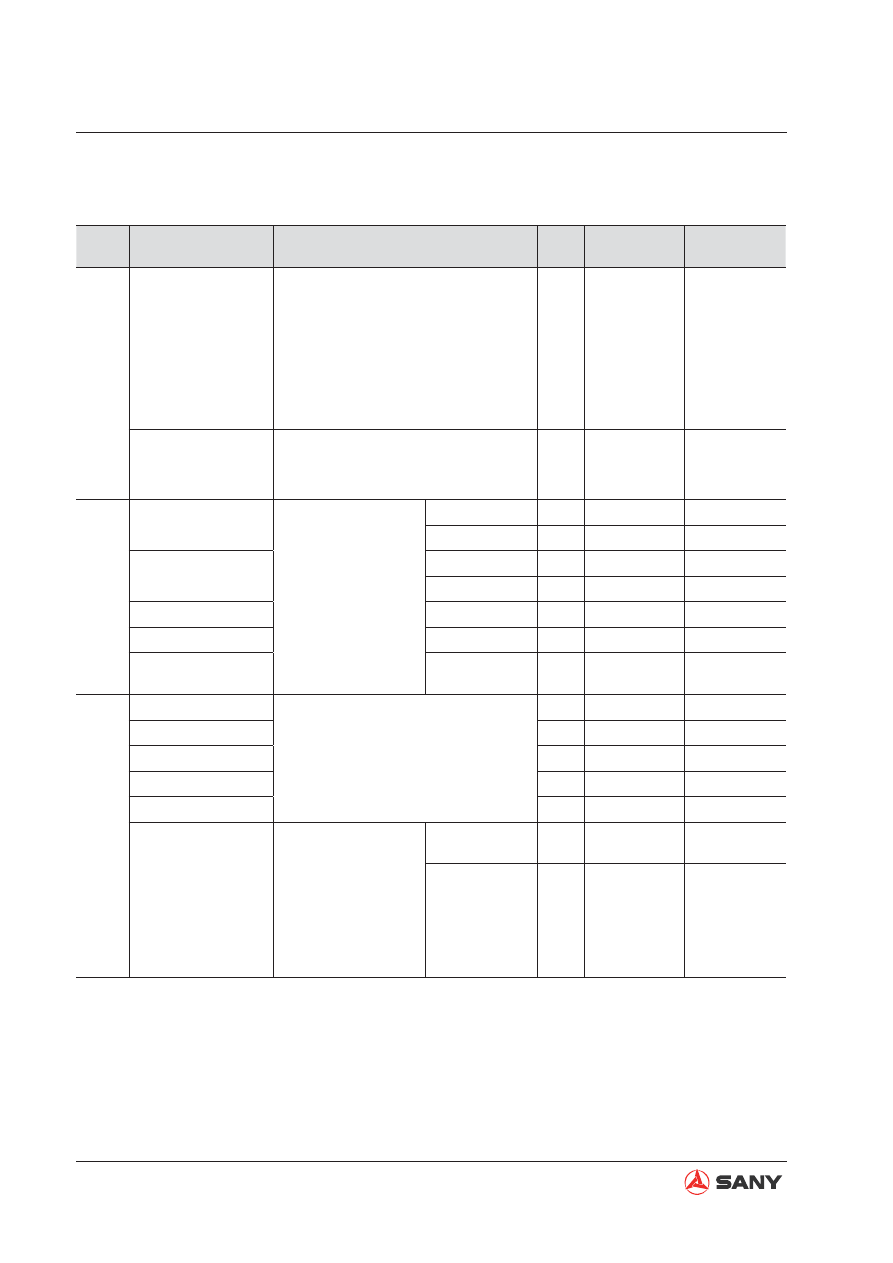
Standard Values

Categ.

Item

Measurement condition

Unit

Std. value for 

new machine

Permis-

sible value

       Engine Speed

2 pumps at relief

Engine coolant temperature: Within
operational range

Hydraulic oil temperature: Within
operational range

Engine running at high idle

Heavy-load operating mode (H)

Arm-in relief condition

rpm

2,030 ± 50

2,030 ± 50

Speed when auto 
deceleration is oper-
ated

Engine running at high idle

Auto idling switch on

All control levers neutral

rpm

1,400 ± 50

1,400 ± 100

Spool Stroke

Boom control valve

Engine stopped

See Control valve.

UP

mm

11.5 ± 0.5

11.5 ± 0.5

DOWN

mm

9.5 ± 0.5

9.5 ± 0.5

Arm control valve

IN

mm

11.5 ± 0.5

11.5 ± 0.5

OUT

mm

9.5 ± 0.5

9.5 ± 0.5

Bucket control valve

DIG/DUMP

mm

9.5 ± 0.5

9.5 ± 0.5

Swing control valve

Travel (L&R)

mm

9.5 ± 0.5

9.5 ± 0.5

Travel control valve

Forward &

Reverse

mm

9.5 ± 0.5

9.5 ± 0.5

Control Lever stroke

Boom control lever

Engine stopped

Control lever grip at center

Max. reading at stroke end (except
lever play in NEUTRAL  position)

mm

85 ± 10

85 ± 10

Arm control lever

mm

85 ± 10

85 ± 10

Bucket control lever

mm

85 ± 10

85 ± 10

Swing control lever

mm

85 ± 10

85 ± 10

Travel control lever

mm

115 ± 12

115 ± 12

Play of control lever

Engine stopped

Slightly push the
control lever. Stop
pushing when re-
sistance is felt.

Max. reading at

stroke end.

Work Equip-

ment

mm

Max. 15

Max. 20

Stroke

mm

Max. 20

Max. 25

5.2  Standard Values of Chassis-related Parts

5-5

Standard Values

Categ.

Item

Measurement condition

Unit

Std. value for 

new machine

Permis-

sible value

Operating Force of Control Lever/

Pedal

Boom control 
lever

Hydraulic oil temp: Within operational
range

Engine running at high idle

Control lever grip at center

Pedal at tip

Max. reading at stroke end

N

{kgf}

Max. 19.6

{Max. 2.0}

Max. 24.5

{Max. 2.5}

Arm control 
lever

Max. 19.6

{Max. 2.0}

Max. 24.5

{Max. 2.5}

Bucket con-
trol lever

Max. 15.6

{Max. 1.6}

Max. 21.6

{Max. 2.2}

Swing control 
lever

Max. 15.6

{Max. 1.6}

Max. 21.6

{Max. 2.2}

Travel control 
lever

Max. 30.4

{Max. 3.1}

Max. 39.2

{Max. 4.0}

Travel control 
pedal

Max. 93.1

{Max. 9.5}

Max. 107.8

{Max. 11}

Hydraulic Pressure

Unloaded 
pressure

Hydraulic oil temp: Within operational
range

Engine running at high idle

Working mode: H

All control levers in neutral position

Hydraulic pump output pressure

MPa

{kg/cm²}

0~1.0

{0~10}

0~2.0

{0~20}

Boom relief


Hydraulic oil temp: Within operational 
range

Operate corresponding control lever
after engine runs at high idling speed.

Working mode: H

Hydraulic pump output pressure with
all measurement circuits relieved

34.3 ± 1.0

{350 ± 10}

33.3 ~ 35.3

{340 ~ 360}

Arm relief

34.8 ± 1.0

{355 ± 10}

33.3 ~ 36.8

{340 ~ 375}

Bucket relief

34.8 ± 1.0

{355 ± 10}

33.3 ~ 36.8

{340 ~ 375}

Swing relief

Hydraulic oil temp: Within operational 
range

Operate corresponding control lever
after the engine runs at high idling
speed.

Working mode: H

Hydraulic pump output pressure with
all measurement circuits relieved

25.5 ± 1.0

{261 ± 10}

24.5 ~ 27.5

{250 ~280}

Travel relief

33.4 ± 1.0

{342 ± 10}

32.4 ~ 34.4

{330 ~ 351}

Control circuit 
source pres-
sure

Hydraulic oil temp: Within operational
range

Engine running at high idle

Self pressure reducing valve output
pressure with all control levers in
NEUTRAL position

3.9 ± 0.2

{40 ± 2}

3.7 ~ 4.1

{37 ~ 41}

5-6

Standard Values

Categ.

Item

Measurement condition

Unit

Std. value for 

new machine

Permis-

sible value

Swing

Swing 
brake 
angle

Hydraulic oil temp: Within operational range

Engine running at high idle

Working mode: H

Swing circle misalignment amount when stopping
after one turn

For measuring posture see Swing 1.

Deg.

mm

Max. 100

 (—) 

Max. 130

 (—) 

Time 
taken 
to start 
swing

Hydraulic oil temp: Within operational range

Engine running at high idle

Working mode: H

Time required for passing points 90°and 
180° from starting point

For measuring posture see Swing 1.

90° sec.

3.1 ± 0.3

Max. 3.7

180° sec.

4.4 ± 0.4

Max. 5.5

Time 
taken to 
swing

Hydraulic oil temp: Within operational range

Engine running at high idle

Working mode: H

Time required for 5 turns after making initial 1
turn

For measuring posture see Swing 1.

sec.

27 ± 3.5

Max. 30

Hydraulic 
drift

Hydraulic oil temp: Within operational range

Engine stopped

Keeping the upper structure transverse on a
grade of 15°. For more information see Swing 2.

Notching a mating mark on inner and outer races
of the swing circle

Mating mark misalignment amount during 5 min.

mm

0

0

Motor 
leakage

Hydraulic oil temp: Within operational range

Engine running at high idle

Swing lockout switch: ON

Leakage amount for 1 minute during swing relief

ml/

min

Max. 5

Max. 10

T

ravel

Travel 
speed
(unload-
ed)

Hydraulic oil temp: Within operational range

Engine running at high idle

Working mode: H

Time required for track shoes to make 5
turns after making one initial idle turn

For more information on measuring posture
see Travel 1.

Lo

sec.

51.3 ± 5.1

46.2 - 60.4

Hi

28.0 ± 1.4

26.6 - 31.4

5-7

Standard Values

Cat.

Item

Measurement Condition

Unit

Std. value for 

new machine

Permis-

sible value

T

ravel

T

ravel speed

(Actual run)

Hydraulic oil temp: Within operational range

Engine running at high idle

Working mode: H

Level ground

Time required for traveling 10m after 10m trial run

For measuring posture see Swing 2.

Lo

sec.

20 ± 2.5

17.5~22.5

Hi

13 ± 2.5

11.5~15.5

Deviation

Hydraulic oil temp: Within operational range

Engine running at high idle

Working mode: H

Travel Speed: Low

Hard level ground

Amount of deviation (

χ

) while traveling 20m after initial

10m trial run

For measuring posture see Travel 2/3.

mm

Max. 800

Max. 900

Hydraulic drift

Hydraulic oil temp: Within operational range

Engine stopped

Park the machine on a grade of 12°, with the sprocket
in the downhill direction

Measure the sliding distance for 5 minutes

For measuring posture see Travel 4.

mm

0

0

Leakage of 

travel motor

Hydraulic oil temp: Within operational range

Engine running at high idle

Traveling with the sprocket locked

Oil leakage amount for one minute with traveling in re-
lief condition

mm

13.6

27.2

W

ork Equipment

Hydraulic drift

Bucket 

tips

Hydraulic oil temp: Within operational range

Flat and level ground

Bucket full of earth or with rated load (0.8m

³

: 1,440 kg)

Boom horizontal, arm fully retracted and bucket cylin-
der fully extended

Engine stopped

Work equipment control lever in neutral position

Measure total amount of falling for 15 min. by measur-
ing the falling every 5 min. immediately after initial set-
ting

Buck

et tip lower distance

Boom cylinder: Cylinder retracting distance

Arm cylinder: Cylinder extending distance

Bucket cylinder: Cylinder retracting distance

For measuring posture see Work Equipment 1

.

mm

Max. 600

Max. 900

Boom 

cylinder

mm

Max. 20

Max. 27

Arm cylin-

der

mm

Max. 20 

Max. 20

Bucket cylinder

mm

Max. 45 

Max. 45

5-8

Standard Values

Categ.

Item

Measurement condition

Unit

Std. value for 

new machine

Permis-

sible value

W

ork Equipment

W

ork Equipment Speed

Boom

Hydraulic oil temp: Within operation-
al range

Engine running at high idle

Working mode: H

Time required for the bucket to raise
from the ground to its stroke end

For measuring posture see Work
Equipment 2.

UP

sec.

3.4 ± 0.4

Max. 4.8 

Arm

Hydraulic oil temp: Within operation-
al range

Engine running at high idle

Working mode: H

Time required from dumping stroke
end to digging stroke end

For measuring posture see Work
Equipment 3.

IN

sec.

2.8 ± 0.4

Max. 4.5

OUT

sec.

2.3± 0.3

Max. 3.5

Bucket

Hydraulic oil temp: Within operation-
al range

Engine running at high idle

Working mode: H

Time required from dumping stroke
end to digging stroke end

For measuring posture see Work
Equipment 4.

DIG

sec.

2.3 ± 0.4

Max. 3.4

DUMP

sec.

1.6 ± 0.3

Max. 2.3

5-9

Standard Values

Cat.

Item

Measurement condition

Unit

Std. value for 

new machine

Judgement 

criteria

W

ork Equipment

T

ime Delay

Boom

Hydraulic oil temp: Within operational range

Engine running at low idle

Working mode: H

Time required from maneuvering the joystick
to the moment that the bucket reaches the
ground and begins to push the machine up-
ward, within 50mm off the ground

For measuring posture see Work Equipment
5.

sec.

Max. 1.0

Max. 1.2 

Arm

Hydraulic oil temp: Within operational range

Engine running at low idle

Working mode: H

Average time required for operating the con-
trol lever back and forth till the arm starts to
move

For measuring posture see Work Equipment
6.

sec.

Max. 2.0

Max. 2.8

Bucket

Hydraulic oil temp: Within operational range

Engine running at low idle

Working mode: H

Average time required for operating the con-
trol lever back and forth till the arm starts to
move

For measuring posture see Work Equipment
7.

sec.

Max. 1.0

Max. 3.6

Internal Leakage

Cylinders

Hydraulic oil temp: Within operational range

Engine running at high idle

Leakage amount for one minute with cylinder
or travel measured at relief condition

ml/

min

5

20

Central Swivel 

Joint

10

50

Performance in Combined 

Operations

Amount of deviation in 

simultaneous operation of 

work equipment and travel

Hydraulic oil temp: Within operational range

Engine running at high idle

Working mode: H

Travel Speed: Low

Amount of deviation measured for 20 m after
traveling about 10 m on a hard level ground

For measuring posture see Travel 2.

mm

Max. 200

Max. 220

5-10

Standard Values

Machine postures for measuring (For all models)

Control value: Spool stroke

Travel 1: Travel speed (without load)

Travel 2: Travel speed (actual run), Travel de-
viation

ZX215-1003002

ZX215-1003005

ZX215-1003006

45°

Swing 1: Swing brake angle, time taken to 
start swing, time taken to swing

Travel 3: Travel deviation

ZX215-1003007

x

10m

ZX215-1003003

Swing 2: Hydraulic drift of swing

ZX215-1003004

15°

Sprocket

5-11

Standard Values

Travel 4: Hydraulic drift of Travel

ZX215-1003008

12°

Work equipment 1: Hydraulic drift of work 
equipment

ZX215-1003009

Work equipment 2: Boom speed

ZX215-1003010

Work equipment 3: Arm speed

ZX215-1003011

Work equipment 4: Bucket speed

Work equipment 5: Boom delay

ZX215-1003012

ZX215-1003013

5-12

Standard Values

Work equipment 6: Arm delay

Work equipment 7: Bucket delay

ZX215-1003014

ZX215-1003015

Testing and Adjusting

Testing and Adjusting

6-1

6 Testing and Adjusting

6.1  Engine Speed - Test and Calibrate .......................................................................... 6-3

6.1.1 Testing  ........................................................................................................... 6-3
6.1.2 Adjusting ........................................................................................................ 6-3

6.2  Exhaust Gas Color - Test ......................................................................................... 6-6
6.3  Valve Clearance - Adjust .......................................................................................... 6-8

6.3.1 Testing ............................................................................................................ 6-8
6.3.2 Adjusting ...................................................................................................... 6-10

6.4  Compression Pressure - Measure ..........................................................................6-11
6.5  Fuel Injection Timing - Test and Adjust .................................................................. 6-13

6.5.1 Testing .......................................................................................................... 6-13
6.5.2 Adjusting ...................................................................................................... 6-15

6.6  Engine Oil Pressure - Measure.............................................................................. 6-17
6.7  Engine Speed Sensor - Adjust ............................................................................... 6-19
6.8  A/C Compressor Belt Tension  - Test and Adjust ................................................... 6-20

6.8.1 Testing  ......................................................................................................... 6-20
6.8.2 Adjusting ...................................................................................................... 6-20

6.9  Swing Bearing Clearance - Measure ..................................................................... 6-22
6.10  Track Tension - Test and Adjust ........................................................................... 6-24

6.10.1 Testing ........................................................................................................ 6-24
6.10.2 Adjusting .................................................................................................... 6-25

6.11  Hydraulic Pressure in Hydraulic Circuits - Test and Adjust .................................. 6-26

6.11.1 Measuring .................................................................................................. 6-26
6.11.2 Adjusting ..................................................................................................... 6-28

6.12  Control Circuit Oil Pressure - Test and Adjust ...................................................... 6-30

6.12.1 Testing ........................................................................................................ 6-30
6.12.2 Adjusting .................................................................................................... 6-31

Testing and Adjusting

6-2


WARNING

Read and understand all safety precau-
tions and instructions in this manual be-
fore reading any other manuals provided 
with this machine and before operating or 
servicing the machine. Also read the safety 
information on machine decals before per-
forming any operations. Failure to do so 
can cause machine damage, personal in-
jury or death.

6.13  Solenoid Valve Output Pressure - Measure ......................................................... 6-32
6.14  Pilot Valve Output Pressure - Measure ................................................................ 6-34
6.15  Pilot Valves (Work Equipment and Swing) - Adjust ............................................. 6-36
6.16  Work Equipment Hydraulic Drift - Test ................................................................. 6-37
6.17  Residual Pressure in Hydraulic Circuit - Release ................................................ 6-40
6.18  Oil Leakage - Measure ........................................................................................ 6-41
6.19  Air in Each Component - Bleed............................................................................ 6-46

6-3

Testing and Adjusting

Engine speed calibrator

ID

Part Number

Part Name

1

B249900001206 Engine Speed Calibrator

6  TESTING AND ADJUSTING

6.1  

Engine Speed - Test and Calibrate

6.1.1 Testing 

Start the engine and keep the engine running 
until engine coolant temperature rises within 
the operational range. Key in the code on the 
monitor and check if the engine speed is nor-
mal in each throttle position. 

Testing Items: 

1. Engine speed at low idle

2. Engine speed at fuel control dial position

11 (H and S modes)

3. Engine speed at relief, with fuel control dial

placed at position 11 (H and S modes)

4. Engine speed at auto idle

6.1.2 Adjusting

Adjust the fixing point of the flexible shaft of 
the throttle motor. 

1. Connect the calibrator with the chassis

harness.

2. Push the memory switch of the calibrator

down to the OFF position.

3. Turn the start switch of the machine to the

ON position.

4. Start the engine. Check if engine speed is

within 1100±50 rpm range. (Throttle volt-
age at speed level 1 is 1.3±0.03V)

ENG.

WX215-1304008

Min. throttle

Max. throttle

Flexible shaft

Shaft bracket

Lock nut

Tighten

Loosen

Testing and Adjusting

NOTE:

In order to make sure speed calibration is suc-
cessful, deactivate auto-idle mode after the 
calibration process and check the idling speed 
at each speed level. If excessive variation is 
found between the real speed and the target 
speed, try automatic speed calibration once 
again. 

5. Tighten  the fixing position of the flexible

shaft when engine speed is lower than
1050 rpm; loosen the fixing position of the
flexible shaft when engine speed is higher
than 1150 rpm.

6. Shutdown the engine.

Speed calibration steps: 

1. Connect the calibrator with the chassis

harness.

2. Push the memory switch of the calibrator

down to the OFF position. Turn the start
switch of the machine to the ON position.

3. Start the engine. Engine speed “XXXX” will

be displayed on the screen display of the
calibrator. Press the H button and hold it,
the screen will display “E. XXXX”.

4. When automatic speed calibration is com-

pleted, the screen display of the calibrator
will change from “E. XXXX” to “XXXX”.

5. Shut off the engine.

WX215-1304009

MEMORY

DOWN

UP

RPM

H

S

L

A/I

H

S

L

A/I

ON

Memory s/w

H button

A/I button

Analog output

6-5

Testing and Adjusting

Engine speed reference (SY215C9)

Level

Speed (rmp)

Level

Speed (rmp)

S1

1100

H1

1100

S2

1200

H2

1200

S3

1300

H3

1300

S4

1500

H4

1500

S5

1600

H5

1600

S6

1650

H6

1700

S7

1750

H7

1800

S8

1850

H8

1900

S9

1950

H9

2000

S10

2050

H10

2100

S11

2150

H11

2200

6-6

Testing and Adjusting

6.2  Exhaust Gas Color - Test

Testing tools

ID

Model

Part Name

1

YDJ-2006

Smoke meter

2

SV-2TY

Opacimeter

1. Measure with a smoke meter

1) Put the 

fi

 lter paper into the smoke me-

ter.

2) Insert the waste gas intake pipe into

the exhaust pipe.

3) Start the engine and keep the engine

running until engine coolant tempera-
ture is within the operational range.

4) When engine speed increases sudden-

ly or is kept at high idle, direct exhaust
gas through smoke meter to the filter
paper.

5) Remove the 

fi

 lter paper from the smoke

meter. Read the smoke value through
the apparatus provided.

6) Remove the testing tools after measur-

ing. Make sure the machine goes back
to its normal state.

ZX215-1004002


CAUTION

Do not touch any hot parts when mount-
ing or dismounting the testing tools.

6-7

Testing and Adjusting

2. Measure with an opacimeter

1) Mount the opacimeter onto the exhaust

pipe by clamping it to the pipe outlet.

ZX215-1004003

ZX215-1004004

2) Open the opacimeter and preheat it for

about 15 minutes.

3) Start the engine and keep the engine

running until engine coolant tempera-
ture is within the operational range.

4) When engine speed increases sud-

denly or is kept at high idle, use the
opacimeter to read the smoke value of
exhaust gas.

5) Remove the testing tools after measur-

ing. Make sure the machine goes back
to its normal state.


Content      ..     18      19      20      21     ..