SANY Crawler Hydraulic Excavator SY115C9/135C/155H. Operation and Maintenance Manual - page 10
Troubleshooting
6.3 Towing the Machine
WARNING
Towing the machine improperly or using
wire cables beyond the specification could
lead to serious injury or death.
● Make sure that the wire cables used for
towing the machine are strong enough,
which may otherwise result in acci-
dents.
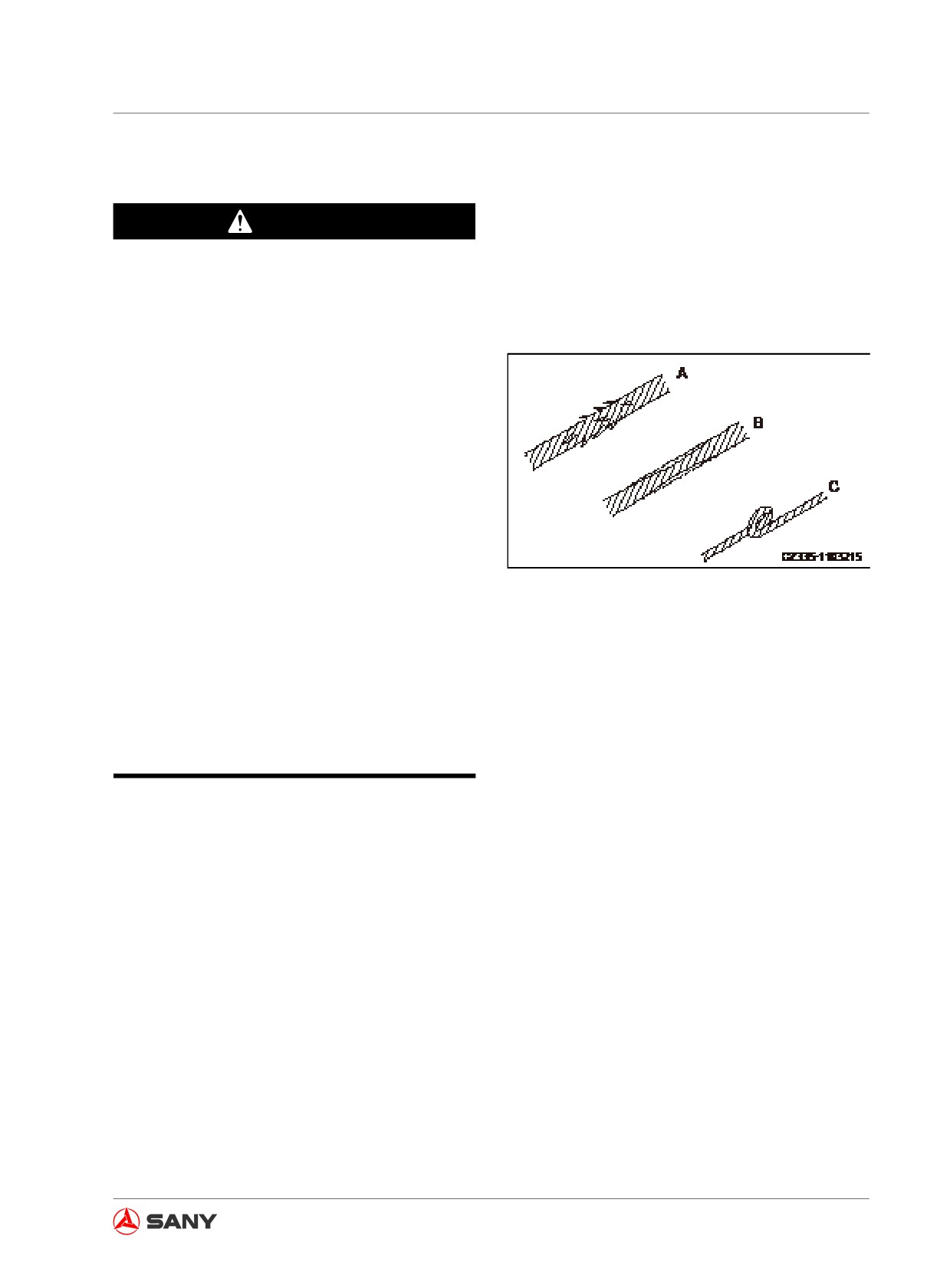
● While towing the machine, do not use
wire cables with broken wires (A), re-
duced diameter (B) or knot (C) in order
to prevent rupture of the wire cables.
● Always wear protective gloves when
handling wire cables.
Fig.
6-7
● Never tow the machine on a slope.
● Never stand between the towing ma-
chine and the towed machine when
performing towing operation.
● Operate the machine slowly and avoid
imposing sudden load on wire cable.
Note:
The towing operation must be performed with-
in the maximum towing capacity.
6-13
Troubleshooting
●●
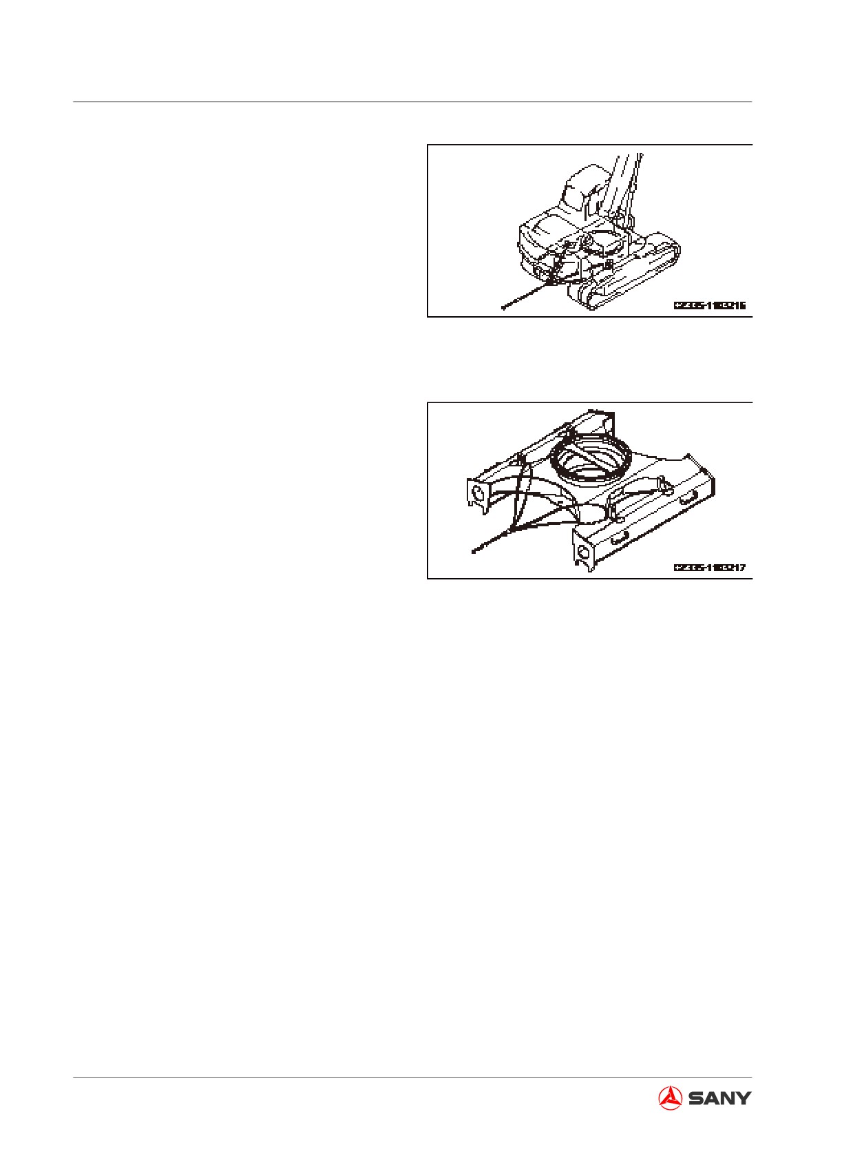
If the machine is trapped in mud and can-
not move out of the mud with its own force,
or the towing force of excavator is occu-
pied by heavy object, wire cables can be
used as shown in the right illustration.
●●
Place wood blocks or other protective
materials between where the wire cable
contacts the machine in order to prevent
friction between the wire cable and the ma-
Fig.
6-8
chine.
●
Keep the wire cable parallel to the ground
and align its direction with that of the track
frame.
●
Move at a speed of 1Km/h when towing
the machine. Tow the machine to a place
suitable for repair. Never tow the machine
over a long distance.
●
Towing of the machine is only allowed in
case of emergency.
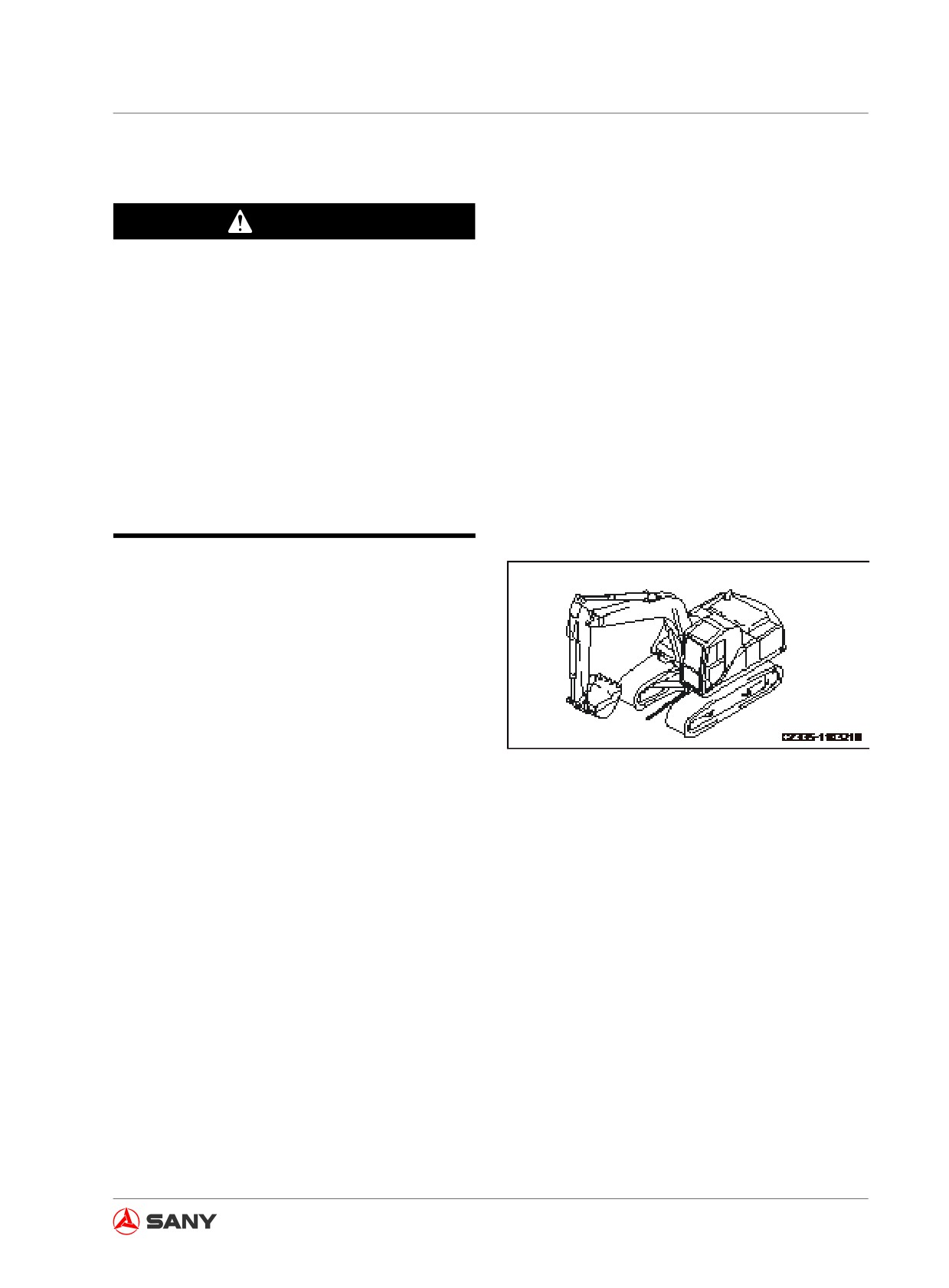
Fig.
6-9
6-14
Troubleshooting
6.4 Towing Hook for Light Loads
WARNING
● Towing the machine improperly could
cause severe accidents. The following
items must be observed when towing
the machine.
● Shackle must be used.
● Keep the wire cable parallel to the
ground and align its direction with that
of the track frame.
● Move the machine slowly and avoid im-
posing sudden load on wire cable.
The track frame has an eye, which can be
hooked when towing a light object.
Fig. 6-10
6.5 Severe Operating Conditions
● When performing excavation in water, if the
installation pins of work tool go below wa-
ter surface, it is necessary to add grease
to the pins before each operation.
● For heavy-loaded operation and deep ex-
cavation, it is necessary to add grease to
the installation pins of the work tool before
each operation. Cycle the operation of the
boom, stick and bucket for several times
before refilling the grease.
6-15
Troubleshooting
6.6 Engine Failures
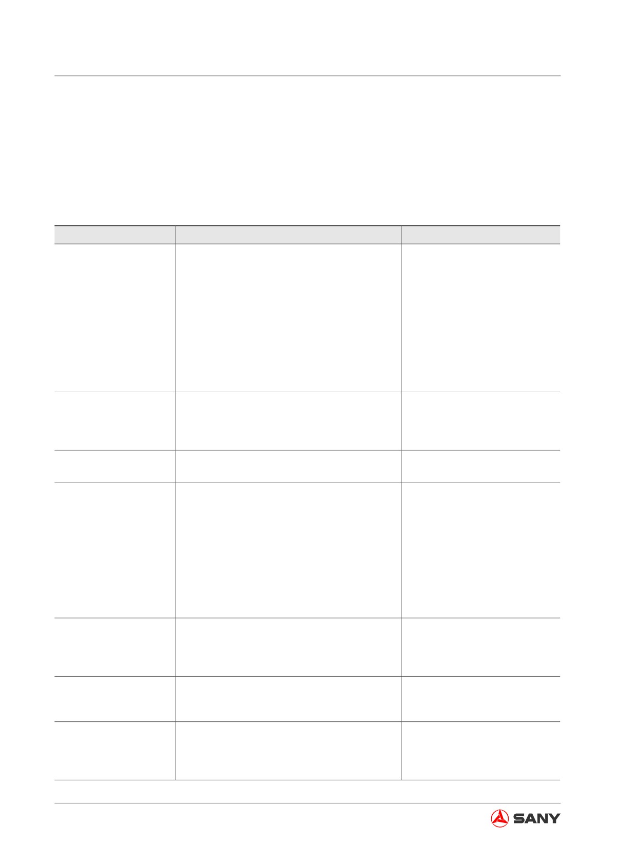
6.6.1 Engine troubleshooting table
Check the engine according to the following table if any failure occurs to it. Contact your Sany
distributor to repair the engine.
Failure
Causes
Remedy
●
Recharge/replace the bat-
●
Battery low
tery.
●
Engine start switch internal failure
●
Replace
●
Pilot switch failure
●
Repair/replace
●
Start motor failure
●
Repair/replace
Unable to start the en-
●
Open circuit of wire harness
●
Check/repair
gine
●
Fuse failure (F1)
●
Replace
●
Short circuit of wire (grounding failure)
●
Check/repair
●
Alternator internal failure
●
Repair/replace
●
Start relay failure
●
Replace
●
Brake failure
●
Repair/replace
●
Open circuit of wire harness
●
Check/repair
●
Sensor internal failure
●
Replace
Rough engine speed
●
Short circuit of wire (grounding failure)
●
Check/repair
●
Sensor internal failure
●
Replace
Unable to power off the
●
Battery relay failure
●
Replace
machine
●
Breakdown of surge diode
●
Replace
●
Boom-up signal failure
●
Check/repair
●
Boom-down signal failure
●
Check/repair
●
Arm-in signal failure
●
Check/repair
●
Arm-out signal failure
●
Check/repair
●
Bucket-dig signal failure
●
Check/repair
Auto idle fails.
●
Bucket-dump signal failure
●
Check/repair
●
Swing signal failure
●
Check/repair
●
Travel signal failure
●
Check/repair
●
Attachment signal failure
●
Check/repair
●
Controller failure
●
Replace
●
Preheat fuse failure
●
Replace
●
Preheat relay failure
●
Replace
Preheating function fails.
●
Short circuit of wire (grounding failure)
●
Check/repair
●
Preheat controller failure
●
Replace
●
Hydraulic lockout control failure
●
Repair/replace
All devices fail.
●
Short circuit of wire (grounding failure)
●
Check/repair
●
Failure of internal coil of pilot lockout valve
●
Replace
●
Sensor failure
●
Replace
●
Short circuit of harness (grounding failure)
●
Check/repair
Boom slow and weak
●
Open circuit of harness
●
Check/repair
●
Controller failure
●
Replace
6-16
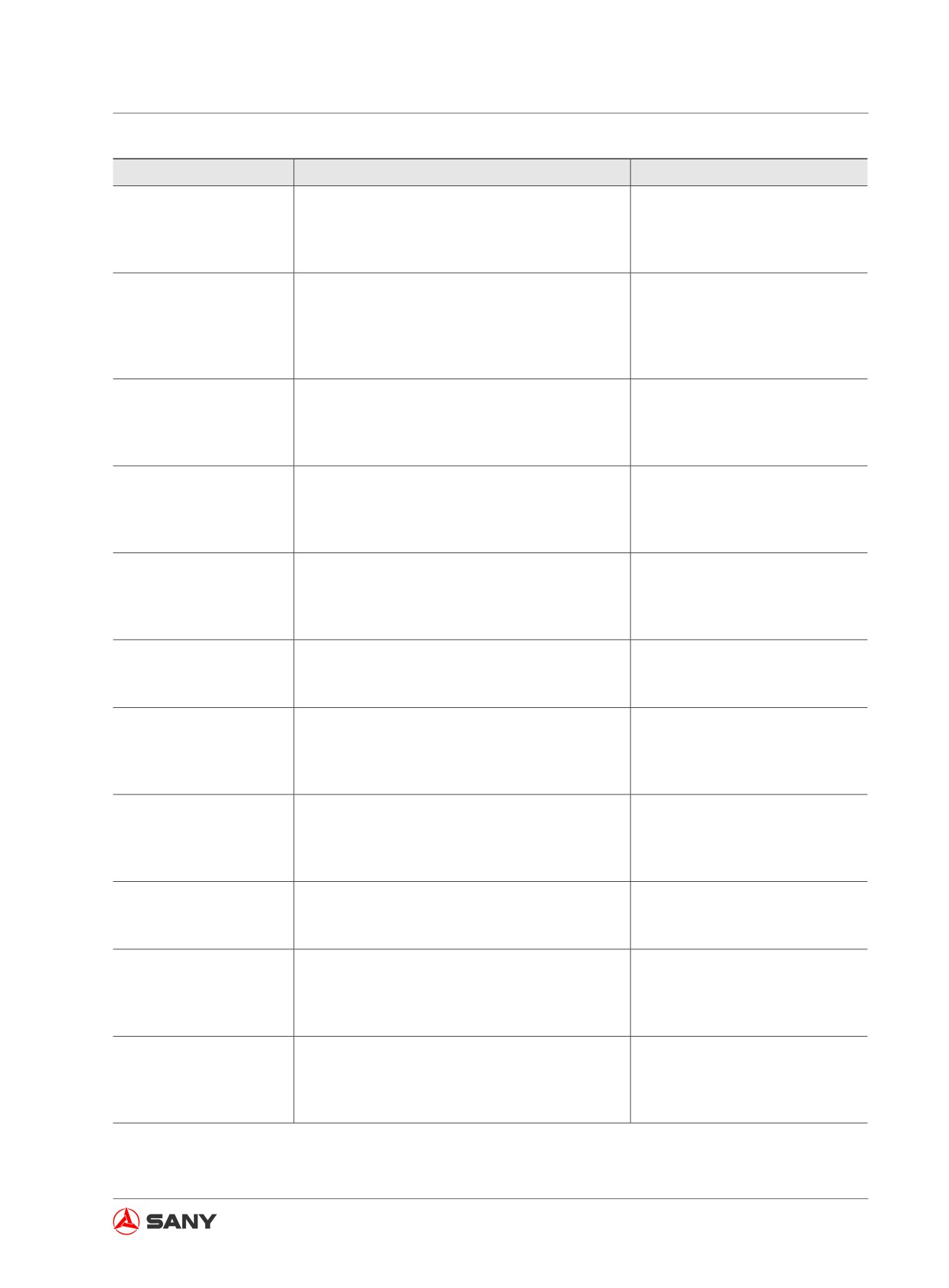
Troubleshooting
Failure
Causes
Remedy
●
Sensor failure
●
Replace
●
Short circuit of harness (grounding failure)
●
Check/repair
Arm slow and weak
●
Open circuit of harness
●
Check/repair
●
Controller failure
●
Replace
●
Sensor failure
●
Replace
●
Short circuit of harness (grounding failure)
●
Check/repair
Bucket slow and weak
●
Open circuit of harness
●
Check/repair
●
Bucket confluence solenoid valve failure
●
Replace
●
Controller failure
●
Replace
●
Sensor failure
●
Replace
●
Short circuit of harness (grounding failure)
●
Check/repair
Travel slow and weak
●
Open circuit of harness
●
Check/repair
●
Controller failure
●
Replace
●
Fuse failure
●
Replace
●
Open circuit of wire
●
Check/repair
Monitor black-out
●
Short circuit of wire (grounding failure)
●
Check/repair
●
Monitor failure
●
Replace
●
Resistor failure
●
Replace
●
Open circuit of wire
●
Check/repair
Monitor displays nothing.
●
Short circuit of wire (grounding failure)
●
Check/repair
●
Monitor or controller failure
●
Replace
●
Dual travel speed solenoid valve failure
●
Replace
Dual-travel speed failure
●
Open circuit of wire
●
Check/repair
●
Short circuit of wire (grounding failure)
●
Check/repair
●
Coolant temperature sensor failure
●
Replace
Engine coolant tempera-
●
Open circuit of wire
●
Check/repair
ture reading incorrect
●
Short circuit of wire (grounding failure)
●
Check/repair
●
Wire short-circuited with 24V
●
Check/repair
●
Fuel level sensor failure
●
Replace
Fuel level reading incor-
●
Open circuit of wire
●
Check/repair
rect
●
Short circuit of wire (grounding failure)
●
Check/repair
●
Wire short-circuited with 24V
●
Check/repair
●
Wiper motor internal failure
●
Repair/replace
Wiper failure
●
Open circuit of wire
●
Check/repair
●
Short circuit of wire (grounding failure)
●
Check/repair
●
5V power supply failure
●
Repair/replace
Arm-in pilot pressure
●
Open circuit of signal line
●
Check/repair
reading incorrect
●
Short circuit of signal line
●
Check/repair
●
Sensor failure
●
Replace
●
5V power supply failure
●
Repair/replace
Arm-out pilot pressure
●
Open circuit of signal line
●
Check/repair
reading incorrect
●
Short circuit of signal line
●
Check/repair
●
Sensor failure
●
Replace
6-17
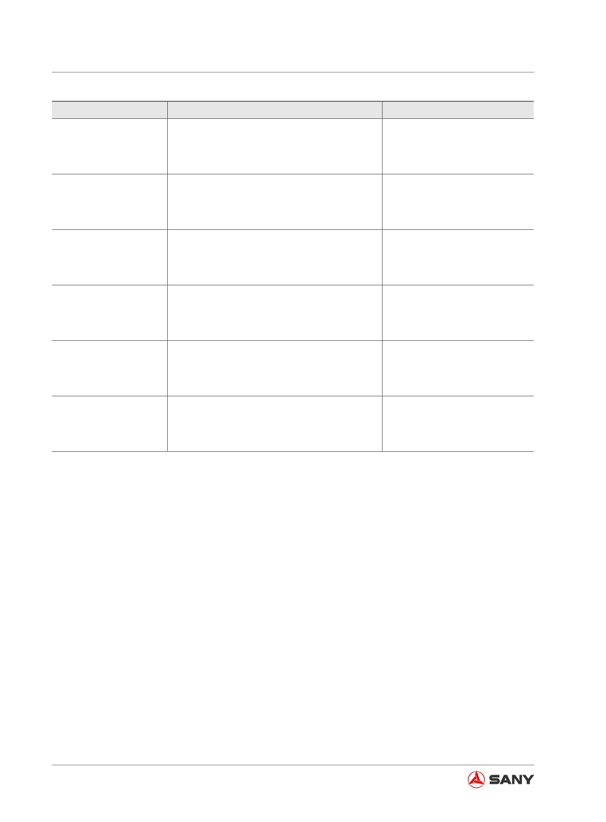
Troubleshooting
Failure
Causes
Remedy
●
5V power supply failure
●
Repair/replace
Boom-up pilot pressure
●
Open circuit of signal line
●
Check/repair
reading incorrect
●
Short circuit of signal line
●
Check/repair
●
Sensor failure
●
Replace
●
5V power supply failure
●
Repair/replace
Boom-down pilot pres-
●
Open circuit of signal line
●
Check/repair
sure reading incorrect
●
Short circuit of signal line
●
Check/repair
●
Sensor failure
●
Replace
●
5V power supply failure
●
Repair/replace
Bucket-dig pilot pressure
●
Open circuit of signal line
●
Check/repair
reading incorrect
●
Short circuit of signal line
●
Check/repair
●
Sensor failure
●
Replace
●
5V power supply failure
●
Repair/replace
Bucket-dump pilot pres-
●
Open circuit of signal line
●
Check/repair
sure reading incorrect
●
Short circuit of signal line
●
Check/repair
●
Sensor failure
●
Replace
●
5V power supply failure
●
Repair/replace
Swing pilot pressure
●
Open circuit of signal line
●
Check/repair
reading incorrect
●
Short circuit of signal line
●
Check/repair
●
Sensor failure
●
Replace
●
5V power supply failure
●
Repair/replace
Travel pilot pressure
●
Open circuit of signal line
●
Check/repair
reading incorrect
●
Short circuit of signal line
●
Check/repair
●
Sensor failure
●
Replace
Table 6-2
6-18
Troubleshooting
6.6.2 Coolant temperature high
CAUTION
● Never remove the radiator cap when the
coolant is still hot. Hot water or steam
may squirt and cause burns.
● Wait the coolant to cool down before re-
moving the radiator cap.
NOTICE
● Do not stop the engine immediately.
sudden rise of coolant temperature can
cause engine parts to burn.
● Refill the coolant slowly in several
times. Quick filling of low-temperature
coolant can cause engine cracks.
When the coolant temperature gauge shows
a temperature higher than 100°C, the coolant
temperature alert indicator will be on. Stop op-
erating your machine and keep engine running
at a speed a little higher than idle in order to
reduce temperature. When the pointer of cool-
ant temperature gauge returns to the middle
position, the alert indicator is off. Now, stop the
engine and perform the following steps.
6-19
Troubleshooting
Always prepare your machine as required and
lock out/tag out your machine before proceed-
ing. See “Preparing the machine” on page
2-58 and “Lock-out and tag-out” on page
2-60.
1. Check radiator hoses for coolant leak.
2. Check V-belt for rupture. Check the belt
tension.
3. Check coolant level. Refill coolant if neces-
sary.
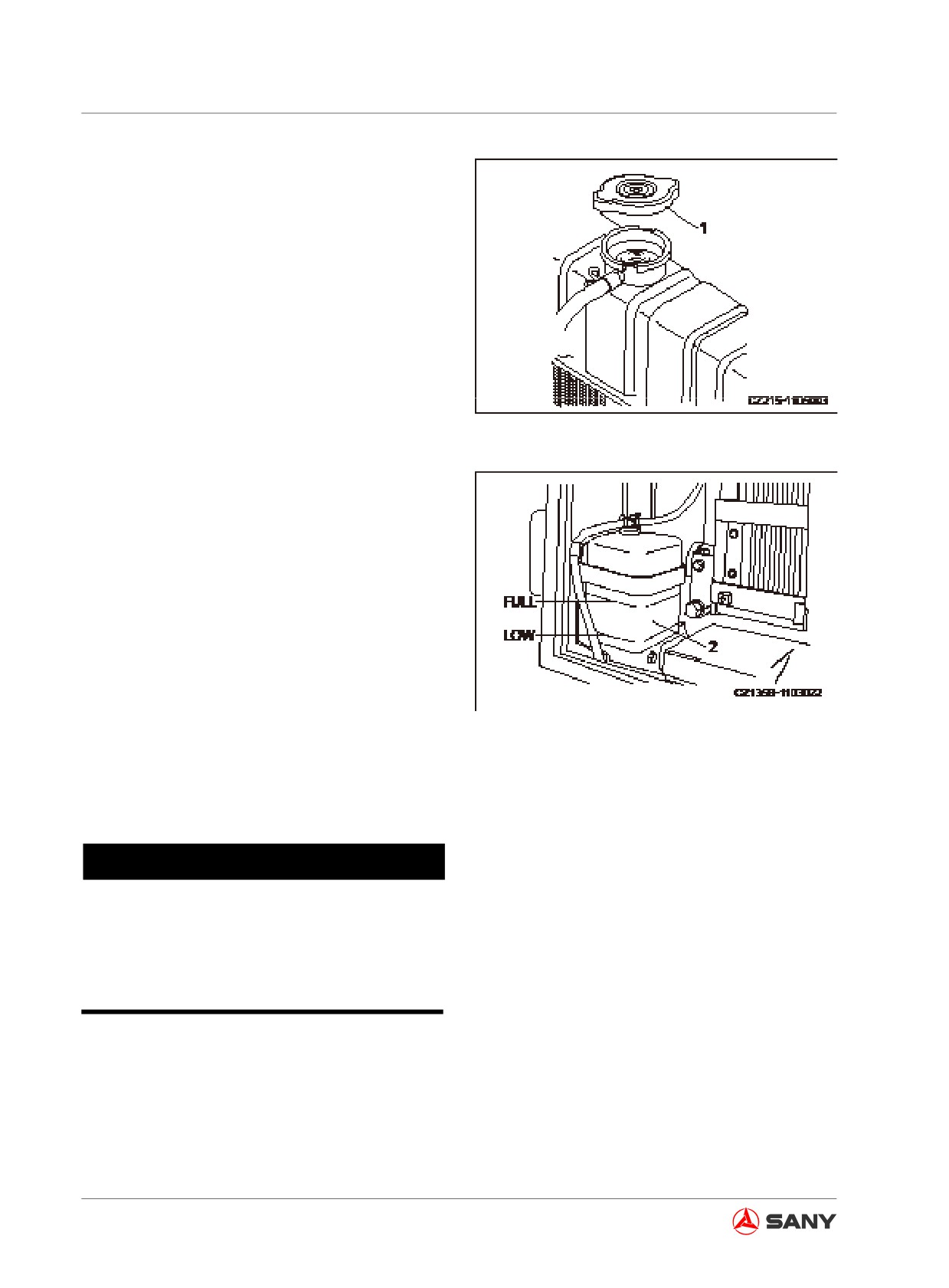
Fig. 6-11
● Remove the radiator cap (1) and refill
coolant to the opening. Tighten the cap
properly.
● Open the reservoir (2) and refill coolant
to the FULL mark. Tighten the cap prop-
erly.
4. Check the front of radiator for any contami-
nants.
5. If your machine has coolant leak or often
encounters higher coolant temperature, the
cooling system has a problem.
Fig. 6-12
6.6.3 Engine oil pressure low
NOTICE
When oil pressure low alert indicator is on,
shut down the engine immediately. Dam-
age could occur to the engine if leave it
running.
When the engine is just started, the oil pres-
sure gauge indicates high pressure before the
engine is preheated. Check oil pressure after
the engine is fully preheated.
When engine oil pressure gauge shows a val-
ue lower than the one given in the following ta-
6-20
Troubleshooting
ble, the low oil pressure alert indicator and oil
filter alert indicator will be on at the same time,
altering that oil pressure is abnormal. Stop
operating your machine, shut down the engine
immediately, and proceed as the following.
Always prepare your machine as required and
lock out/tag out your machine before proceed-
ing. See “Preparing the machine” on page
2-58 and “Lock-out and tag-out” on page
2-60.
1. Check for oil leak.
2. Check engine oil level. Refill oil when
required.
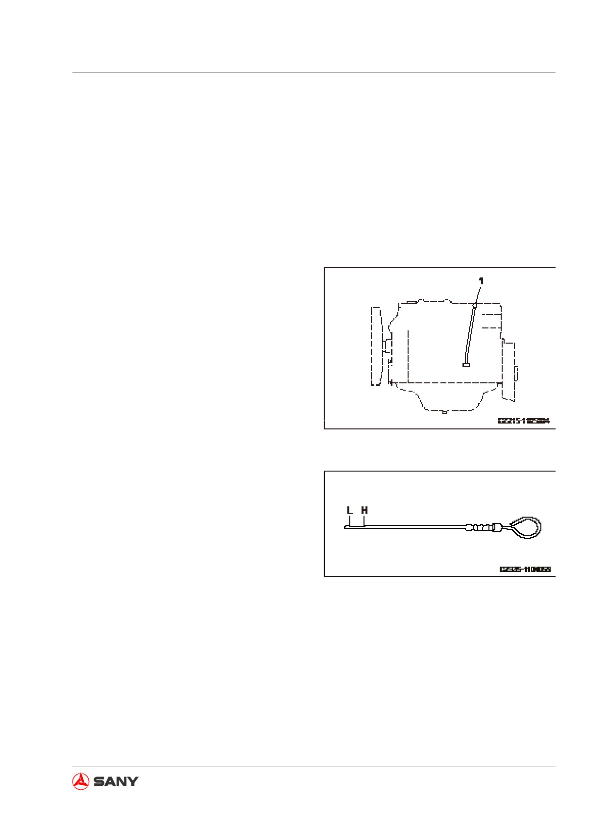
● Remove the dipstick (1). Wipe off the oil
on dipstick(1) with cloth.
● Fully insert the dipstick into oil and then
slowly pull it out.
● If oil level between the marks L and H,
the amount of oil is good.
Fig.
6-13
● If oil level is low, refill it immediately. If
engine oil is contaminated, change the
oil immediately.
● Replace the dipstick(1) after checking.
3. If engine oil level is normal but abnormal
pressure of engine oil is altered, contact
your Sany distributor in time to solve the
problem.
Fig.
6-14
6-21
Troubleshooting
6.6.4 When fuel exhausts
When fuel exhausts, it is necessary to refuel
the engine and purge air from the fuel system
before restarting it.
WARNING
● Never use a lighter, smoke, or use other
fire sources when purging the air. A fire
source can cause fire.
● Completely remove engine oil or fuel
splashed onto the exhaust pipe and
other places. These oil and fuel can
cause fire or slipping accident.
● The space for air-purging operation is
limited. Take care not to be cut by the
edges.
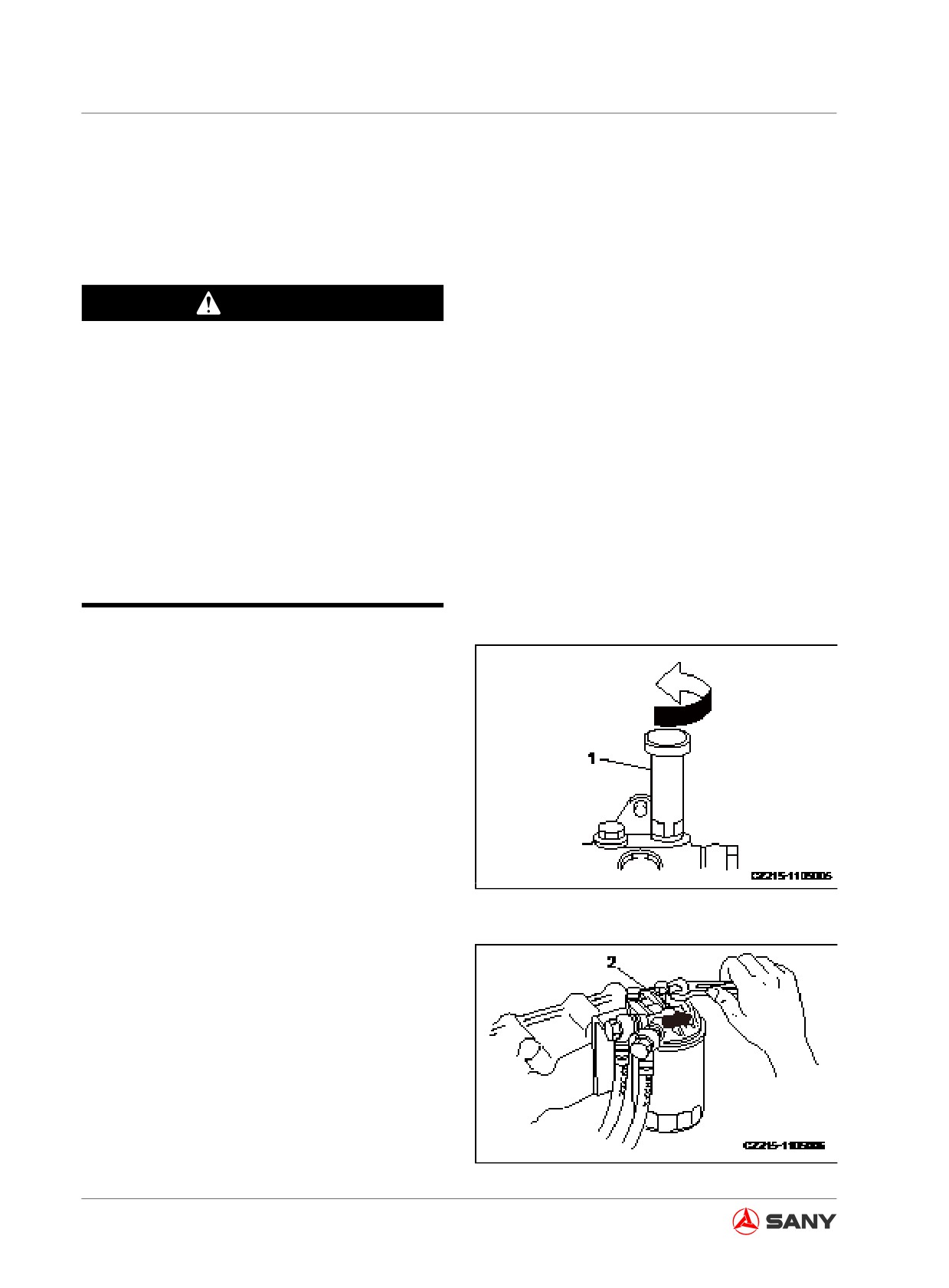
1. Turn counterclockwise the handle (1) of
manual pump to release it.
Fig. 6-15
2. Loosen air vent plug (2) on fuel filter and
cover it with cloth.
Fig. 6-16
6-22
Troubleshooting
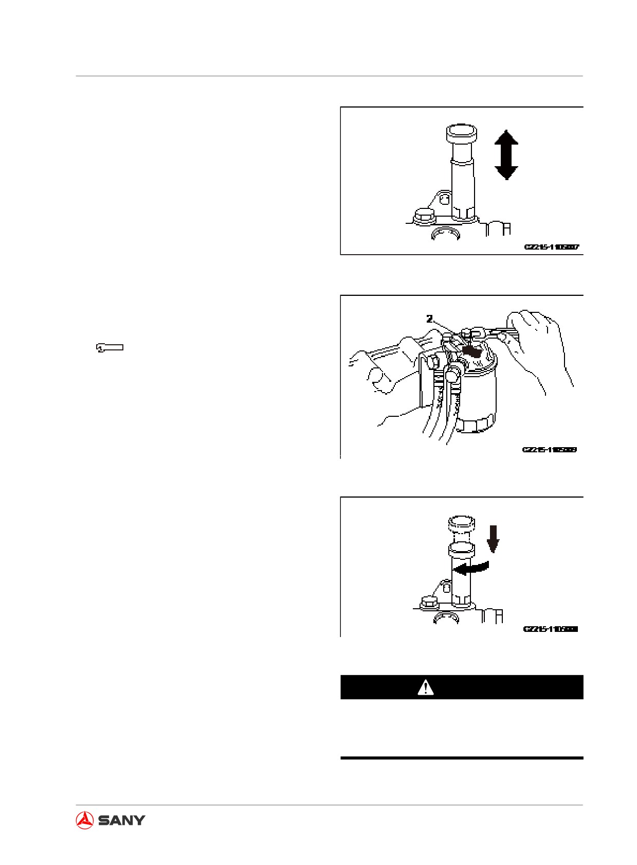
3. Repeatedly push the pump to transfer fuel
until no foam is seen at the vent.
Fig. 6-17
4. Retighten plug (2) when you are sure no
foam is seen.
Plug tightening torque:
9.8±2.0N·m {1±0.2 kgf·m}
Fig. 6-18
5. Continue to operate the manual pump until
heavy resistance is felt.
Resistance of pump operation may not rise
when fuel temperature is low. It is neces-
sary to operate the pump continuously and
repeatedly.
Fig. 6-19
6. After purging the air, completely remove
WARNING
splashed fuel before starting the engine.
Make sure no fuel leaks from filter and its
7. Make sure no fuel leaks.
housing. Fuel leak could cause fire.
6-23
Troubleshooting
6.6.5 When engine rotates reversely
WARNING
Reverse rotation of engine can burn the
engine within several minutes or cause
severe injury. Shut down the engine imme-
diately once reverse rotation is found. The
exhaust gas from air cleaner is possible to
cause fire.
The following symptoms can be used to iden-
tify reverse rotation of engine.
● High colliding sound produced after start-
ing
● Heavy smoke coming out air cleaner
● Tachometer and oil pressure gauge giving
no response
● Low oil pressure alert indicator on
Check and clean the air cleaner and intake
hoses after shutting down the engine. Replace
any defective air cleaner or hose immediately.
6-24
Troubleshooting
6.7 Failures of the Electrical System
6.7.1 Electrical system troubleshooting table
Trouble-shoot the electrical system according to the following tables. Contact your Sany distribu-
tor solve the problem.
Failure
Causes
Remedy
●
Recharge/replace the bat-
●
Battery low
tery.
●
Engine start switch internal failure
●
Replace
●
Pilot switch failure
●
Repair/replace
●
Start motor failure
●
Repair/replace
Unable to start the en-
●
Open circuit of wire harness
●
Check/repair
gine
●
Fuse failure (F1)
●
Replace
●
Short circuit of wire (grounding failure)
●
Check/repair
●
Alternator internal failure
●
Repair/replace
●
Start relay failure
●
Replace
●
Brake failure
●
Repair/replace
●
Open circuit of wire harness
●
Check/repair
●
Sensor internal failure
●
Replace
Rough engine speed
●
Short circuit of wire (grounding failure)
●
Check/repair
●
Sensor internal failure
●
Replace
Unable to power off the
●
Battery relay failure
●
Replace
machine
●
Breakdown of surge diode
●
Replace
●
Boom-up signal failure
●
Check/repair
●
Boom-down signal failure
●
Check/repair
●
Arm-in signal failure
●
Check/repair
●
Arm-out signal failure
●
Check/repair
●
Bucket-dig signal failure
●
Check/repair
Auto idle fails.
●
Bucket-dump signal failure
●
Check/repair
●
Swing signal failure
●
Check/repair
●
Travel signal failure
●
Check/repair
●
Attachment signal failure
●
Check/repair
●
Controller failure
●
Replace
●
Preheat fuse failure
●
Replace
●
Preheat relay failure
●
Replace
Preheating function fails.
●
Short circuit of wire (grounding failure)
●
Check/repair
●
Preheat controller failure
●
Replace
●
Hydraulic lockout control failure
●
Repair/replace
All devices fail.
●
Short circuit of wire (grounding failure)
●
Check/repair
●
Failure of internal coil of pilot lockout valve
●
Replace
●
Sensor failure
●
Replace
●
Short circuit of harness (grounding failure)
●
Check/repair
Boom slow and weak
●
Open circuit of harness
●
Check/repair
●
Controller failure
●
Replace
6-25
Troubleshooting
Failure
Causes
Remedy
●
Sensor failure
●
Replace
●
Short circuit of harness (grounding failure)
●
Check/repair
Arm slow and weak
●
Open circuit of harness
●
Check/repair
●
Controller failure
●
Replace
●
Sensor failure
●
Replace
●
Short circuit of harness (grounding failure)
●
Check/repair
Bucket slow and weak
●
Open circuit of harness
●
Check/repair
●
Bucket confluence solenoid valve failure
●
Replace
●
Controller failure
●
Replace
●
Sensor failure
●
Replace
●
Short circuit of harness (grounding failure)
●
Check/repair
Travel slow and weak
●
Open circuit of harness
●
Check/repair
●
Controller failure
●
Replace
●
Fuse failure
●
Replace
●
Open circuit of wire
●
Check/repair
Monitor black-out
●
Short circuit of wire (grounding failure)
●
Check/repair
●
Monitor failure
●
Replace
●
Resistor failure
●
Replace
●
Open circuit of wire
●
Check/repair
Monitor displays nothing.
●
Short circuit of wire (grounding failure)
●
Check/repair
●
Monitor or controller failure
●
Replace
●
Dual travel speed solenoid valve failure
●
Replace
Dual-travel speed failure
●
Open circuit of wire
●
Check/repair
●
Short circuit of wire (grounding failure)
●
Check/repair
●
Coolant temperature sensor failure
●
Replace
Engine coolant tempera-
●
Open circuit of wire
●
Check/repair
ture reading incorrect
●
Short circuit of wire (grounding failure)
●
Check/repair
●
Wire short-circuited with 24V
●
Check/repair
●
Fuel level sensor failure
●
Replace
Fuel level reading incor-
●
Open circuit of wire
●
Check/repair
rect
●
Short circuit of wire (grounding failure)
●
Check/repair
●
Wire short-circuited with 24V
●
Check/repair
●
Wiper motor internal failure
●
Repair/replace
Wiper failure
●
Open circuit of wire
●
Check/repair
●
Short circuit of wire (grounding failure)
●
Check/repair
●
5V power supply failure
●
Repair/replace
Arm-in pilot pressure
●
Open circuit of signal line
●
Check/repair
reading incorrect
●
Short circuit of signal line
●
Check/repair
●
Sensor failure
●
Replace
●
5V power supply failure
●
Repair/replace
Arm-out pilot pressure
●
Open circuit of signal line
●
Check/repair
reading incorrect
●
Short circuit of signal line
●
Check/repair
●
Sensor failure
●
Replace
6-26
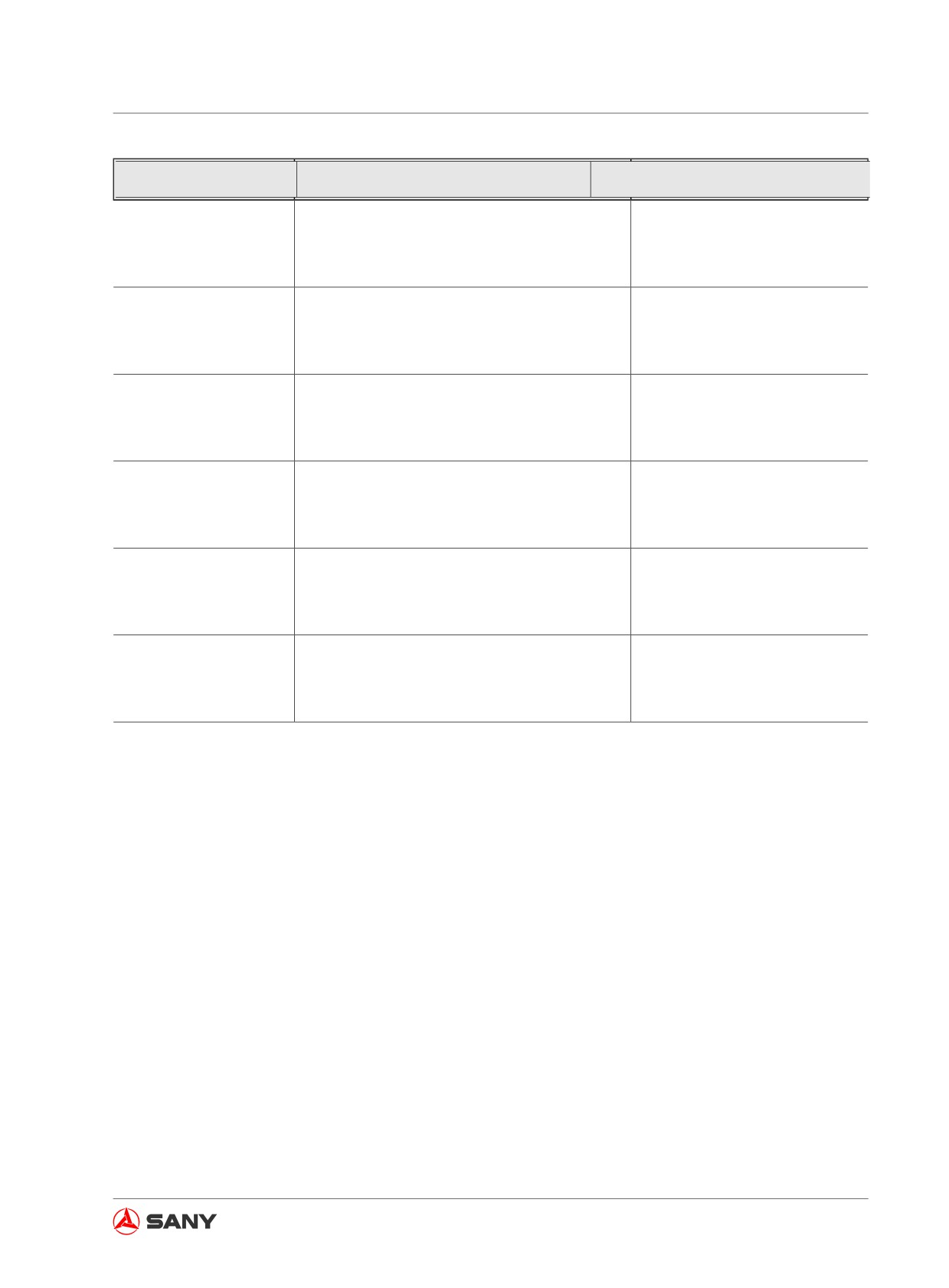
Troubleshooting
Failure
Causes
Remedy
●
5V power supply failure
●
Repair/replace
Boom-up pilot pressure
●
Open circuit of signal line
●
Check/repair
reading incorrect
●
Short circuit of signal line
●
Check/repair
●
Sensor failure
●
Replace
●
5V power supply failure
●
Repair/replace
Boom-down pilot pres-
●
Open circuit of signal line
●
Check/repair
sure reading incorrect
●
Short circuit of signal line
●
Check/repair
●
Sensor failure
●
Replace
●
5V power supply failure
●
Repair/replace
Bucket-dig pilot pressure
●
Open circuit of signal line
●
Check/repair
reading incorrect
●
Short circuit of signal line
●
Check/repair
●
Sensor failure
●
Replace
●
5V power supply failure
●
Repair/replace
Bucket-dump pilot pres-
●
Open circuit of signal line
●
Check/repair
sure reading incorrect
●
Short circuit of signal line
●
Check/repair
●
Sensor failure
●
Replace
●
5V power supply failure
●
Repair/replace
Swing pilot pressure
●
Open circuit of signal line
●
Check/repair
reading incorrect
●
Short circuit of signal line
●
Check/repair
●
Sensor failure
●
Replace
●
5V power supply failure
●
Repair/replace
Travel pilot pressure
●
Open circuit of signal line
●
Check/repair
reading incorrect
●
Short circuit of signal line
●
Check/repair
●
Sensor failure
●
Replace
Table 6-3
6-27
Troubleshooting
6.7.2 Failure codes
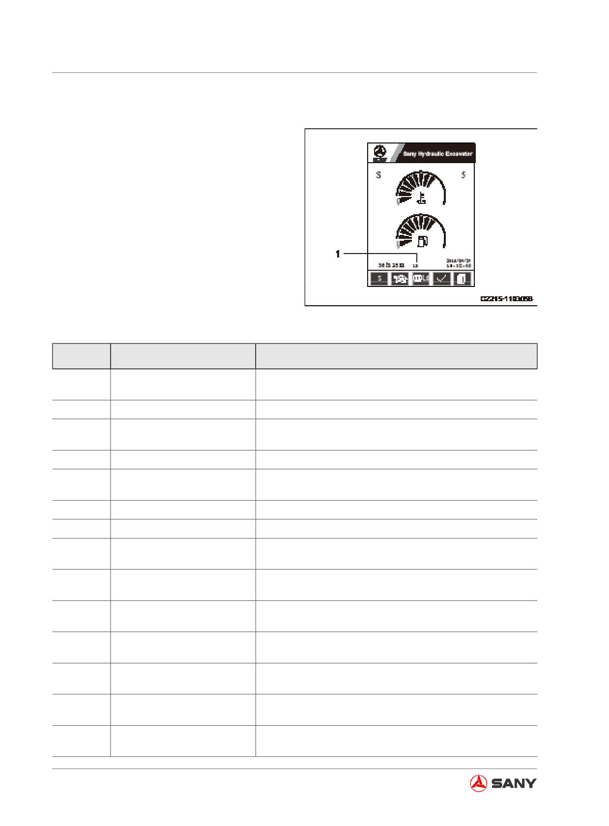
The failure code(1) displayed on the monitor
can be used to make failure analysis.
Fig. 6-20
Failure
Symptom
Alarm Trigger Condition
Code
Oil pressure lower than 200 and engine speed higher than
3
Engine oil pressure low
800 for 15s
4
Fuel level low
Fuel level lower than 10% for 10s
Coolant temperature higher than 105°C or coolant tempera-
5
Coolant temperature high
ture over-high pressure switch off
6
Air cleaner plugged
Air cleaner plugging pressure switch off
Engine speed lower than 800 rpm but higher than 400 rpm
7
Engine speed low
for 3s
8
Engine speed high
Engine speed higher than 2500 rpm
10
Hydraulic oil temperature high
Hydraulic oil temperature higher than 90°C for 10s
Motor feedback voltage lower than 0.25V or higher than 4.75V
12
Motor working range irregular
for 3s
Front pump pressure sensor
Front pump pressure collecting volt lower than 0.25V or
20
abnormal
higher than 4.75V for 3s
Rear pump pressure sensor
Rear pump pressure collecting volt lower than 0.25V or high-
21
abnormal
er than 4.75V for 3s
Bucket-dig pilot pressure sen-
Bucket-dig pilot pressure collecting volt lower than 0.25V or
22
sor abnormal
higher than 4.75V for 3s
Bucket-dump pilot pressure
Bucket-dig pilot pressure collecting volt lower than 0.25V or
23
sensor abnormal
higher than 4.75V for 3s
Arm-in pilot pressure sensor
Arm-in pilot pressure collecting volt lower than 0.25 and
24
abnormal
higher than 4.75 for 3s
Arm-out pilot pressure sensor
Arm-out pilot pressure collecting volt lower than 0.25 and
25
abnormal
higher than 4.75 for 3s
6-28
Troubleshooting
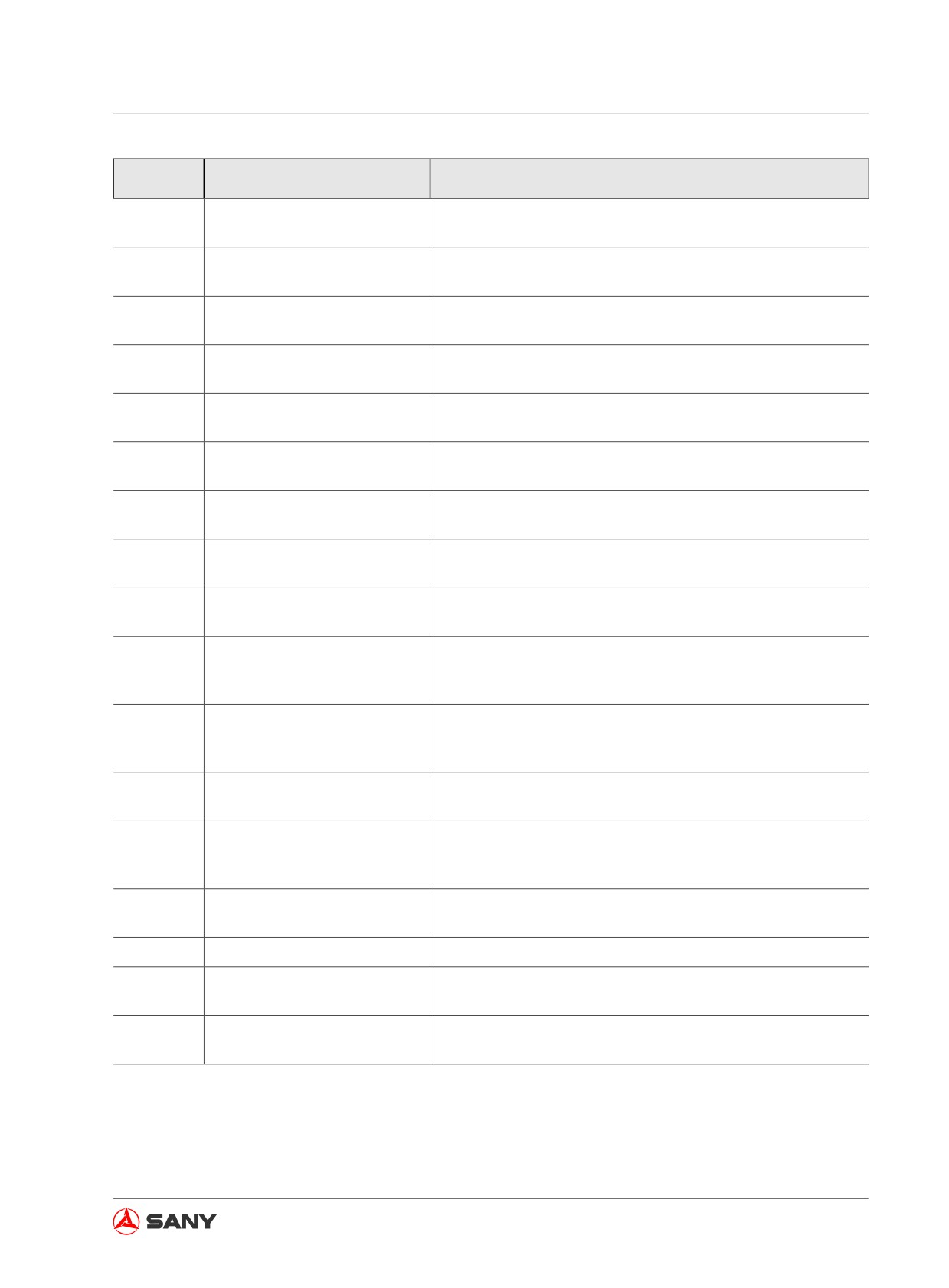
Failure
Symptom
Alarm Trigger Condition
Code
Boom-up pilot pressure sensor
Boom-up pilot pressure collecting volt lower than 0.25 and
26
abnormal
higher than 4.75 for 3s
Boom-down pilot pressure sen-
Boom-down pilot pressure collecting volt lower than 0.25 and
27
sor abnormal
higher than 4.75 for 3s
Left travel pilot pressure sensor
Left travel pilot pressure collecting volt lower than 0.25 and
28
abnormal
higher than 4.75 for 3s
Right travel pilot pressure sen-
Right travel pilot pressure collecting volt lower than 0.25 and
29
sor abnormal
higher than 4.75 for 3s
Swing pilot pressure sensor
Swing pilot pressure collecting volt lower than 0.25 and high-
30
abnormal
er than 4.75 for 3s
Front pump proportional valve
Front pump proportional valve current higher than 1300mA
34
overcurrent
for 3s
Rear pump proportional valve
Rear pump proportional valve current higher than 1300mA for
35
overcurrent
3s
Front pump proportional valve
Front pump proportional valve current lower than 200mA for
36
undercurrent
3s and controller PWM output higher than 10V
Rear pump proportional valve
Rear pump proportional valve current lower than 200mA for
37
undercurrent
3s and controller PWM output higher than 10V
Front pump proportional valve feedback current lower than
38
Front pump proportional valve
150mA or higher than 1350mA for 3s and controller PWM
duty output higher than 10V
Rear pump proportional valve feedback current lower than
39
Rear pump proportional valve
150mA or higher than 1350mA for 3s and controller PWM
duty output higher than 10V
Hydraulic oil temperature sen-
Hydraulic oil temperature collecting volt lower than 0.25V or
40
sor abnormal
higher than 4.75V for 3s
Coolant temperature collecting resistance lower than 10Ω or
41
Coolant sensor abnormal
higher than 120 Ω for 3s after 30 minutes since engine start-
ing
Fuel level collecting resistance lower than 10Ω or higher than
42
Fuel level sensor abnormal
120 Ω for 3s
43
Speed sensor abnormal
Speed collecting frequency lower than 100 for 3s under load
Fuel control dial collecting volt lower than 0.25V or higher
44
Fuel control dial abnormal
than 4.75V for 3s
CAN communication monitoring component overtime or reset
45
CAN bus abnormal
characters changed for 3s
Table 6-4
6-29
Troubleshooting
6.8 Battery
WARNING
●
It is dangerous to charge a battery
while it is installed on the machine. Re-
move the battery before charging it.
●
Stop the engine and turn the start
switch key to OFF position before
checking or handling the battery.
●
Wear goggles and rubber gloves when
handling the battery.
●
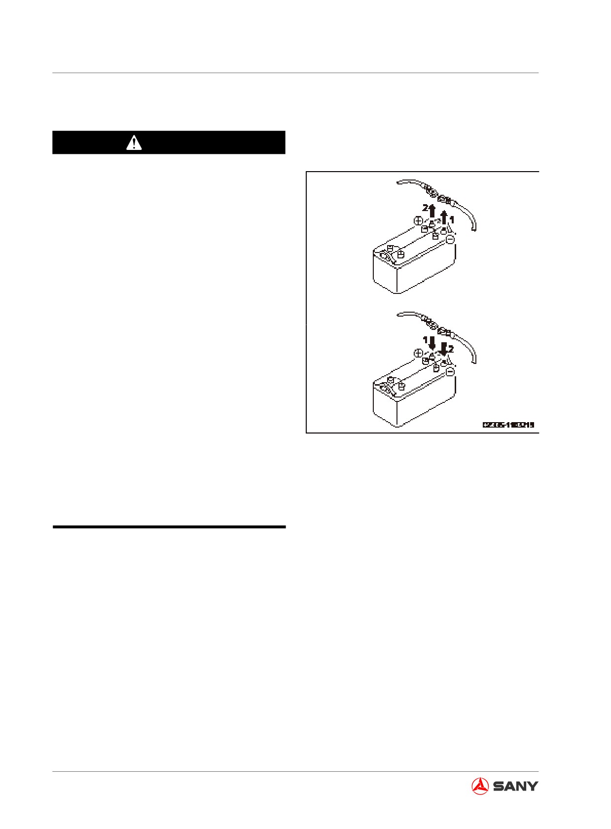
Disconnect first the grounding cable
(negative terminal (-)) before removing
the battery. Connect first the positive
terminal (+) while installing the bat-
tery. Be especially careful with your
tools, which may produce sparks when
touching the positive terminals and the
chassis.
●
A loose terminal can result in improper
contact, which may cause sparks and
Fig.
6-21
explosion.
●
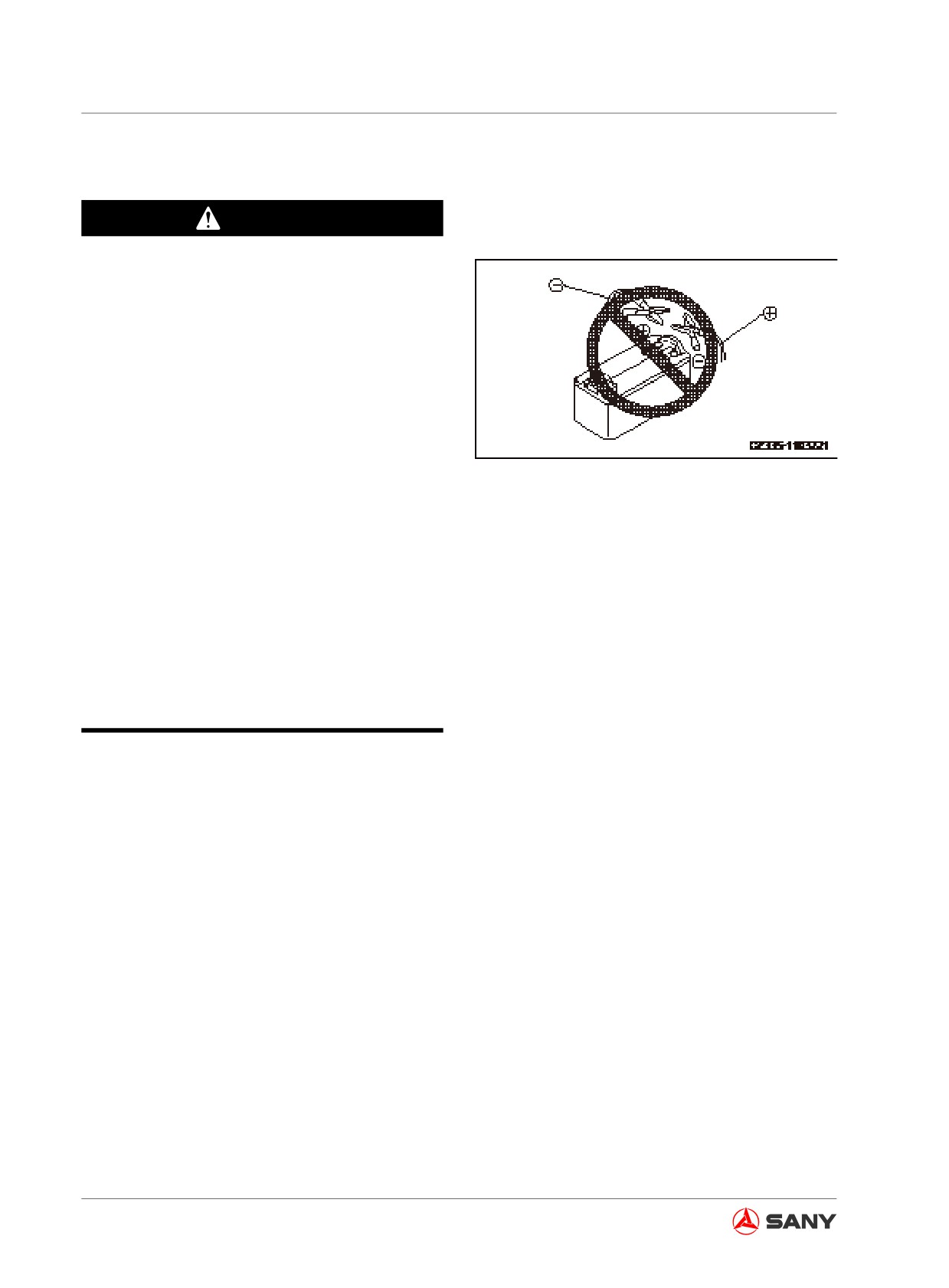
Check that which terminal is positive
(+) and which one is negative (-) when
removing or installing the terminals.
6.8.1 Battery removal and installation
● Disconnect the grounding cable (generally
the one in connection with the negative ter-
minal (-)) before removing the battery.
● Sparks can occur if your tool touches the
positive terminal and the chassis.
● Secure the battery with clamping plates
when changing the battery.
6-30
Troubleshooting
6.8.2 Battery charging
Improper handling can result in explosion
when the battery is charged. Follow the in-
struction, see“Battery”on page 6-30 and the
instruction of charger, and proceed the proce-
dure below:
●
Regulate the charger to the voltage appli-
cable to the battery. Incorrect voltage can
over heat the charger and cause explo-
sion.
Fig.
6-22
●
Connect the charger's positive clip (+) to
the battery's positive terminal (+). Connect
the charger's negative clip (-) to the bat-
tery's negative terminal (-). The wire clips
must be fixed.
●
Regulate the charging current to 1/10 of
the rated capacity of battery. In case of
quick charging, regulate the charging cur-
rent to a level below the rated capacity of
battery. Larger charging current may cause
leakage or evaporation of electrolyte,
hence fire and explosion.
●
If the battery electrolyte freezes, do not
charge the battery, or use an alternate
power supply to start the engine. Charging
a frozen battery may cause electrolyte to
catch on fire and the battery to explode.
6-31
Troubleshooting
6.8.3 Jump-starting the engine
WARNING
●
Never let the positive terminal (+) con-
tact with the negative terminal (-) when
connecting the cable.
●
Keep a normal machine away from
the faulty machine in order to prevent
sparks around the battery from burning
the hydrogen released from the battery.
●
Avoid mistakes in connection of the
jumper cable. Its final connection with
Fig.
6-23
upper structure of the machine can
produce sparks. In this case, the bat-
tery shall be connected to a location
that is far enough from the battery. (But
the work tool shall be excluded as the
work tool is not a good conductor.)
●
When removing the jumper cables, pay
extra attention to the cables, whose
clips shall not contact with each other
or with the chassis.
Note:
● The start system of the machine is sup-
plied with a 24V power source. Two 12V
batteries are connected serially to supply
power to a normally-operating machine.
● The sizes of jumper cables and clips shall
match the size of battery.
● Generally, the batteries of the machine
shall have the same capacity with the en-
gine to be started.
● Check the cables and clips for damage or
corrosion.
● Make sure that the cables and clips are
connected securely.
● Check both machines whether their lock-
out controls and brake levers are in the
6-32
Troubleshooting
"LOCKED" position.
● Check the control levers whether they are
in the neutral position.
6.8.3.1 Connecting the jumper cables
Turn the start switches of the normal machine
and the faulty machine to the OFF position.
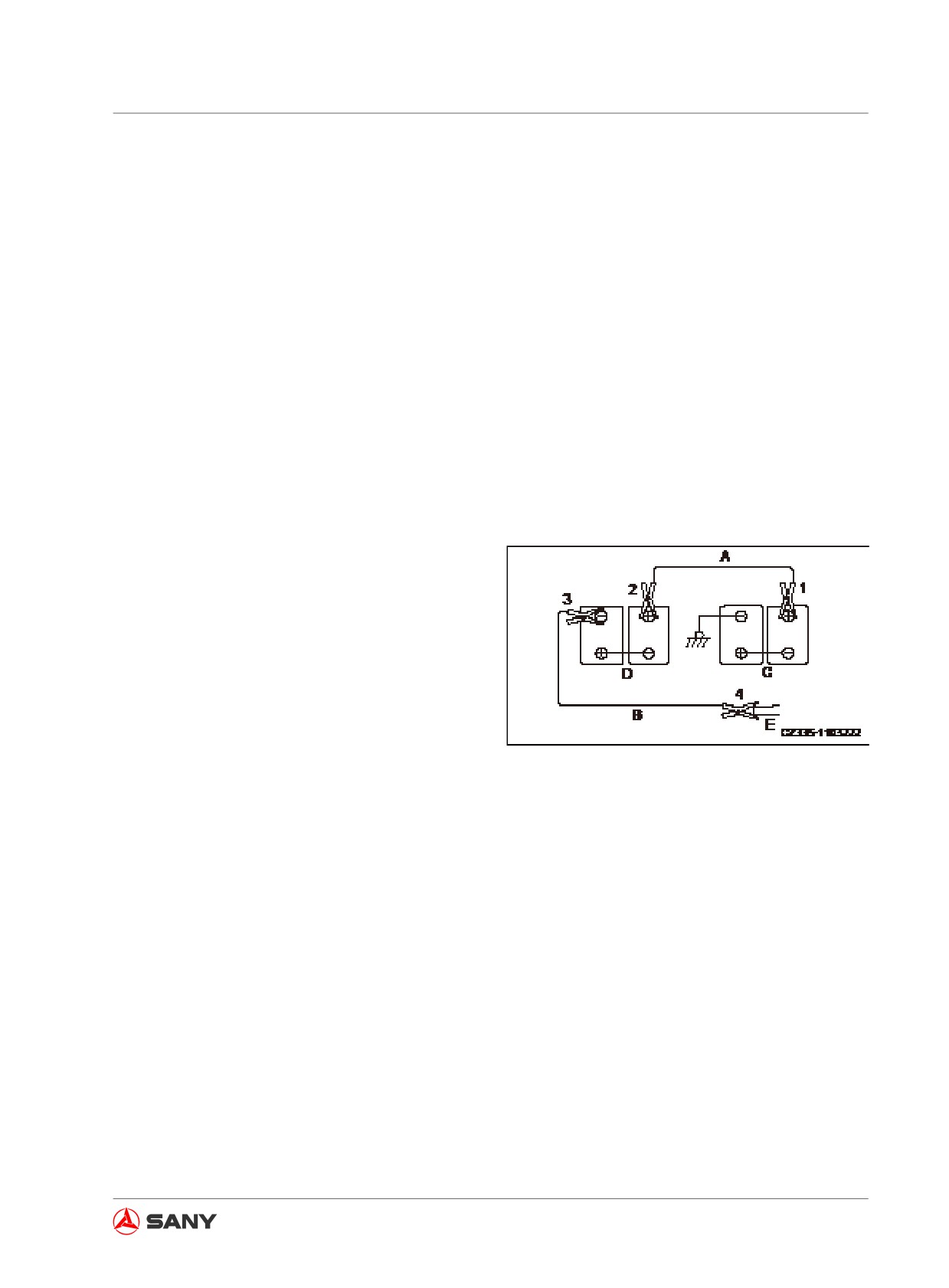
Connect the jumper cables in the numbered
sequence, as shown in the diagram.
1. Connect the clip of jumper cable (A) to the
positive terminal (+) of battery (C) of the
faulty machine.
2. Connect the clip on the other end of jumper
cable (A) to the positive terminal (+) of bat-
tery (D) of the normal machine.
3. Connect the clip of jumper cable (B) to the
negative terminal of battery (D) of the nor-
mal machine.
4. Connect the clip on the other end of jumper
cable (B) to the swivel frame (E) of the faulty
Fig.
6-24
machine.
6-33
Troubleshooting
6.8.3.2 Starting the engine
WARNING
Check the lockout control, which must
be in the "LOCKED" position regardless
of that the machine is operating normally
or has trouble. Check all control levers,
which shall be in the "retaining" or neutral
position.
1. Make sure the clips are securely connected
with terminals of the battery.
2. Start the engine of the good machine and
run it at high idle.
3. Turn the start switch of the faulty machine
to "START" position and start the engine.
If the engine fails to start, wait for two minutes
before attempting to restart it.
6.8.3.3 Disconnecting the jumper cables
After the engine is started, disconnect the
jumper cables in steps reversed to their con-
nection.
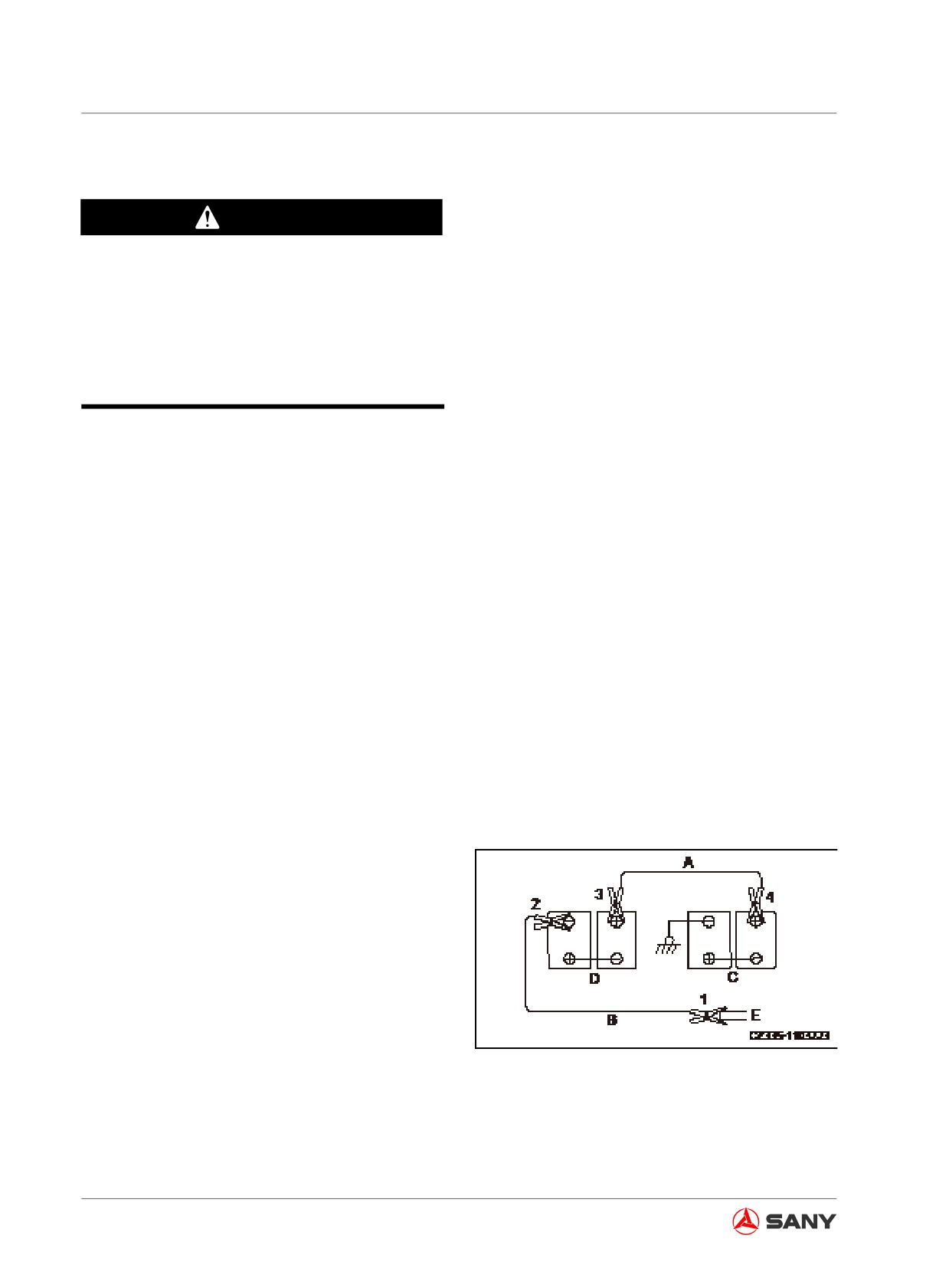
1. Disconnect the clip of the jumper cable (B)
from the swivel frame (E) of the faulty ma-
chine.
2. Disconnect the clip of the jumper cable (B)
from the negative terminal (-) of battery (D)
of the normal machine.
3. Disconnect the clip of jumper cable (A) from
the positive terminal (+) of battery (D) of the
Fig. 6-25
normal machine.
4. Disconnect the clip of jumper cable (A) from
the positive terminal (+) of battery (C) of the
faulty machine.
6-34
Troubleshooting
6.9 Failures of the Hydraulic System
● Trouble-shoot the hydraulic system according to the following tables. Contact your Sany dis-
tributor solve the problem.
● Set the working mode to S and the fuel control dial to position 10 before troubleshooting
Failure
Causes
Remedy
●
Bad adjustment or failure of main relief valve
●
Replace
●
Pilot relief valve failure
●
Replace
Work equipment moving
●
Regulator failure
●
Repair/replace
slowly, or travel and swing
●
Plunger pump failure
●
Check/repair
speed slow
●
Failure of pilot proportional solenoid valve of
●
Repair/replace
right joystick
●
Pilot safety valve failure
●
Repair/replace
Work equipment, final drive
●
Pilot pump relief valve failure
●
Replace
or swing drive not function-
●
Hydraulic pump failure
●
Check/repair
ing
●
Coupling failure
●
Check/repair
●
Hydraulic oil level low
●
Refill hydraulic oil
●
Bad hydraulic oil
●
Use suitable hyd oil
Abnormal noise in hydraulic
●
Hydraulic tank cap vent plugged
●
Clean/replace
pump
●
Hydraulic tank filter screen plugged
●
Clean/replace
●
Plunger pump failure
●
Check/repair
●
Sensor failure
●
Replace
Auto idle not functioning
●
Pilot valve failure
●
Replace
●
Controller failure
●
Repair/replace
●
Right pilot valve (boom circuit) failure
●
Check/repair
●
Pressure sensor failure
●
Replace
●
Boom control valve (spool) failure
●
Repair/replace
Boom speed slow
●
Boom control valve (retaining valve) failure
●
Repair/replace
●
Boom control valve (Safety valve and feed
●
Repair/replace
valve) seal failure
●
●
Boom cylinder failure
●
Check/repair
●
Left pilot valve (arm circuit) failure
●
Check/repair
●
Pressure sensor failure
●
Replace
●
Arm control valve (spool) failure
●
Repair/replace
Arm speed slow
●
Arm control valve (regeneration valve) failure
●
Repair/replace
●
Arm control valve (Safety valve and feed valve)
●
Repair/replace
or seal failure
●
●
Arm cylinder failure
●
Check/repair
●
Check/repair
●
Right pilot valve (bucket circuit) failure
●
Replace
●
Pressure sensor failure
●
Repair/replace
●
Bucket control valve (spool) failure
●
Repair/replace
Bucket speed slow
●
Bucket control valve (regeneration valve) failure
●
●
Bucket control valve (Safety valve and feed
●
Repair/replace
valve) or seal failure
●
●
Bucket cylinder failure
●
Check/repair
6-35
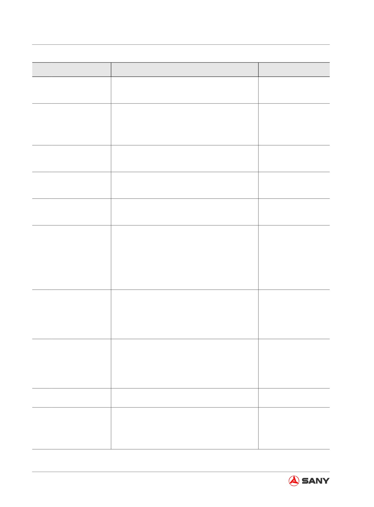
Troubleshooting
Failure
Causes
Remedy
●
Pilot valve failure
●
Check/repair
One cylinder of work equip-
●
Pressure sensor failure
●
Replace
ment not working
●
Work equipment control valve (spool) failure
●
Repair/replace
●
Work equipment cylinder failure
●
Repair/replace
●
Retaining valve (of boom or arm) failure
●
Repair/replace
Work equipment cylinder
●
Work equipment control valve (safety valve and
●
Repair/replace
drifting excessively
feed valve) seal failure
●
●
Work equipment valve spool failure
●
Repair/replace
●
Arm regeneration valve failure
●
Repair/replace
Work equipment sluggish
●
Control valve (safety valve and feed valve) fail-
●
Repair/replace
ure
Other work equipment
moves when single cylinder
●
Control valve seal failure
●
Replace
is in relief.
Travel speed drops remark-
ably during swing or travel
●
Straight travel valve failure
●
Repair/replace
operation.
●
Travel pilot valve failure
●
Repair/replace
●
Pilot relief valve failure
●
Replace
●
Regulator failure
●
Repair/replace
Machine runs out during
●
Proportional solenoid valve sluggish
●
Repair/replace
travel
●
Travel valve spool sluggish
●
Repair/replace
●
Central swivel joint sluggish
●
Repair/replace
●
Travel motor failure
●
Repair/replace
●
Travel pilot pressure sensor failure
●
Replace
●
Travel pilot valve failure
●
Repair/replace
●
Pilot relief valve failure
●
Replace
●
Sensor failure
●
Replace
Travel speed slow
●
Travel control valve (spool) failure
●
Repair/replace
●
Travel control valve (feed valve) failure
●
Repair/replace
●
Travel motor failure
●
Check/repair
●
Travel pilot valve failure
●
Repair/replace
●
Travel pilot pressure sensor failure
●
Replace
Machine steering difficult or
●
Travel control valve (spool) failure
●
Repair/replace
power insufficient
●
Travel control valve (feed) failure
●
Repair/replace
●
Travel motor (safety valve) failure
●
Repair/replace
●
Travel motor (check valve) failure
●
Repair/replace
●
High/low travel speed shift valve failure
●
Repair/replace
Unable to shift travel speed
●
Travel motor failure
●
Check/repair
●
Travel control valve (feed valve) seat failure
●
Repair/replace
●
Travel motor (safety valve) seat failure
●
Repair/replace
Travel fails (on one side)
●
Travel motor (feed valve) seat failure
●
Repair/replace
●
Travel motor failure
●
Check/repair
●
Pilot pressure sensor failure
●
Replace
6-36
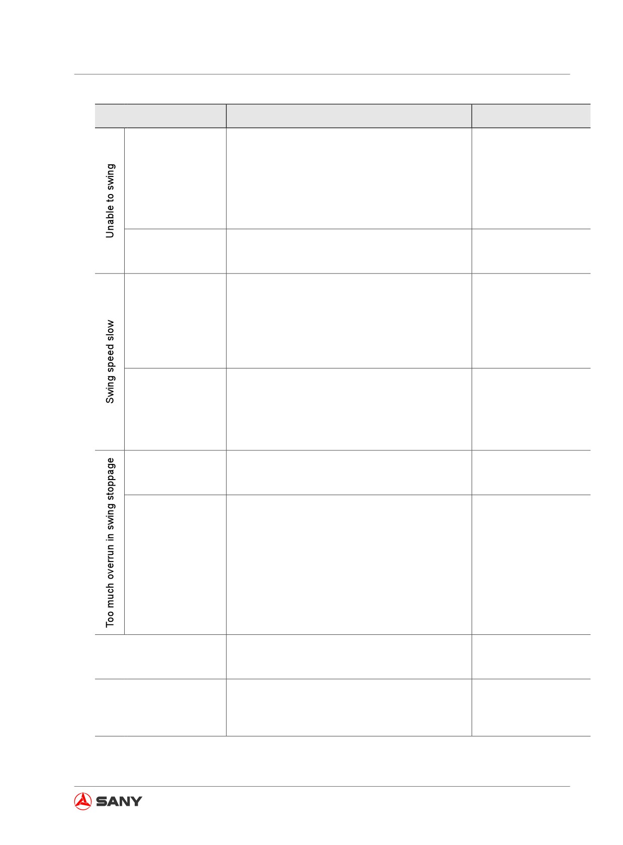
Troubleshooting
Failure
Causes
Remedy
●
Swing motor (parking brake) failure
●
Check/repair
●
Bad adjustment or failure of swing motor (safety
●
Adjust/replace
In both directions
valve)
●
●
Swing motor failure
●
Check/repair
●
Swing drive failure
●
Check/repair
●
Pilot valve failure
●
Repair/replace
In one direction
●
Swing control valve (spool) failure
●
Repair/replace
●
Swing motor (feed valve) seal failure
●
Replace
●
Swing motor (parking brake) failure
●
Check/repair
●
Bad adjustment or failure of swing motor (safety
●
Adjust/replace
valve)
●
Acceleration perfor-
●
Swing motor failure
●
Check/repair
mance bad
●
Brake control line blocked
●
Remove obstruction
or replace the pipe-
line.
●
Pilot valve failure
●
Repair/replace
Bad acceleration
●
Swing motor (pressure compensation valve) fail-
●
Repair/replace
performance on one
ure
●
side or swing speed
●
Swing motor (feed valve) seal failure
●
Replace
slow
●
Leak on one side the shuttle valve of swing pilot
●
Repair/replace
pressure sensor
●
Bad adjustment or failure of swing motor (safety
●
Adjust/replace
In both directions
valve)
●
●
Swing motor failure
●
Check/repair
● Pilot valve failure
● Repair/replace
In one direction
● Swing control valve (spool) failure
● Repair/replace
● Swing motor (feed valve) seal failure
● Replace
● Swing pilot valve failure
● Repair/replace
Too much jerk in swing
● Swing anti-jerk valve failure
● Repair/replace
stoppage
● Swing relief valve failure
● Repair/replace
● Back pressure valve failure
● Repair/replace
High abnormal noise in
● Swing motor (safety valve) failure
● Repair/replace
swing stoppage
● Swing motor (feed valve) failure
● Repair/replace
● Swing system mechanical failure
● Check/repair
6-37
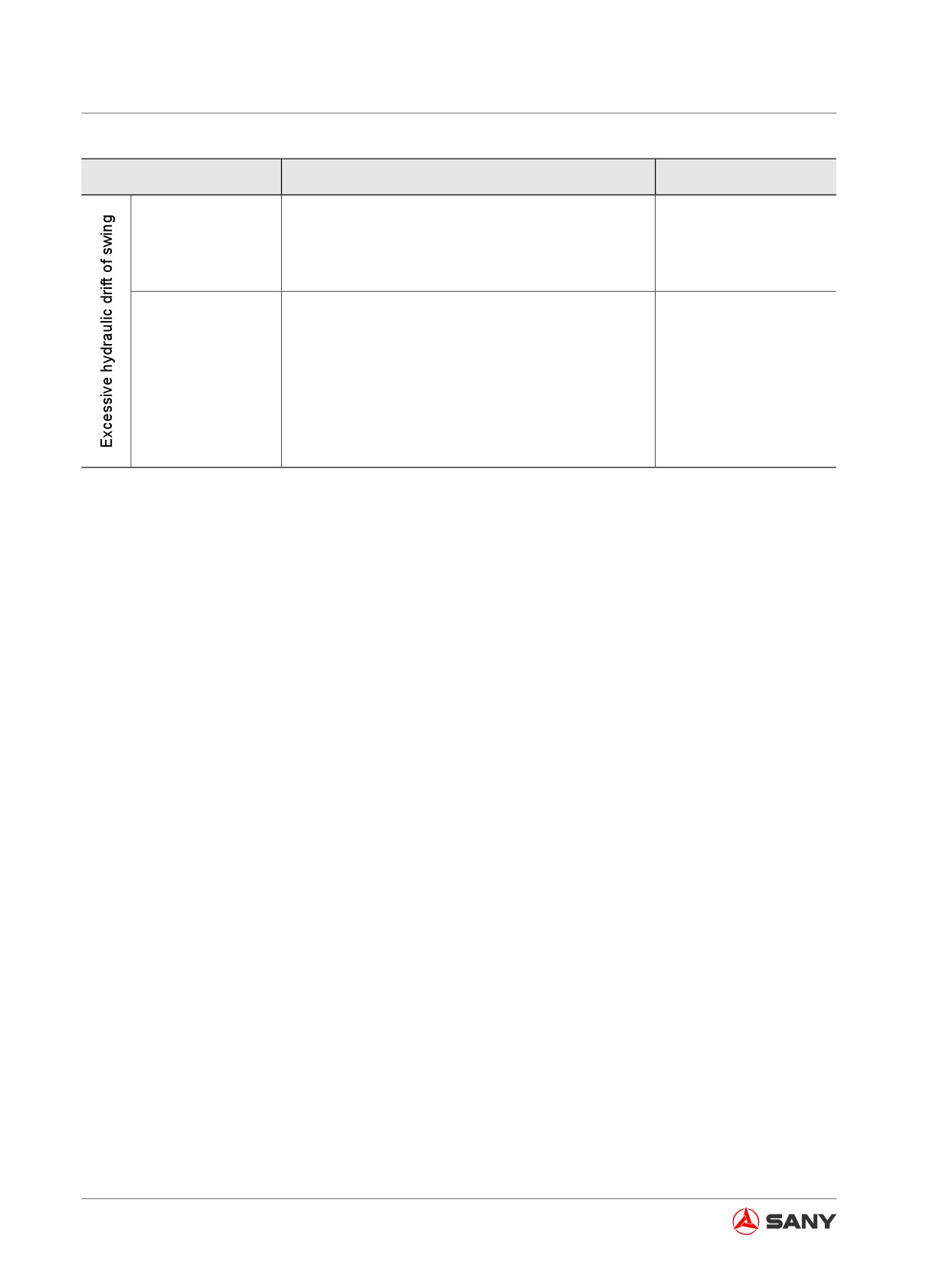
Troubleshooting
Failure
Causes
Remedy
When swing brake
● Swing brake control line failure
● Check/repair
engaged
● Swing motor (parking brake) failure
● Repair/replace
● Swing control valve (spool) failure
● Repair/replace
When swing brake
● Swing motor (relief valve) failure
● Repair/replace
disengaged
● Swing motor (feed valve) failure
● Repair/replace
Table 6-5
6-38
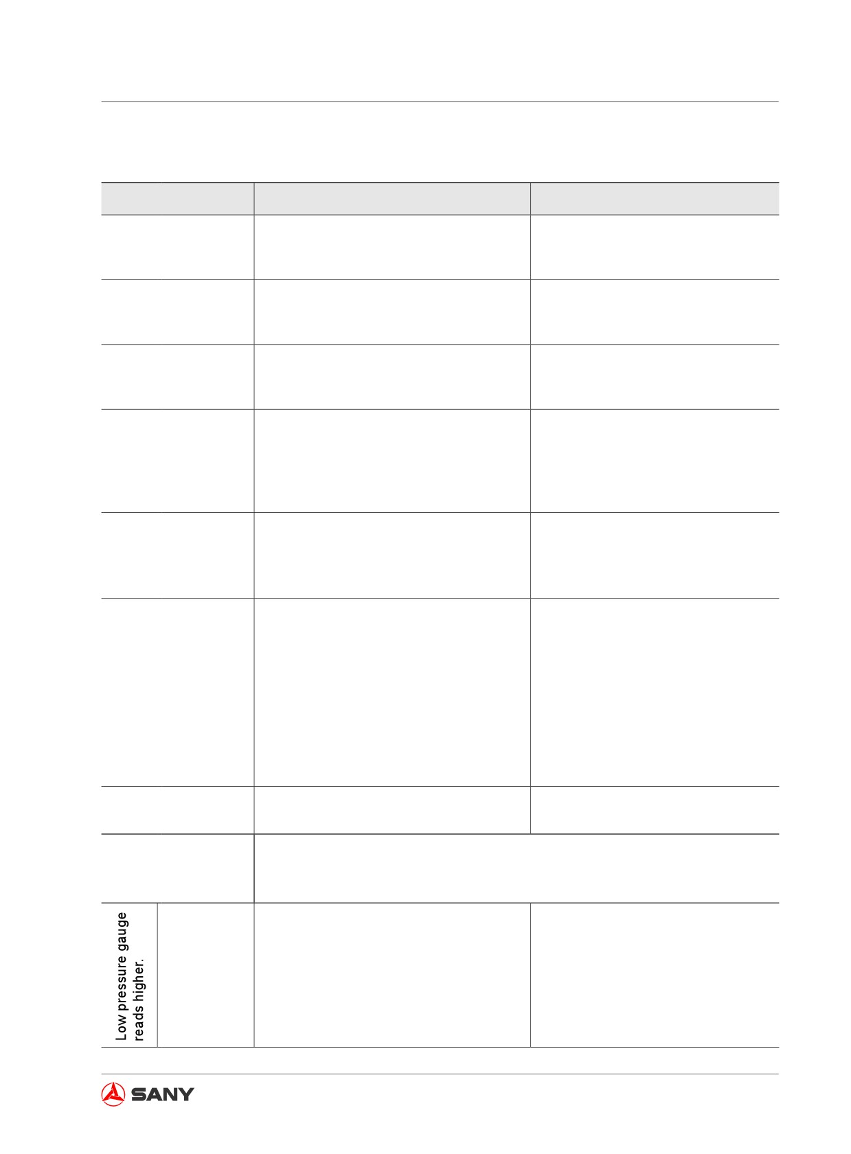
Troubleshooting
6.10 Other Common Failures
Failure
Causes
Remedy
● Loose fastener
● Check and retighten.
Structure member
● Bigger clearance between arm and buck-
● Reduce the clearance to a value that
noise loud
et end faces due to wear
is smaller than 1mm.
● Spring deformed and weak due to re-
Bucket tip falls off dur-
peated use of bucket tip pin
● Replace bucket tip pin
ing operation.
● Bucket tip pin not matching the adaptor
● Loose track
● Tighten the track
Track kinks.
● Traveling at high speed on rough road in
● Travel slowly on rough road in the
the direction of sprocket
direction of idler.
● Improper electrical connection or con-
nector contact
Fan not working
● Air flow control switch, relay or tempera-
● Repair/replace.
ture control switch damaged
● Fuse exploded or battery voltage low
● Air intake side blocked
Fan running but pro-
● Evaporator or condenser fin plugged,
● Clean/replace.
ducing less air flow
giving ineffective heat conduction
● Fan vane seized or damaged
● Compressor clutch not picking up due to
● Repair
wire break or defective contact of electri-
cal circuit
● Loose compressor belt
Compressor not work-
● Adjust the tension of compressor
ing or working with diffi-
belt
culty
●Wire break or failure of compressor
● Replace clutch coil
clutch coil
● Insufficient or excessive refrigerant
● Refill/drain the refrigerant to a suit-
able level
● Refrigerant leaks.
● Eliminate the leaking point.
Refrigerant insufficient
● Insufficient refilling
● Refill suitable amount of refrigerant.
Ambient temperature:30 ~ 50℃
High/low pressure
reading in normal op-
High pressure gauge: 1.47 ~ 1.67MPa(15 ~ 17kgf/cm2)
eration
Low pressure gauge:
0.13 ~ 0.20MPa(1.4 ~ 2.11kgf/cm2)
● Expansion valve opening excessively.
● Replace expansion valve.
Low pressure
● Defective contact of expansion valve
● Install thermo-bulb correctly.
tube surface
thermo-bulb
frosted
● Excessive refrigerant in the system
● Drain refrigerant to the specified
level.
6-39
Troubleshooting
Failure
Causes
Remedy
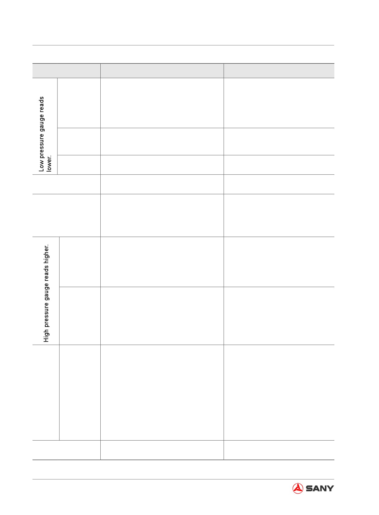
Both high and
low pressure
gauge read-
● Refill refrigerant to the specified
● Refrigerant insufficient
ings lower
level.
the standard
value.
Low pressure
● Low pressure hose blocked; expansion
● Repair the system. Replace reser-
gauge could
valve blocked by ice or contaminants.
voir in case of ice blockage.
read negative.
Evaporator
● Thermostat failure
● Replace thermostat.
frozen
Expansion valve inlet
● Expansion valve blocked.
● Clean/replace expansion valve.
felt cool and frosted.
Expansion valve outlet
is not felt cool. Low
● Expansion valve thermo-tube or bulb
● Replace expansion valve.
pressure could be
leaks.
negative.
Both high/
● Air trapped in circulation system.
low pressure
● Empty the system and vacuate to
gauges read
refill refrigerant.
higher than
● Excessive refrigerant refilled.
● Drain refrigerant to the specified
standard
level.
value.
Bad condens-
● Condenser blocked by dust and debris
● Clean the condenser.
ing effect of
● Condenser fan damaged
● Check/replace condenser fan.
condenser.
Both high and
low pressure
● Refrigerant insufficient
● Refill refrigerant as required.
gauges read
lower.
High
pressure
Low pres-
gauge
sure could be
● Low pressure line blocked/damaged
● Clean/replace faulty component.
reads
negative.
lower.
Condenser
and high
pressure tube
● Compressor internal failure
● Replace compressor.
hot
Bad refrigerating effect
● Hot water valve damaged and left open
● Replace hot water valve.
due active heater
Table 6-6
6-40
Specifications
Specifications
7 Specifications
7.1 Machine Dimensions
7-3
7.2 Working Ranges
7-4
7-1
Specifications
7 SPECIFICATIONS
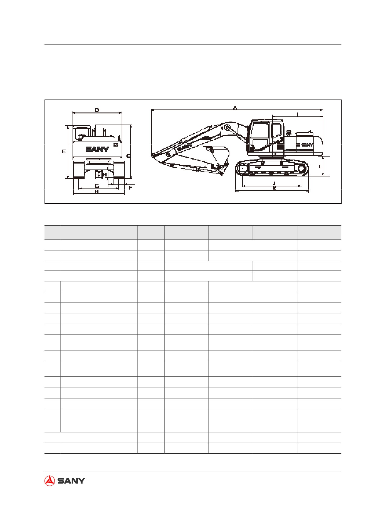
7.1 Machine Dimensions
Fig. 7-1
Item
Unit
SY115C9
SY135C8/C9
SY135C8(M)
SY155H
Operating weight
kg
12400
13,500
14,100
Bucket capacity
m3
0.48
0.54
0.6
Engine model
4BG1-TABGC-03-C2
4D34-TLE2A
BB-4BG1TRP
Engine power
kW/rpm
72.7 / 2200
70 / 2050
72.7 / 2200
A
Shipping length
mm
7280
7700
7700
B
Total width
mm
2550
2550
2550
C
Shipping height
mm
2810
2815
2815
D
Top width
mm
2480
2490
2580
E
Total height to top of cab
mm
2810
2740
2740
Standard width of track
F
mm
500
500
500
shoe
G
Gauge
mm
1990
1990
1990
Min. ground clearance
H
mm
422
425
425
(Excluding grouser )
I
Tail swing radius
mm
2325
2240
2240
J
Track grounding length
mm
2680
2930
2930
K
Track length
mm
3360
3665
3665
Ground clearance of upper
L
structure (excluding grous-
mm
915
870
870
er)
Travel speed (high/low)
km/h
3.5/5.5
3.5 / 5.5
3.5 / 5.5
Swing speed
rpm
12
12
12
Table 7-1
7-3
Specifications
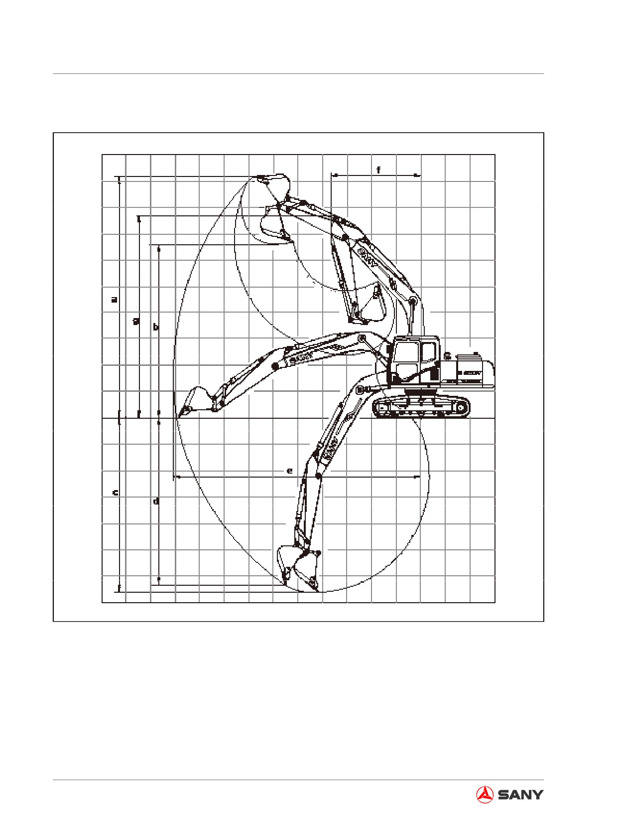
7.2 Working Ranges
Fig. 7-2
7-4
Specifications
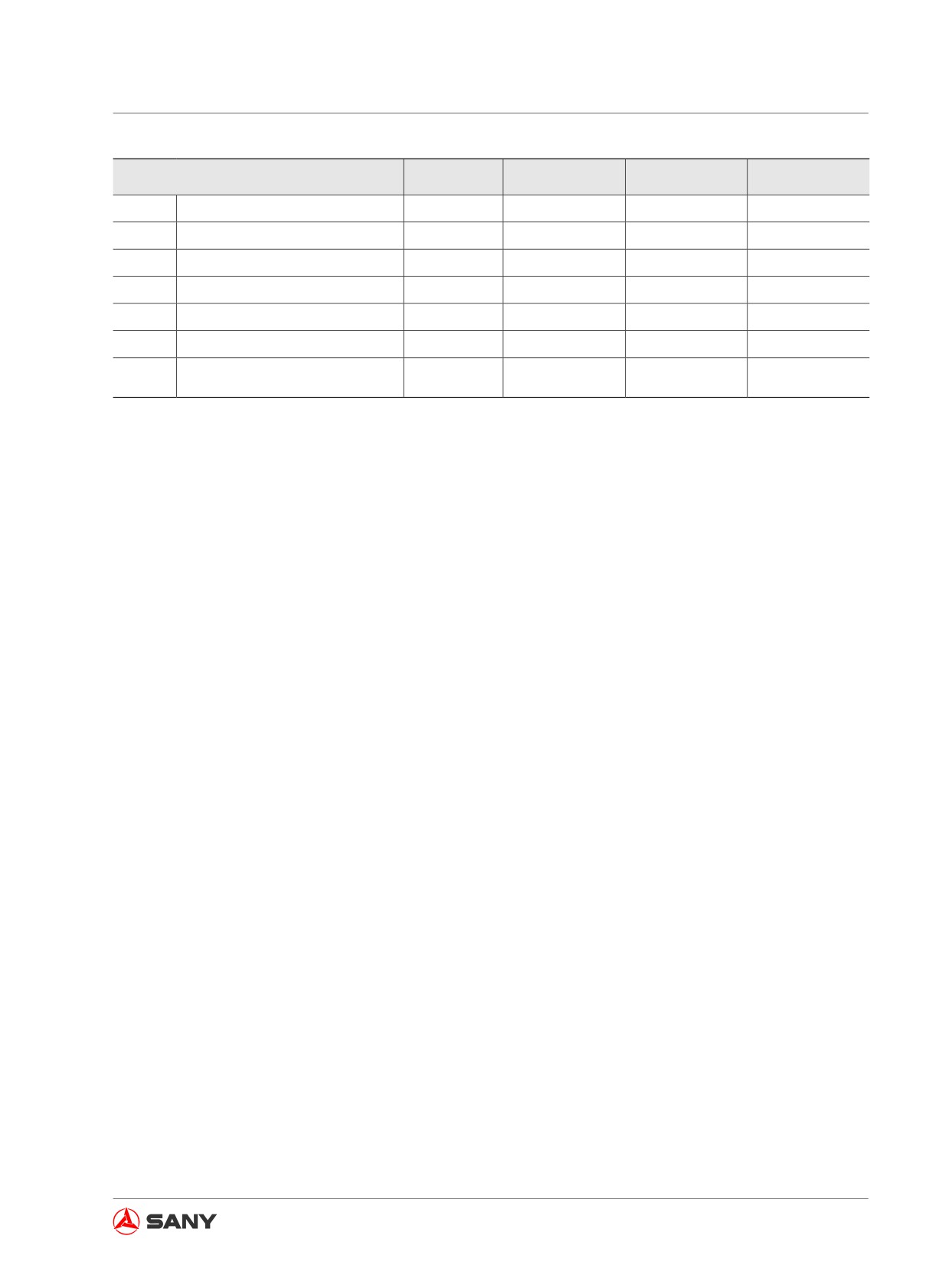
Item
Unit
SY115C9
SY135C8/C9
SY155H
a
Max cutting height
mm
7780
8645
8625
b
Max dumping height
mm
5530
6175
6120
c
Max digging depth
mm
5165
5500
5520
d
Max vertical digging depth
mm
4925
4890
5005
e
Max horizontal reach
mm
7605
8290
8330
f
Min. swing radius
mm
2600
2500
2315
Maximum height at minimum
g
mm
5995
6500
6495
swing radius
Table 7-2
7-5
Optional Equipment
Optional Equipment
8 Optional Equipment
8.1
General Safety
8-3
8.1.1 Selection precautions
8-3
8.1.2 Reading the instruction books
8-3
8.1.3 Removal and installation precautions
8-3
8.1.4 Operation precautions
8-4
8.2
Hydraulic Control Elements and Oil Circuit
8-6
8.2.1 Location of the components
8-6
8.2.1.1 Stop valve
8-6
8.2.1.2 Selector valve
8-7
8.2.1.3 Control pedal
8-7
8.2.2 Hydraulic circuit
8-8
8.2.2.1 Hydraulic circuit switching
8-8
8.2.2.2 Shifting to breaker / general optional equipment
8-8
8.2.2.3 Connecting hydraulic oil circuit
8-9
8.2.2.4 Hydraulic oil passage
8-10
8.2.3 Optional equipment removal and installation
8-11
8.2.3.1 Removal
8-11
8.2.3.2 Optional equipment installation
8-13
8.2.4 Hydraulic oil and hydraulic tank filter - change/replace
8-15
8.2.5 Long-term storage
8-16
8.2.6 Hydraulic specifications
8-16
8.3
Optional equipment Guide
8-17
8.3.1 Work equipment combination
8-17
8.3.2 Bucket tips selection
8-19
8.3.2.1 Rockwork bucket tips
8-19
8-1
Optional Equipment
8.3.2.2 Earthwork bucket tips
8-19
8.4
Recommended Operations
8-20
8.4.1 Hydraulic breaker
8-20
8.4.2 Hydraulic breaker operation
8-21
8.5
Restricted Operations
8-22
8.6
Hydraulic Breaker Lubrication
8-25
8.7
Quick Coupler and Control System
8-26
8.7.1 Quick coupler installation
8-26
8.7.2 Operating precautions
8-28
8.8
Refueling System
8-29
8.8.1 Introduction
8-29
8.8.2 Components
8-30
8.9
Central Lubrication System
8-31
8.9.1 Scheme and components
8-31
8.9.2 System working principle
8-33
8.9.3 Setting the lubrication time of electric grease pump
8-34
8.9.4 Technical description
8-35
8.9.5 Adding grease with electric pump
8-36
8-2
Optional Equipment
8 OPTIONAL EQUIPMENT
8.1 General Safety
It is important to be safe when an optional
equipment is used. Read the following precau-
tions before selecting, installing and operating
an optional equipment.
8.1.1 Selection precautions
● Consult your Sany distributor before install-
ing an optional equipment to your machine.
Front guard, top guard or other protective
structures may be required according to
the type of optional equipment to be used.
● Only Sany-approved optional equipment
can be installed. Sany assumes no re-
sponsibility to accidents, losses or failures
caused by any attachment that has not
been approved by Sany.
8.1.2 Reading the instruction books
● Read and understand the instruction books
of your machine and of attachment or op-
tional equipment before installation and
operation.
● If the instruction book is missing or dam-
aged, ask the manufacturer or your Sany
distributor to obtain a new one.
8.1.3 Removal and installation precau-
tions
To be safe, the following items must be ob-
served before you remove or install an attach-
ment or optional equipment.
● The removal or installation procedure must
be performed on a hard, level ground.
8-3
Optional Equipment
●
If the job has to be done by two or more
persons, appoint a chief and follow his in-
struction.
●
Use a crane if you handle an object that
weighs over 25 kg. (Only eligible, experi-
enced personnel with official license are
allowed to operate a crane.)
●
Never stay under an object that is being
lifted by a crane.
●
Do not operate your machine when an
object is being lifted with crane during re-
moval or installation. Support can be used
to prevent falling from the object when nec-
essary.
●
When a heavy part is to be removed, it is
necessary to consider the impact to ma-
chine balance after removal. To prevent the
machine from tipping over, support your
machine, if necessary, before removing the
heavy component.
●
Before or after the optional equipment has
been installed or removed, make sure that
it is stable without the danger to tip.
●
For more information about removal and
installation please consult Sany distributor.
8.1.4 Operation precautions
Keep the following procedures in mind when
installing a larger or heavy optional equipment.
Before the operation, move your machine to a
safe ground for trial operation. Make sure that
you know very well the movement, center of
gravity, and working range of your machine.
● If the machine stays inclined, swinging op-
eration is not allowed in order to prevent
tipping of the machine.
● Keep a safe distance to surrounding barri-
ers during operation.
● Pay attention to the following points when
installing a heavy optional equipment.
8-4
Optional Equipment
★ Heavy optional equipment probably re-
quires a larger space for swinging op-
eration. There might be the danger of
impacting other objects if the swinging
range has not been calculated accu-
rately. A larger space must be prepared
before performing the swinging opera-
tion.
★When the lifting of heavy optional
equipment is held, the distance mov-
ing downward is relatively longer due
to gravity. In this case, it should be
lowered to the ground instead of being
held in air.
★ Never swing, lower or stop your ma-
chine suddenly in order to prevent it
from tipping over.
★ Never extend or retract the boom cylin-
der suddenly in order to prevent impact
that may cause the machine to tip.
8-5
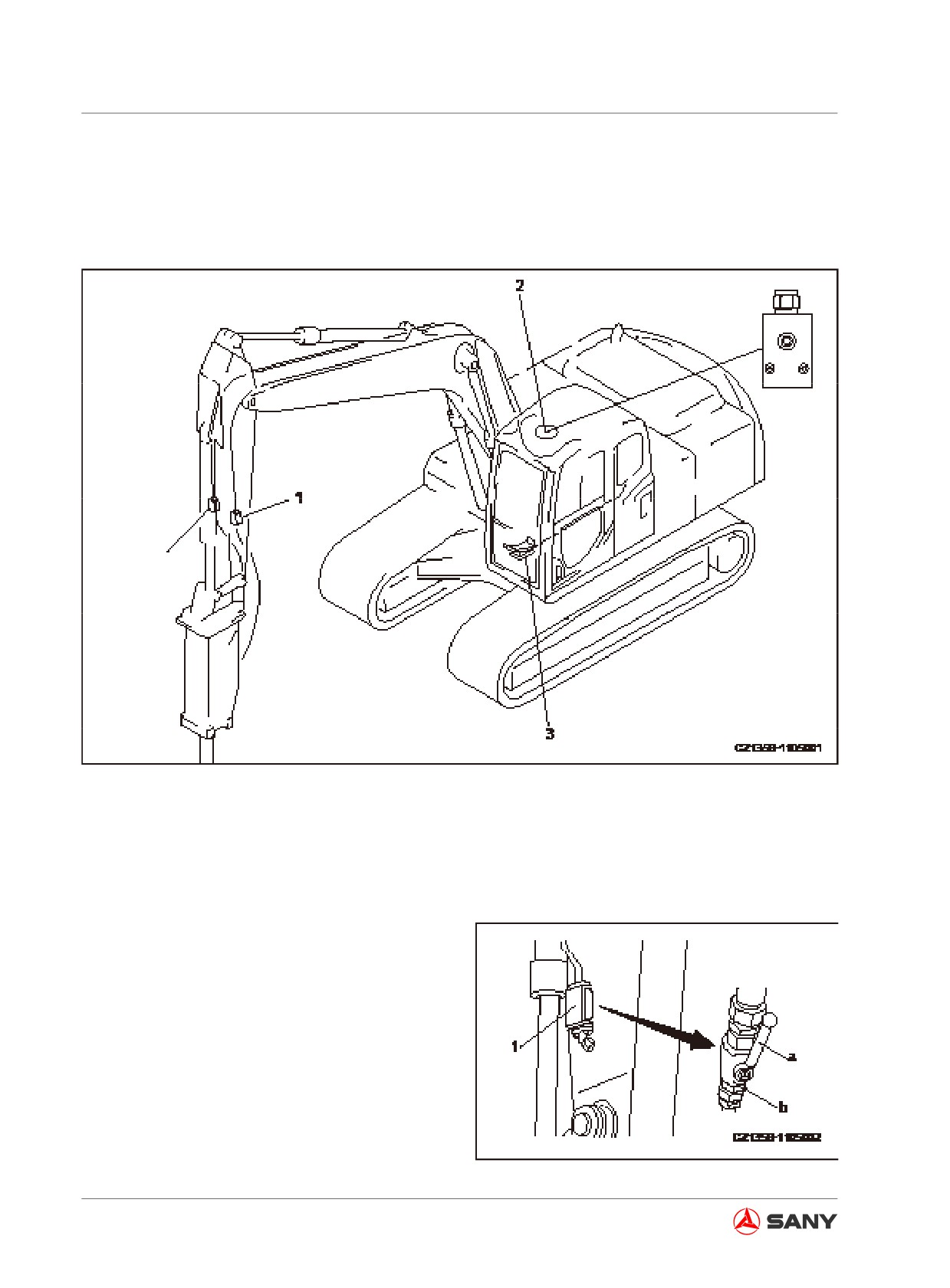
Optional Equipment
8.2 Hydraulic Control Elements and Oil Circuit
8.2.1 Location of the components
Fig. 8-1
(1) Stop valve
(2) Selector valve
(3) Control pedal
8.2.1.1 Stop valve
Stop valve stops hydraulic oil flow.
(a) Unlocked position allows flow of the hy-
draulic oil.
(b) Locked position stops flow of the hydraulic
oil.
Switch the valve to locked position when re-
moving or installing an optional equipment.
Fig. 8-2
8-6
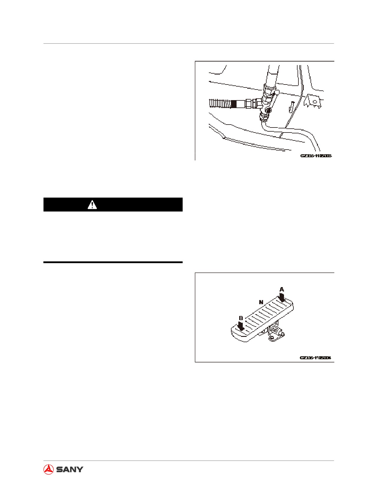
Optional Equipment
8.2.1.2 Selector valve
Selector valve changes flowing direction of hy-
draulic oil.
The change of direction is made according to
the working mode selected. The working mode
must be applicable to the installed optional
equipment. For changing the working mode,
see“Hydraulic circuit” on page 8-8.
Fig. 8-3
8.2.1.3 Control pedal
WARNING
Do not operate when placing your foot on
the pedal. If the pedal is pushed mistaken-
ly, the optional equipment will move sud-
denly and cause severe accidents.
Control pedal is used to control the optional
equipment.
When the front, center, or rear of the pedal is
pushed down, the optional equipment will op-
erate as the following.
Hydraulic breaker
Front (A): Operate
Center (N): Stop
Fig. 8-4
Rear (B): Stop
For other optional equipment, consult its man-
ufacturer for installation in order to confirm the
operation of pedal and optional equipment be-
fore operating your machine.
8-7
Optional Equipment
8.2.2 Hydraulic circuit
Note:
● When the breaker is mounted, the oil return line must be connected directly to the return filter.
Therefore, do not use the return line except for mode B.
● In the stand-by valve, the safety valve's standard pressure was set at the factory before the
machine was delivered. When mode B is selected, the pressure is set to 20.6MPa (210kgf/
cm2, 2980PSI); when the mode of hydraulic shear is chosen, the pressure is set to 27.4MPa
(280 kgf/cm2, 3980PSI). Readjustment may be necessary according to the type of optional
equipment. In this case, please contact Sany distributor for adjustment.
8.2.2.1 Hydraulic circuit switching
● Set the working mode on the monitor according to the following standards according to the
type of optional equipment.
● The pressures set for the safety valve in the stand-by valve and for the switch of hydraulic line
are determined by the working mode selected.
Optional equipment
Mode
Hydraulic line
Safety Valve Pressure Setting
Hydraulic path forms
automatically at the
When delivered from factory:
One-way hydraulic optional
B
control valve where the
equipment, such as breaker
return oil does not pass
20.6Mpa (210kgf/ cm2 2980PSI)
through.
Hydraulic path forms
Dual-action hydraulic optional
automatically at the
When delivered from factory:
equipment, such as hydraulic
S
control valve where
shear
the return oil passes
27.4MPa (280kgf/cm2, 3980PSI)
through.
8.2.2.2 Shifting to breaker / general optional equipment
● When installing an optional equipment with working mode B
(a) Breaker hydraulic path (one-way hydraulic path) has been formed.
(b) The overflow valve is set to low pressure.
When delivered from the factory: 20.6MPa (210kgf/cm2, 2980PSI)
● When installing an optional equipment with working mode S
8-8