SANY Crawler Hydraulic Excavator SY115C9/135C/155H. Operation and Maintenance Manual - page 11
Optional Equipment
(a) Shear hydraulic path (dual-action hy-
draulic path) has been formed.
(b) The overflow valve is set to high pres-
sure.
When delivered from the factory:
27.4MPa 280kgf/cm2, 3980PSI
8.2.2.3 Connecting hydraulic oil circuit
Connect the hydraulic lines to the optional
equipment according to the following steps.
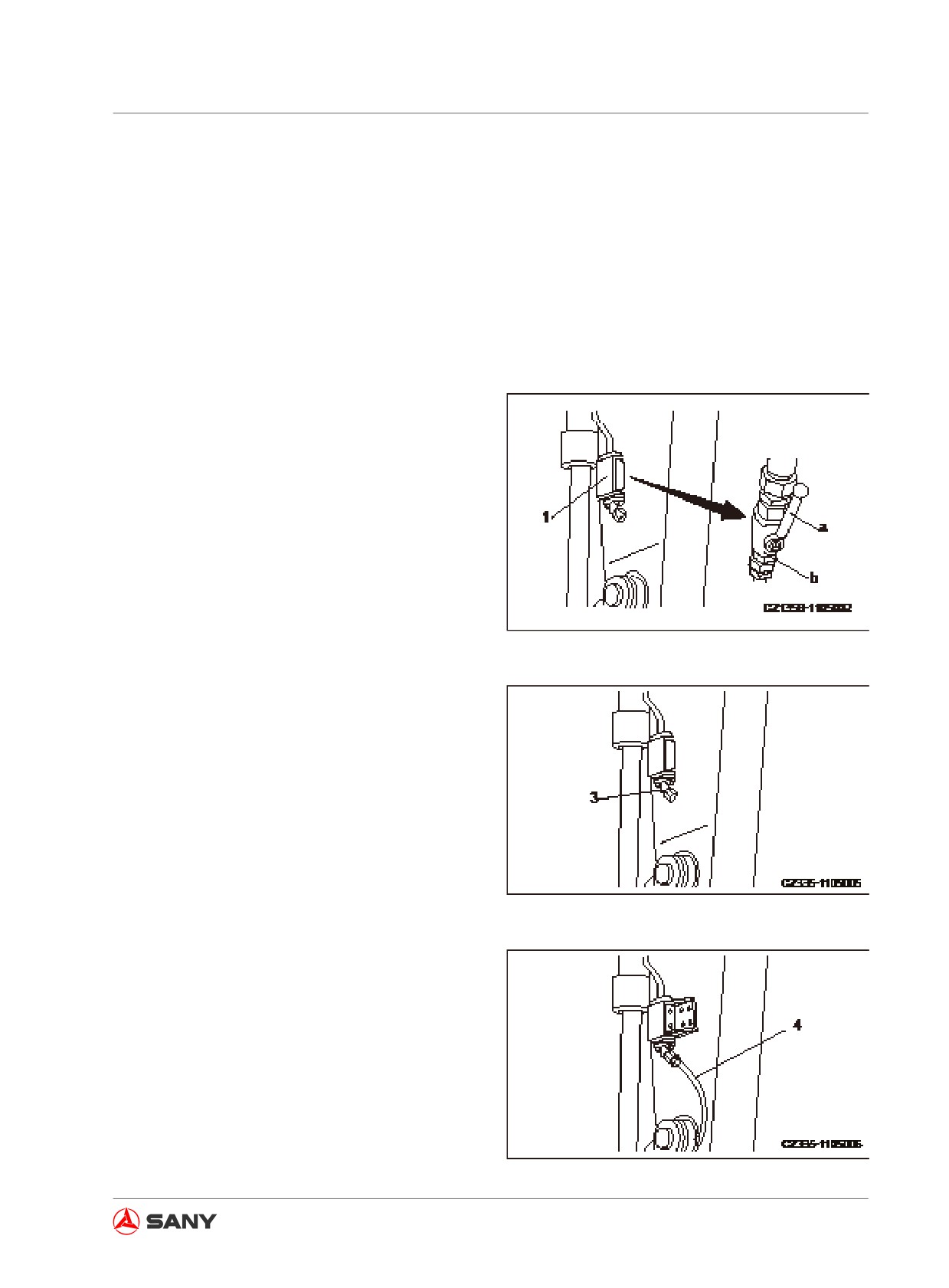
1. Check the stop valve, which should be in
the locked position (b).
(a) unlocked: allows flow of the hydrau-
lic oil (the arrow-indicated direction is
parallel to the longitudinal direction of
arm).
Fig.
8-5
(b) locked: stops flow of the hydraulic oil
(the arrow-indicated direction is per-
pendicular to the longitudinal direction
of arm).
2. Remove the screw plug (3) from the end of
the stop valve line.
Note:
The disassembled parts should not be lost or
Fig.
8-6
damaged.
3. The optional equipment manufacturer is
responsible to connect the line (4) of the
optional equipment after the screw plug (3)
has been removed.
Connection sizes and additional accumula-
tor may vary according to different optional
equipment manufacturers. Please consult
Sany distributor in this regard.
Fig.
8-7
8-9
Optional Equipment
8.2.2.4 Hydraulic oil passage
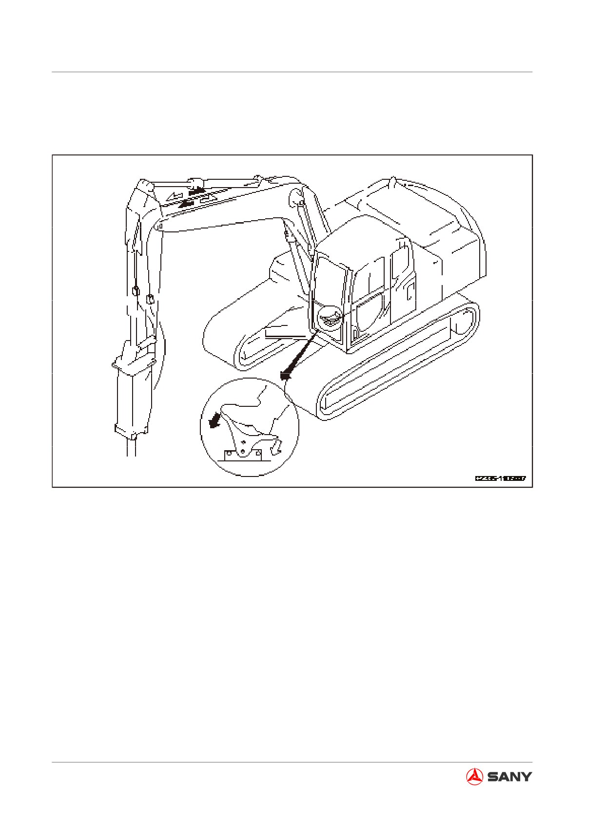
The operating directions of the pedal and hydraulic path are shown below.
Fig. 8-8
By pushing the front of the pedal, the hydraulic oil flows to the left of the work equipment; by
pushing the rear, the hydraulic oil flows to the right. (Only the front part of the pedal can be oper-
ated upon the installation of breaker.)
8-10
Optional Equipment
8.2.3 Optional equipment removal and installation
8.2.3.1 Removal
1. Lower the work equipment to the ground
and shut down the engine.
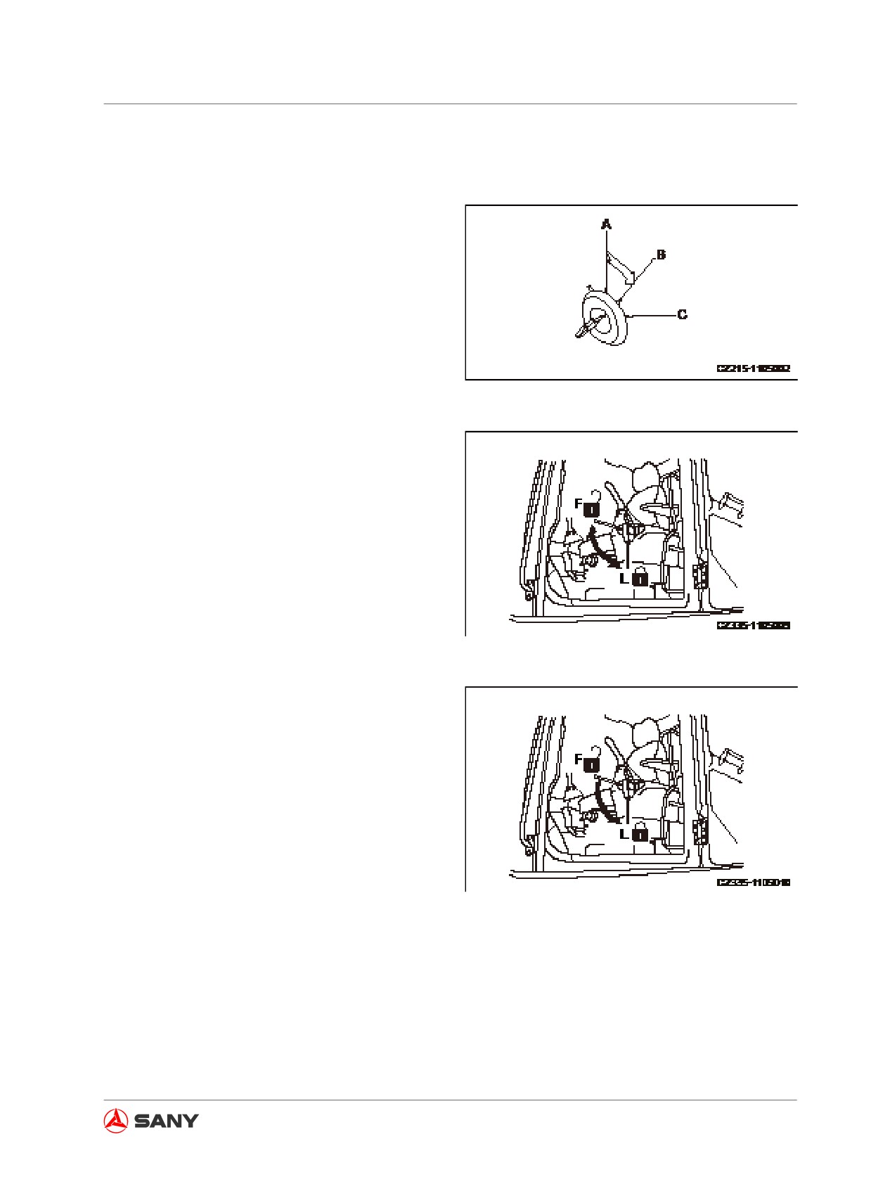
2. Turn the start switch to ON position (B),
and place the lockout control to FREE
position (F).
Fig. 8-9
3. After finishing step 2, fully cycle each
control level and control pedal for 2-3 times
within 15 seconds in order to release the
internal pressure remained in the hydraulic
lines.
Fig. 8-10
4. Place the lockout control to LOCK position
(L).
Fig. 8-11
8-11
Optional Equipment
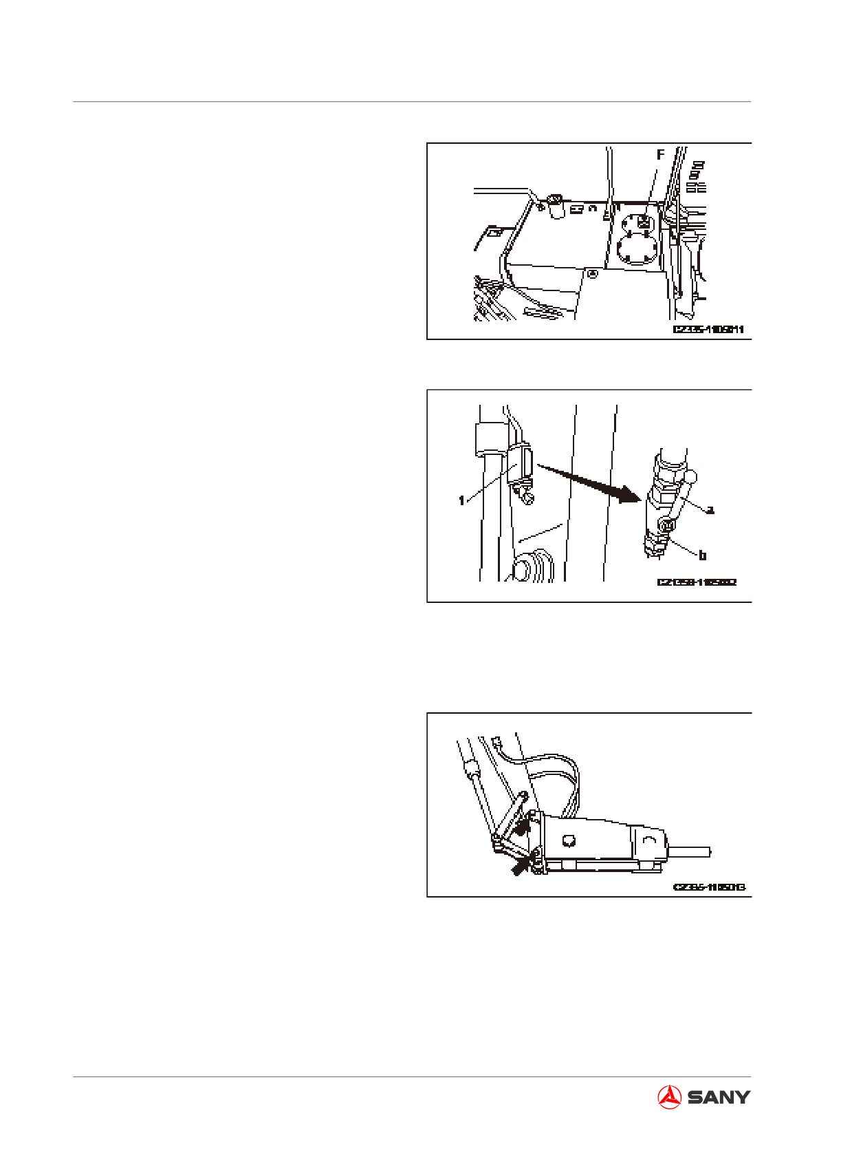
5. The breather valve (F) on top of the
hydraulic tank can be used to release the
internal pressure of the hydraulic lines.
To release the pressure completely, turn
and open the butterfly nut on the breather
valve (F) and press the relief button to re-
lease the pressure.
Fig. 8-12
6.
Check the temperature of hydraulic oil,
which should be cooled to a safe tempera-
ture, and then turn the rotor of the stop
valve (mounted to the inlet and outlet lines
to the side of the arm) to locked position (b).
(a) unlocked: allows flow of the hydraulic
oil
(the arrow-indicated direction is
parallel to the longitudinal direction of
arm).
(b) locked: stops flow of the hydraulic oil
Fig. 8-13
(the arrow-indicated direction is per-
pendicular to the longitudinal direction
of arm).
7.
Disconnect the hose at the side of the
optional equipment. Install the screw plugs
to the two outlets.
The screw plugs are used to prevent that
the invasion of foreign materials could lead
to the malfunction of the optional equip-
ment. Put the optional equipment in stor-
age after the screw plugs have been in-
stalled properly.
Fig. 8-14
8.
Remove the two installation pins, disas-
semble the optional equipment, and install
the bucket.
For more information on the bucket instal-
lation procedures see“Bucket Replace-
ment” on page 5-47.
8-12
Optional Equipment
9. Check the oil level in the hydraulic tank af-
ter the bucket has been installed properly.
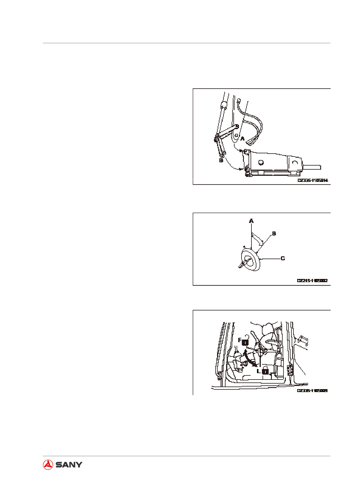
8.2.3.2 Optional equipment installation
1. Remove the bucket.
2. Place the optional equipment to a flat
surface. Install the optional equipment to
the arm with the pin (A) followed by the pin
(B).
Fig. 8-15
3. Lower the equipment to the ground and
shut down the engine.
4. Turn the start switch to ON position (B),
and place the lockout control to FREE
position (F).
5. After finishing step 2, fully cycle each
control level and optional equipment con-
trol pedal for 2-3 times within 15 seconds
Fig. 8-16
in order to release the internal pressure
remained in the hydraulic lines.
Fig. 8-17
8-13
Optional Equipment
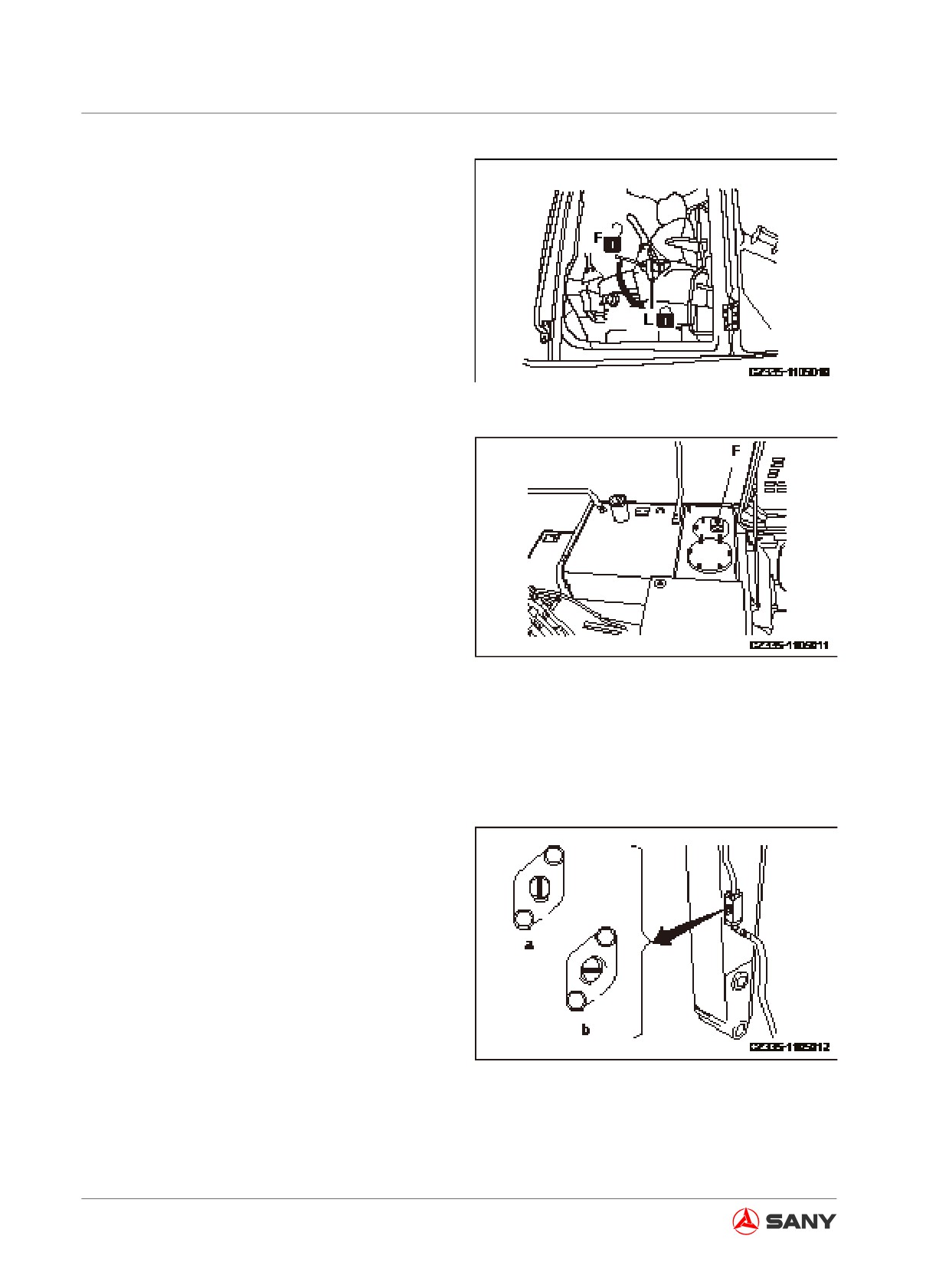
6.
Place the lockout control to LOCK position
(L).
7.
The breather valve (F) on top of the
hydraulic tank can be used to release the
internal pressure of the hydraulic lines.
To release the pressure completely, turn
and open the butterfly nut on the breather
valve (F) and press the relief button to re-
lease the pressure.
Fig.
8-18
8.
Check the temperature of the hydraulic
oil, which should be cooled down to a safe
temperature. Remove the two screw plugs
from the inlet and outlet. Be careful not to
contaminate the hose connections with any
dirt or soil.
If the O-ring is broken, replace it with a
new one.
9.
Connect the hose to the side of the op-
Fig.
8-19
tional equipment.
When connecting the hose, check the oil
flow direction and be careful not to make
any mistakes.
10. Turn the rotor of the stop valve (mounted
to the inlet and outlet lines to the side of
the arm) to FREE position (a).
(a) unlocked: allows flow of the hydraulic oil
(the arrow-indicated direction is parallel
to the longitudinal direction of arm).
(b) locked: stops flow of the hydraulic oil (the
arrow-indicated direction is perpendicu-
lar to the longitudinal direction of arm).
Fig.
8-20
11. Check the oil level in hydraulic tank after
installation of the optional equipment.
8-14
Optional Equipment
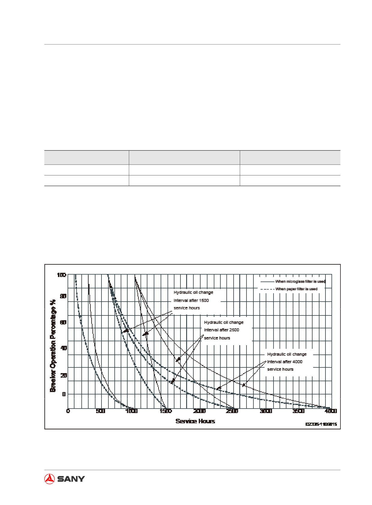
8.2.4 Hydraulic oil and hydraulic tank filter - change/replace
The operation of hydraulic breaker could contaminate the hydraulic system and deteriorate the
hydraulic oil. In this case, the hydraulic oil and hydraulic tank filter should be changed more of-
ten, as compared with the machine installed with bucket. Otherwise, damage could occur in the
hydraulic breaker, hydraulic pump and other hydraulic components. The recommended replace-
ment intervals are shown below. (For information about how to change oil and replace a filter, see
related items in the Maintenance Section.)
Table 8-1 Change interval (hours)
Machine with Hydraulic Breaker
Machine with Common Bucket
Hydraulic oil
600
1500 or 2500 or 4000
Filter cartridge
100
1000
Note:
The figures in the above table are determined at 100 percent operation with hydraulic breaker. As
the operating hours of hydraulic breaker reduce, the change intervals could be prolonged corre-
spondingly as shown in the following illustration.
The filter cartridge must be replaced after the breaker has been operated for 100 hours.
Fig. 8-21
8-15
Optional Equipment
8.2.5 Long-term storage
The following procedures shall be followed
when the equipment is to be stored for a long
period of time.
● Turn the stop valve to locked position.
● Screw the plug on the valve.
● Place the latch pin to locked position.
Operating the pedal without installing the
breaker or general optional equipment may
cause overheating or other problems.
8.2.6 Hydraulic specifications
● Max. combined flow 2×63 L/min
● The overflow pressure of the safety valve
in the stand-by valve has been set to
27.4MPa (280 kgf/cm2, 3980PSI) (except
mode B).
● The pressure to activate the safety valve
in the stand-by valve has been set to
24.5MPa (250 kgf/cm2, 3550PSI) (except
mode B).
● The overflow pressure of the safety valve
in the stand-by valve has been set to 15-
17MPa (153-174 kgf/cm2, 2178-2469 PSI)
(mode B).
● The pressure to activate the safety valve
in the stand-by valve has been set to
15.2MPa (155kgf/cm2, 2200PSI) (mode B).
Besides the valves listed above, we also of-
fer valves in which the overflow pressure of
safety valve can be set to 24.5MPa (250kgf/
cm2, 3550PSI) and its activating pressure can
be set to 20.1MPa (205 kgf/cm2, 2911PSI).
Please consult Sany dealer in your locality.
8-16
Optional Equipment
8.3 Optional equipment Guide
WARNING
Read the optional equipment instruction
manual and related sections about option-
al equipment.
● Safety issue will be involved when in-
stalling any optional equipment. There-
fore, please consult Sany distributor
before the installation.
● Installing an optional equipment with-
out approval from Sany distributor
could lead to safety problems which
may impair the operation and service
life of your machine.
● Sany assumes no responsibility for
any injuries, accidents or damage re-
sulted from the installation of unauthor-
ized optional equipment.
8.3.1 Work equipment combination
WARNING
● There is the danger of impacting the
cab or machine body due to the type or
combination of work equipment.
● Operating a work equipment for the
first time requires to check for the dan-
ger of any intervention before starting.
Operate your machine carefully.
8-17

Optional Equipment
Note:
● In excavation, the boom may intervene with the undercarriage when the boom is fully low-
ered. Be careful with the operation of the boom.
● For excavating or loading hard soil or soft soil containing gravels, reinforced rock-digging
bucket with higher strength and abrasion resistance is recommended.
● It is recommended using high-strength and high-antiwearing rockwork bucket when you dig or
load hard soil or soft soil containing stone pieces.
Capacity
Outer Width
Weight
Stand Arm(◇)
Bucket Type
m3
mm
Kg
m
Remark
(cu.yd)
(ft in)
(lb)
(ft in)
Rockwork
0.48
882
405
2.36
Standard
(SY115C9)
(0.64)
(2ft 10in)
(893)
(7 ft 9 in)
Rockwork
0.53
880
480
2.5
Standard
Earthwork
(0.71)
(2ft 10in)
(1058)
(8 ft 2 in)
(SY135C8)
0.53
946
478
2.5
Rockwork
(0.71)
(3 ft 1 in)
(1052)
(8 ft 2 in)
0.54
860
484
2.5
Standard
Earthwork
(0.71)
(2ft 10in)
(1058)
(8 ft 2 in)
(SY135C9)
0.6
950
960
2.5
Optional
(0.71)
(3 ft 1 in)
(1052)
(8 ft 2 in)
0.53
946
479.6
2.5
Rockwork
Earthwork
(0.71)
(3 ft 1in)
(1057)
(8 ft 2 in)
(SY155H)
0.6
986
489
2.5
Standard
(0.80)
(3 ft 3 in)
(1078)
(8 ft 2 in)
Table 8-2
◇―Digging or loading materials of specific gravity ≤ 1.8 t/m3
8-18
Optional Equipment
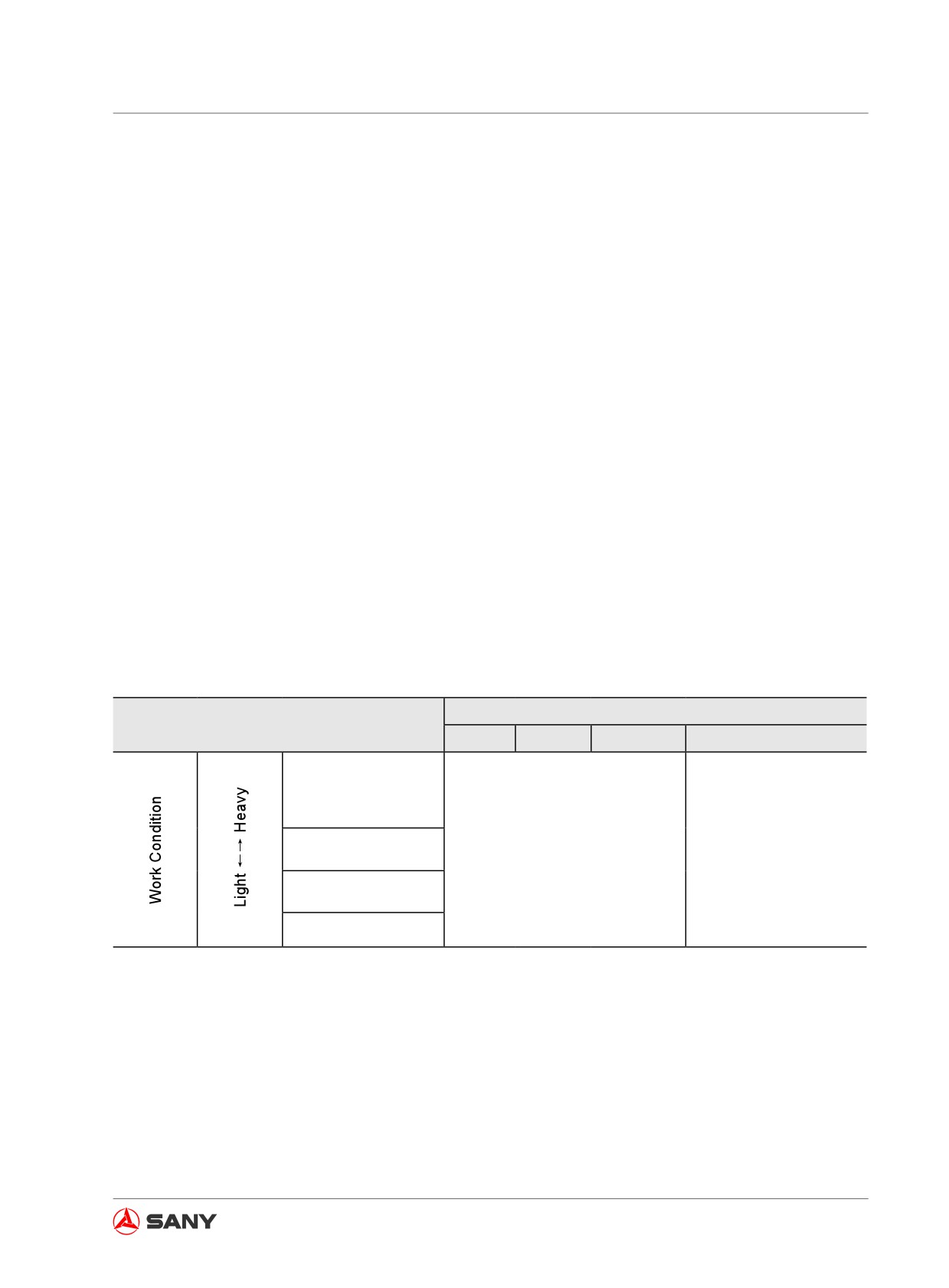
8.3.2 Bucket tips selection
Bucket tips may break off the adapter due to the working condition. In this case, suitable bucket
tips must be determined. Currently, we offer bucket tips with a lateral pin. So the following types
of bucket tips are recommended according to different working conditions.
8.3.2.1 Rockwork bucket tips
● Would be used at where the bucket tips service life could be impaired, such as loading hard
rocks.
● Would be used at where the bucket tips will not penetrate into the soils, such as handling
gravels after blasting or loosening the soils.
● Would be used at where heavy load operation is carried out, such as tapping or pulling the
rock with bucket tips.
8.3.2.2 Earthwork bucket tips
● Would be used at where the bucket tips will penetrate into the soils, such as excavating and
loading sand or clay.
Applicable Worksite
Rocks
Gravel
Sandstone
Clay and loose sand
Excavation during
pile-driving
Scraping the earth
Rockwork Tips
Earthwork Tips
General Excavation
Loading
Table 8-3
8-19
Optional Equipment
8.4 Recommended Operations
The following instruction must be followed
when operating an excavator with optional
equipment.
Note:
Select the optimum model of optional equip-
ment for your hydraulic excavator.
● The type of optional equipment to be in-
stalled and the model of special optional
equipment may vary according to the mod-
el of your hydraulic cylinder. In this case,
for selecting the optimum optional equip-
ment, please consult Sany distributor.
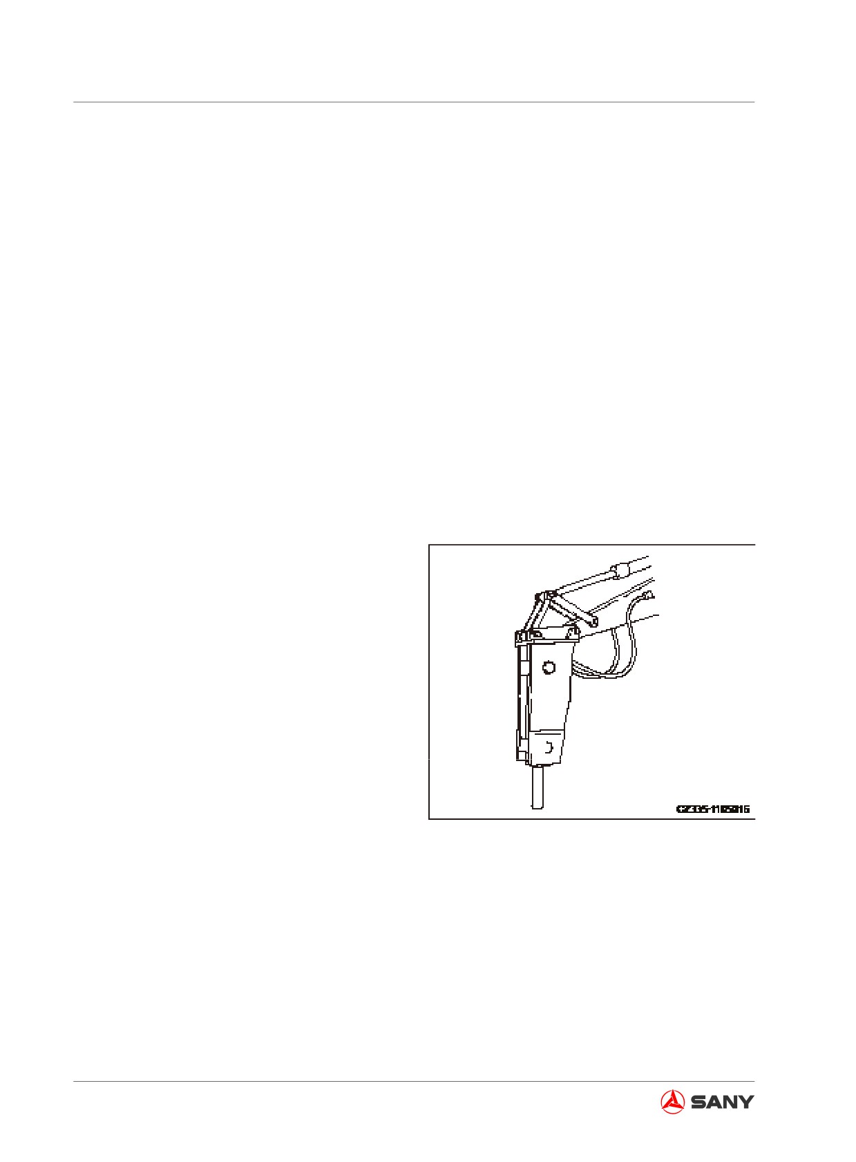
8.4.1 Hydraulic breaker
Major applications:
● Crushing rocks
● Demolition
● Road Engineering
This optional equipment can be used widely
for, such as demolishing buildings, breaking
road surface or slag, tunneling, crushing rocks,
and breaking operation at quarry.
Fig. 8-22
8-20
Optional Equipment
8.4.2 Hydraulic breaker operation
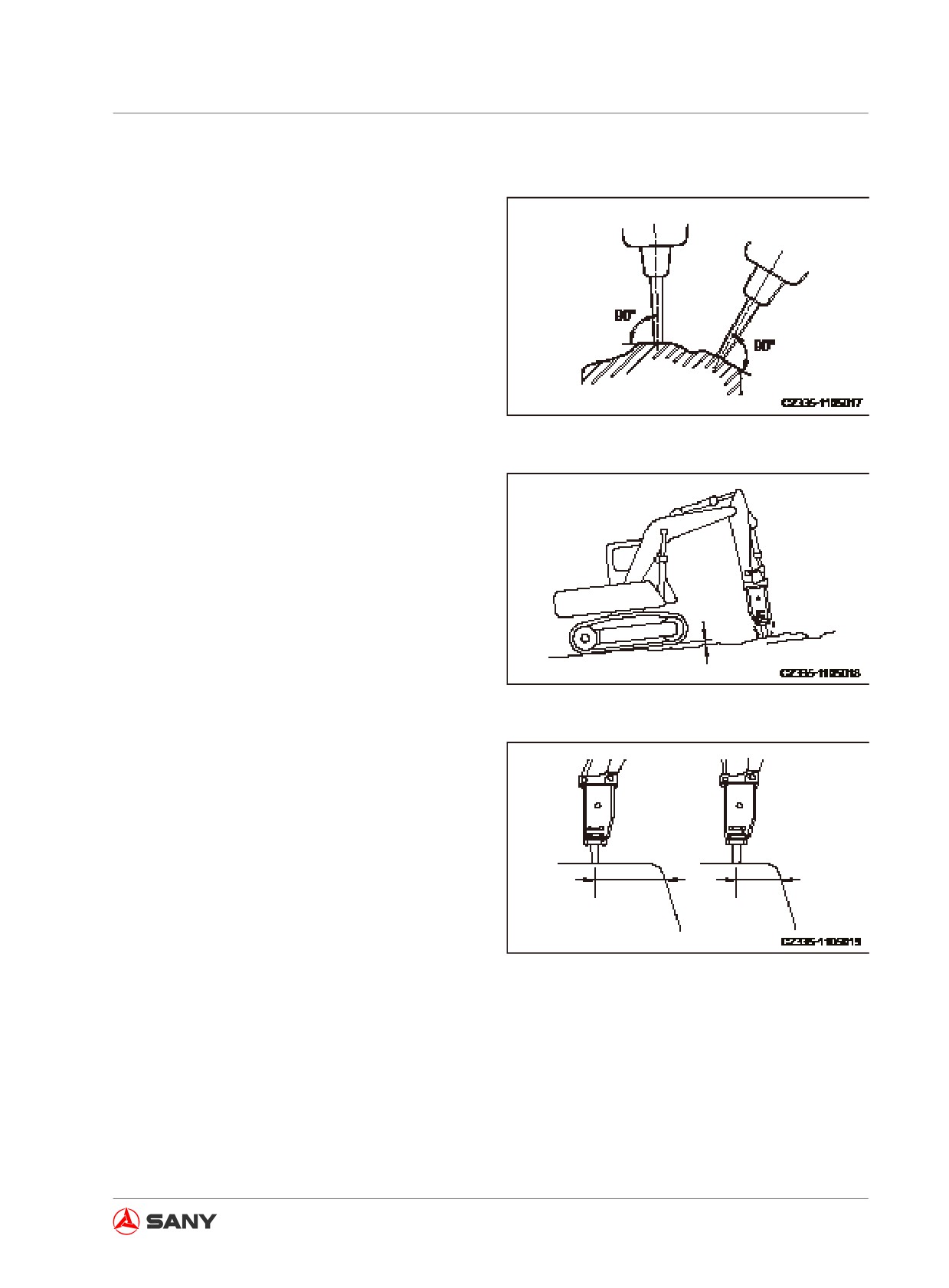
1. Press the breaker chisel vertically and
firmly onto the object to be broken during
breaking operation.
2. Press the breaker chisel tightly onto the
working surface when striking and slightly
raise the front of the undercarriage about 5
mm (0.2 in) from the ground, as shown in
the right illustration. This clearance above
ground shall not exceed 5 mm (0.2 in).
Fig. 8-23
Note:
The excavator shall not be raised too much.
Fig. 8-24
3. If the same surface cannot be penetrated
or broken by the chisel within one minute
under continuous striking, change the
struck position and try to break it near the
edge.
Fig. 8-25
8-21
Optional Equipment
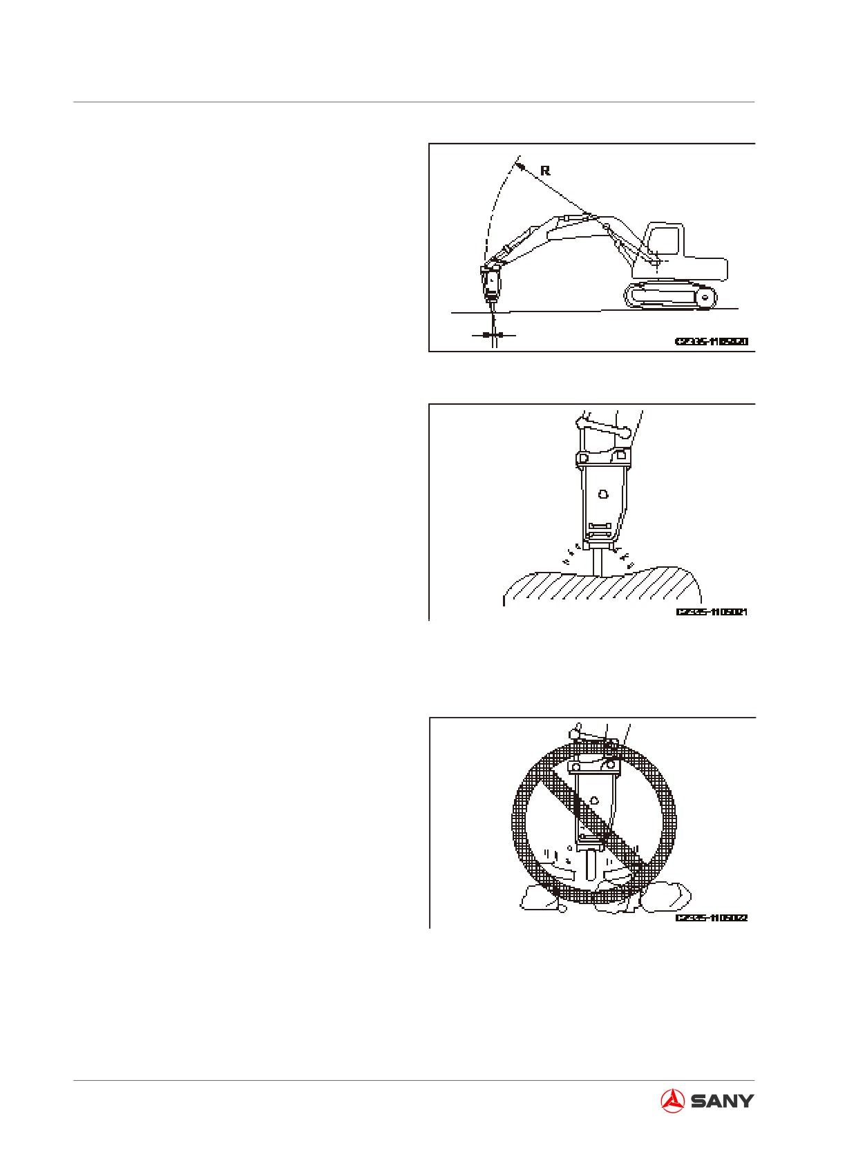
4. The chisel's penetrating direction will devi-
ate gradually to the working direction of
breaking hammer. It is important to align
them by readjusting the bucket cylinder.
Fig. 8-26
5. Always press the chisel properly on the
working surface in order to prevent striking
without resistance.
Fig. 8-27
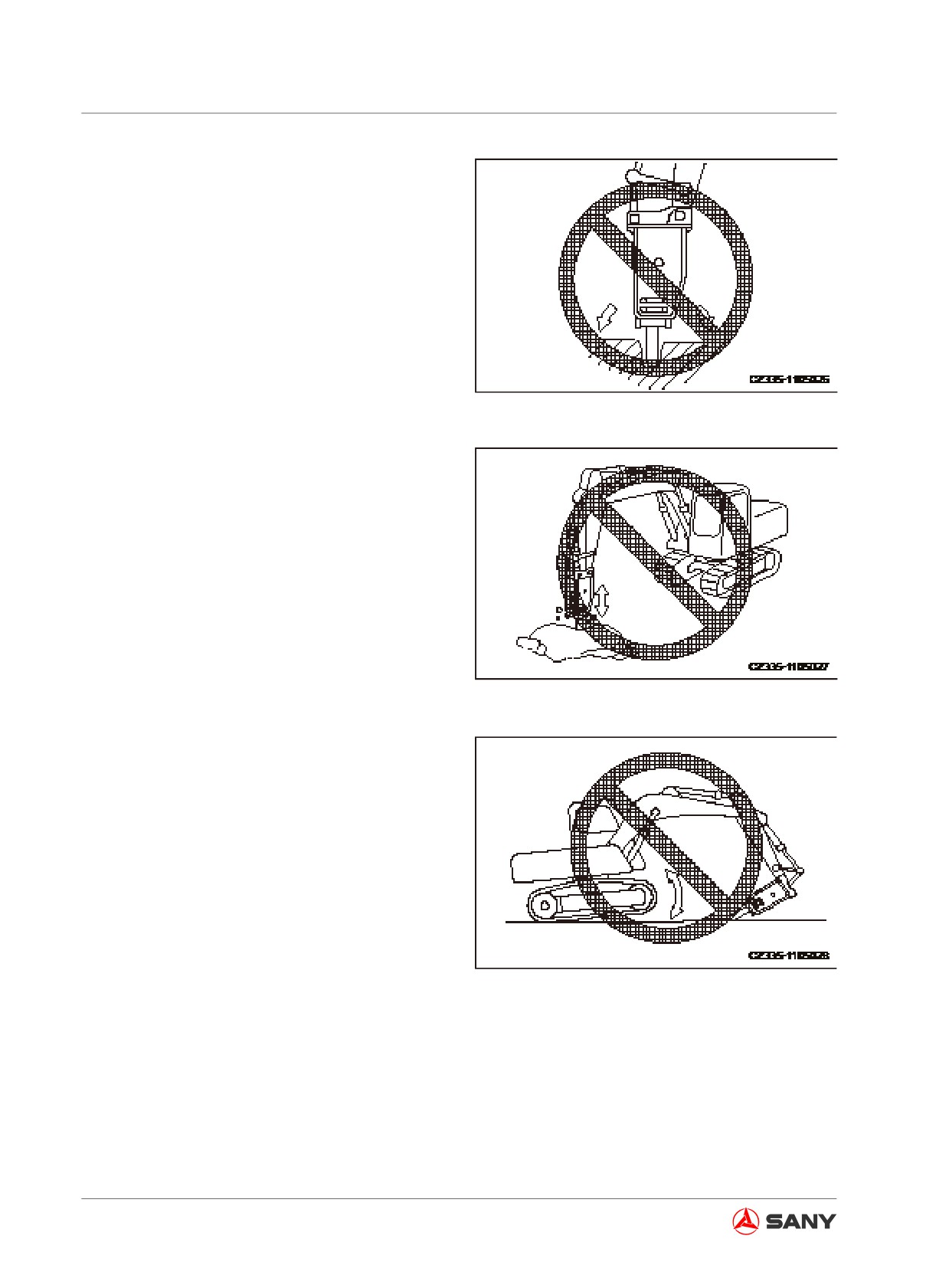
8.5 Restricted Operations
Do not operate your machine in any of the fol-
lowing manners in order to ensure a longer
service life and safe operation.
● Do not operate any of the oil cylinders to
its full stroke. A distance of 5 cm (2 in) is to
be reserved for backup.
1. Accumulating rocks with the breaker.
Fig. 8-28
8-22
Optional Equipment
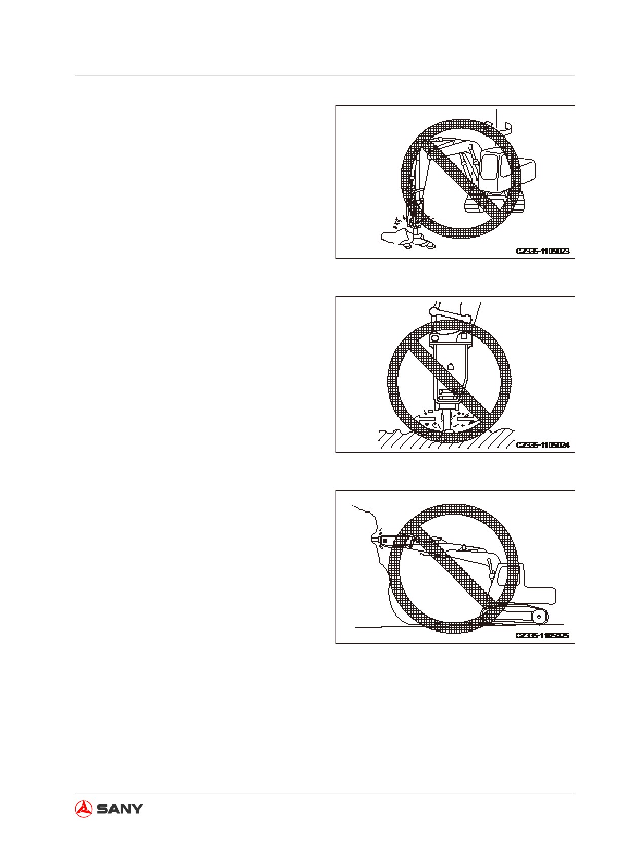
2. Breaking with swinging force.
Fig. 8-29
3. Moving the chisel during striking operation.
Fig. 8-30
4. Keep the chisel level or upward during
striking operation.
Fig. 8-31
8-23
Optional Equipment
5. Swing the chisel when the rock has been
penetrated.
Fig. 8-32
6. Pecking operation.
Fig. 8-33
7. Raise your machine above ground by fully
extending the bucket cylinder and by the
pushing force.
Fig. 8-34
8-24
Optional Equipment
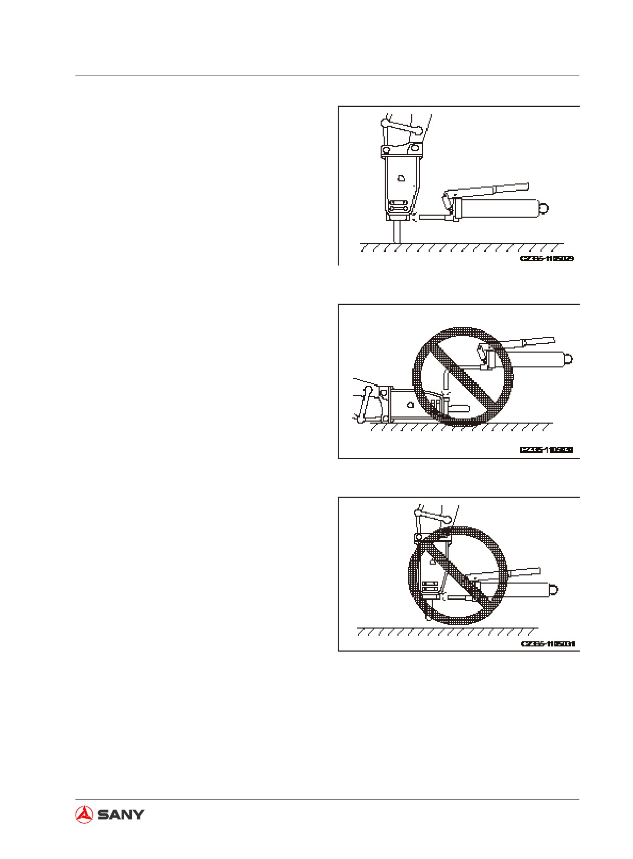
8.6 Hydraulic Breaker Lubrication
Grease the breaker at the correct point.
Fig. 8-35
Note:
Greasing in an improper manner could add
grease more than desired. As a result, soil and
sand may enter the hydraulic system, which
can damage the hydraulic components when
using the breaker.
Fig. 8-36
Fig. 8-37
8-25
Optional Equipment
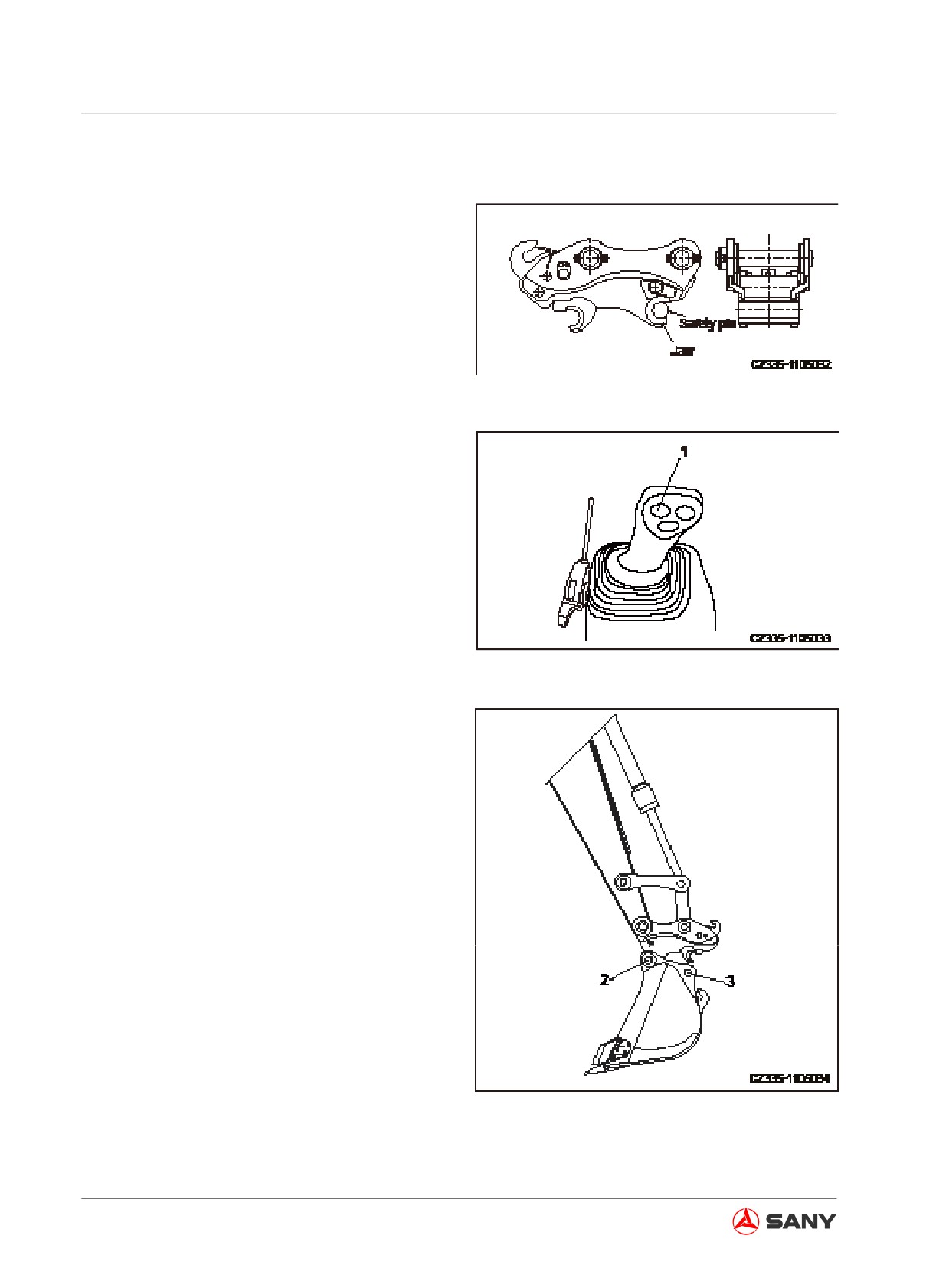
8.7 Quick Coupler and Control System
8.7.1 Quick coupler installation
1. Remove the safety pin of quick coupler, as
shown in the right illustration.
Fig. 8-38
2. Depress the quick coupler operation button
(1) (auto reset) on the left joystick in order
to slowly reduce the opening of the flexible
jaws and the fixed jaws of quick coupler.
Fig. 8-39
3. Make the quick coupler's fixed jaws to
slowly grip the bucket's support pin (2), as
shown in the right illustration.
Fig. 8-40
8-26
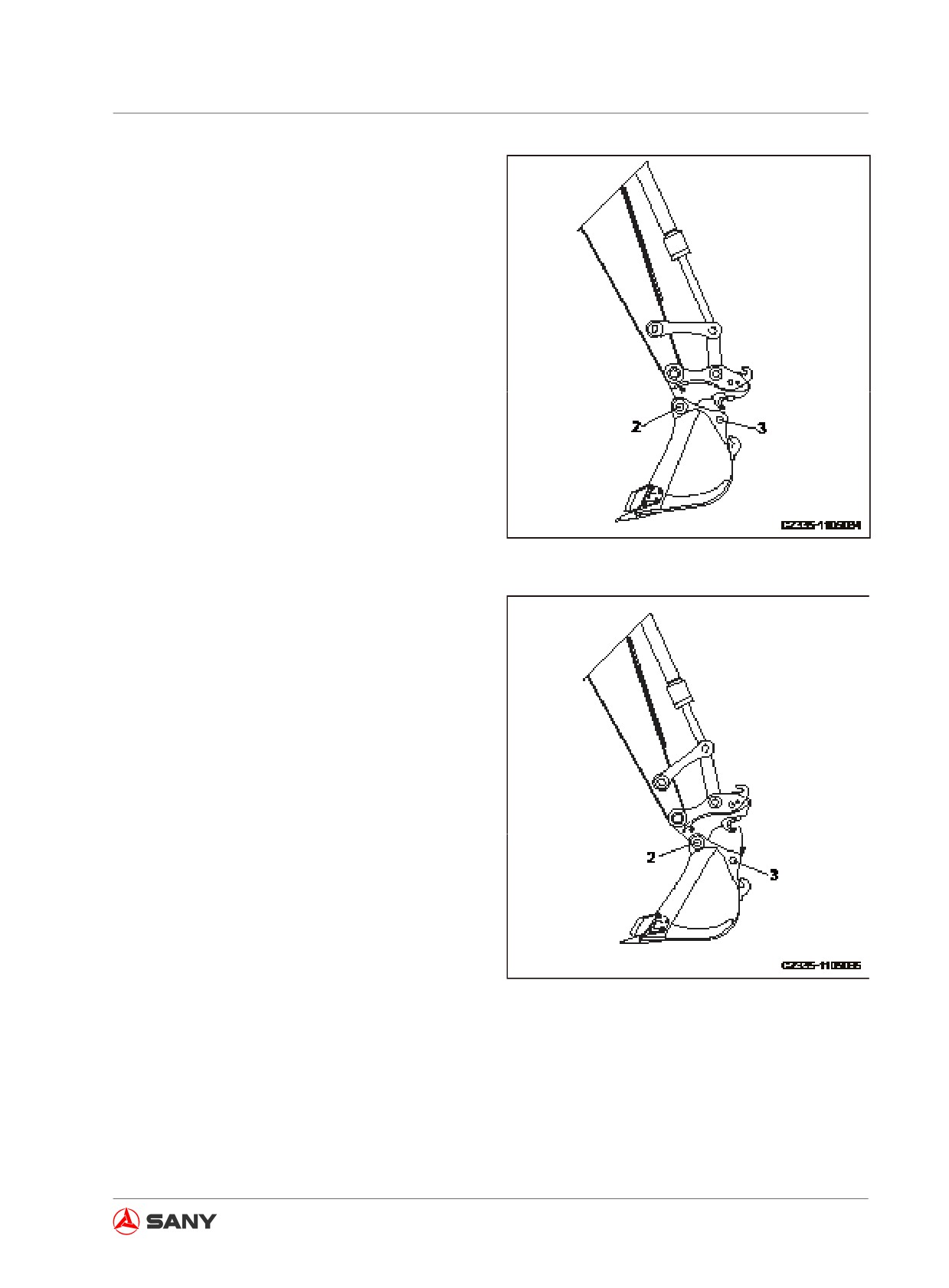
Optional Equipment
4. Extend the bucket cylinder to slowly move
the flexible jaws of quick coupler toward
the bucket's support pin (3).
Fig. 8-41
5. Make sure that the jaws of quick coupler
grip completely the support pin (3) of the
bucket.
Fig. 8-42
8-27
Optional Equipment
6. Release the operation button of quick
coupler in order to enable the quick cou-
pler to grip the bucket's support pin before
conducting other operations.
7. Insert the safety pin after installation.
Fig. 8-43
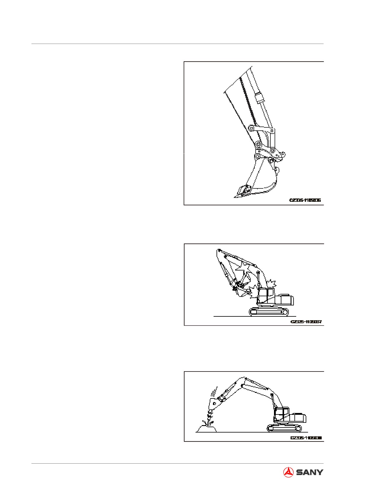
8.7.2 Operating precautions
1. After installation of the quick coupler, the
bucket and other optional equipment will
make the swing diameter longer during the
operation. In this case, they could possibly
impact the cab or boom of your excavator.
So be careful with the operation. After the
quick coupler has been installed, retract
the bucket to its position (the bucket
cylinder is fully extended) before retracting
the arm when carrying out retracting the
operation. To avoid damaging the boom,
Fig. 8-44
never retract the arm to its position (the
arm cylinder is fully extended) before
operating the bucket.
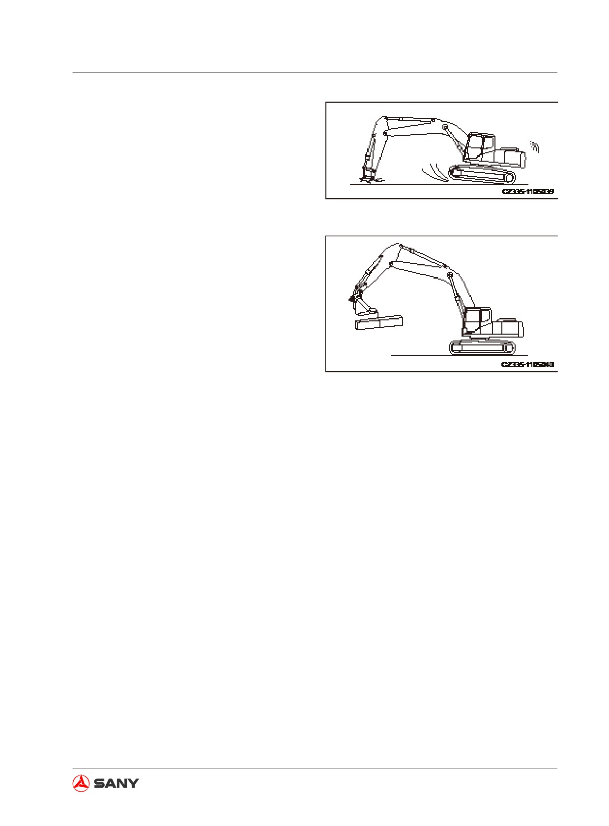
2. Overloaded preparation may impair your
machine and its optional equipment, thus
reducing their service life.
Fig. 8-45
8-28
Optional Equipment
3. Do not apply pressure when the quick cou-
pler touches the ground. Use the coupler
only when it is connected with the bucket
or optional equipment.
Fig. 8-46
4. It is very dangerous to move a heavy
object with the quick coupler. Meanwhile,
the service life of quick coupler could be
reduced.
Note:
Consult Sany local authorized dealer if you
need to install a quick coupler. Make sure that
you are using an optional equipment that has
Fig. 8-47
been approved by Sany. Sany assumes no re-
sponsibility for any failure and accident result-
ed from installation of any optional equipment
that has not been approved by Sany.
8.8 Refueling System
8.8.1 Introduction
Sany excavators are equipped with a fueling
system, which uses a refueling pump assem-
bly. The refueling pump assembly is intended
specially for large mobile off-the-road machin-
ery, vehicles and vessels. It uses on-board
battery as the power source and is not limited
by terrain and power supply, which makes it
very suitable for construction side and field.
For information regarding refueling amount,
see“Fluid capacities” on page 5-19.
8-29
Optional Equipment
8.8.2 Components
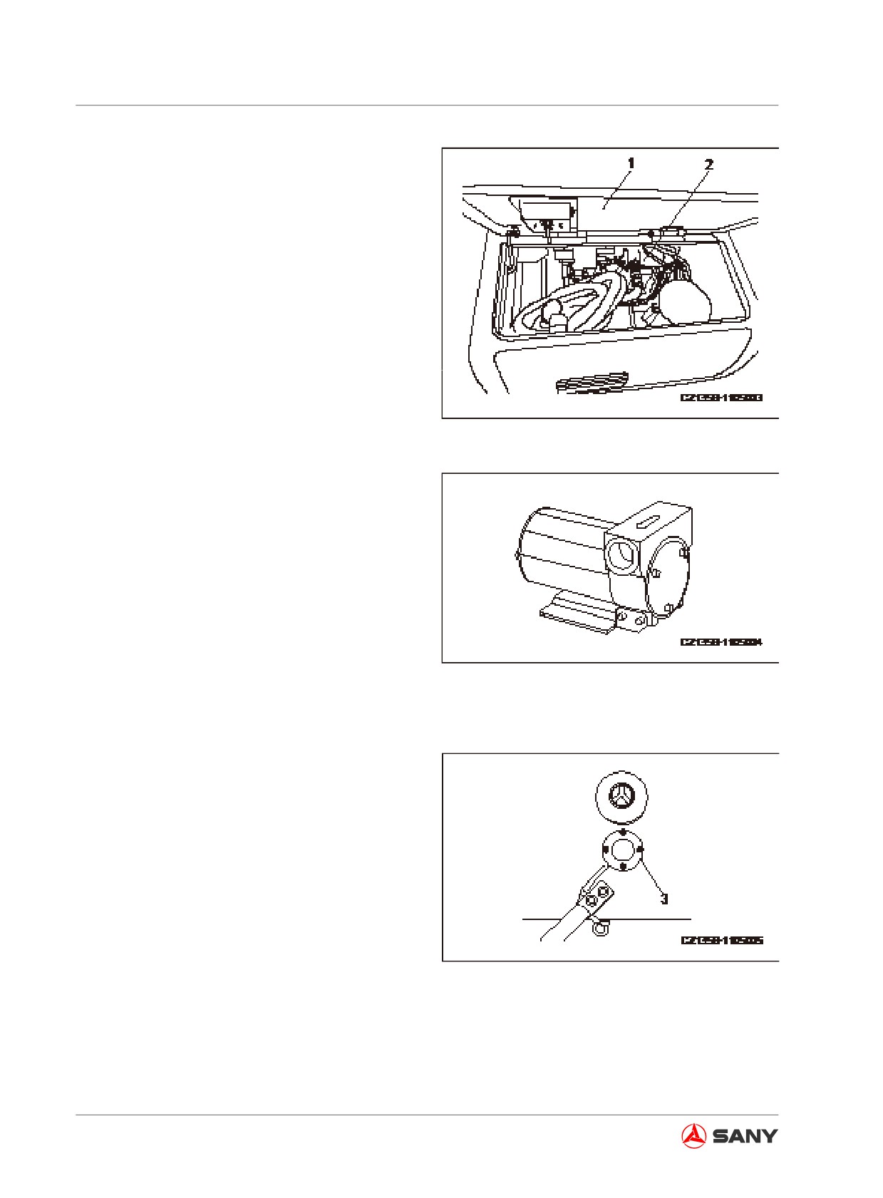
● The fueling system of Sany excavators in-
cludes mainly: a refueling pump assembly
(including relevant piping and valves), a
control switch and a fuel level control relay.
● Open the battery cover (1) and you can
see the control switch and the refueling
pump (2).
Fig.
8-48
●
The main structure of the refueling pump 2)
is shown in the right illustration.
●
Technical specifications of the refueling
pump:
Pump flow rate: 46L/min
Rated voltage: 24V
Rate speed: 2800 rpm
Coupling thread: 3/4’G
Fig.
8-49
Weight: 3.5kg
Packing dimension: 215×120×160mm
●
The fuel level control relay (3) is shown in
the right illustration.
This relay is installed in front of the fuel
tank filler opening and is connected with
the refueling pump control switch and re-
lay. Its signaling position is 100mm from
the tank top surface.
Fig. 8-50
8-30
Optional Equipment
8.9 Central Lubrication System
8.9.1 Scheme and components
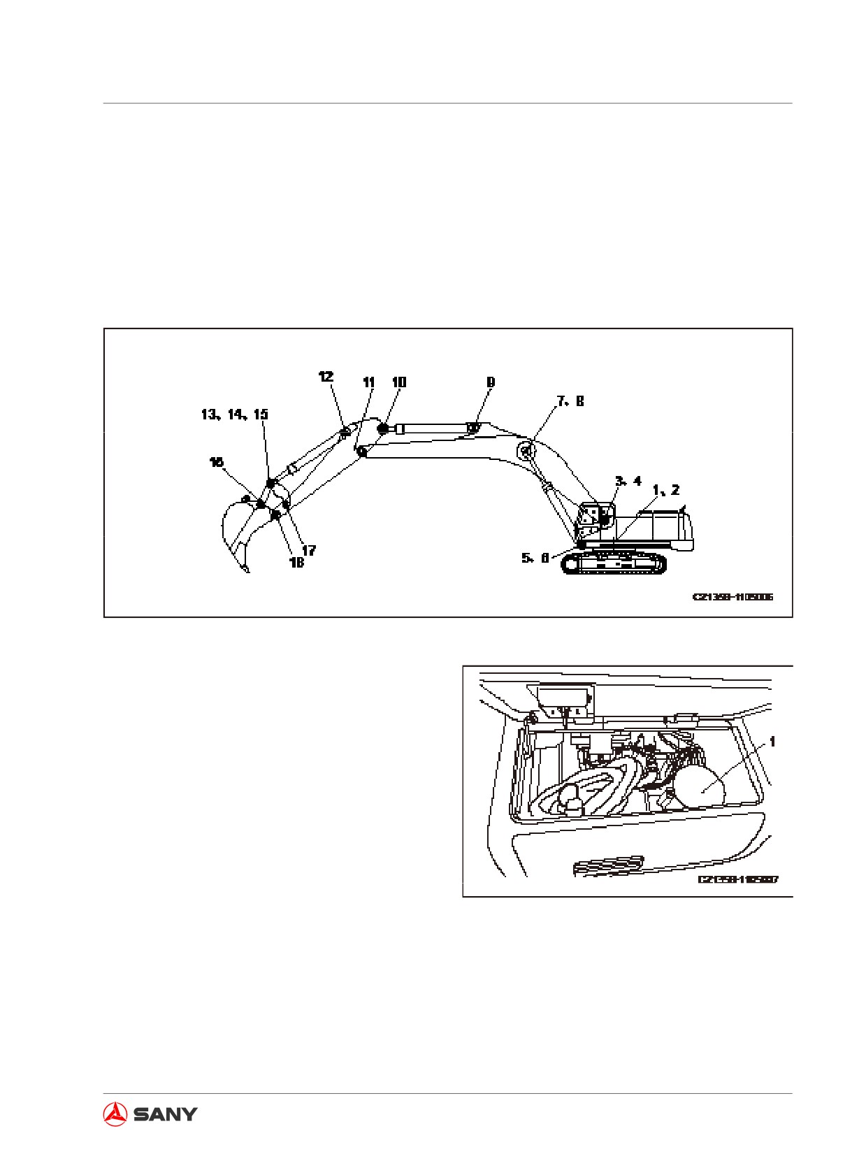
1. Models SY115C9, SY135C8/9 and SY155H adopt a 18-point lubrication scheme.
A sketch on distribution of excavator lubricating points is shown below:
Fig. 8-51
2. System components
● Electric grease pumping section
It is composed of the pump-mounting
base, the electric pump, the pumping unit,
the safety valve and the filter.
Fig. 8-52
8-31
Optional Equipment
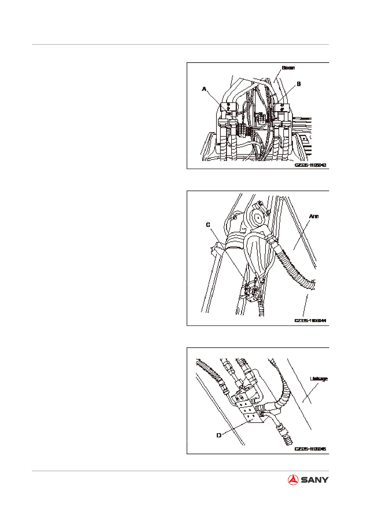
● Distributor section
System distributor is mainly composed of:
Main distributor (1)
MX-F3/3
Secondary distributors (3)
MX-F510
MX-F3/5
MX-F3/4
Fig. 8-53
The main distributor (A) and the secondary
distributor (B) installed to the boom root
are shown in the right illustration.
Secondary distributor (C) mounted to the
arm.
Fig. 8-54
Secondary distributor (D) mounted to the
inside of the linking rod.
● Major lines configuration
The system's major lines include high-
pressure hoses, straight connectors, el-
bows, straight expansion core, bent expan-
sion core, steel wire protection sleeves,
hose protection sleeves, bucket distributor
protection plates, etc.
Fig. 8-55
8-32
Optional Equipment
8.9.2 System working principle
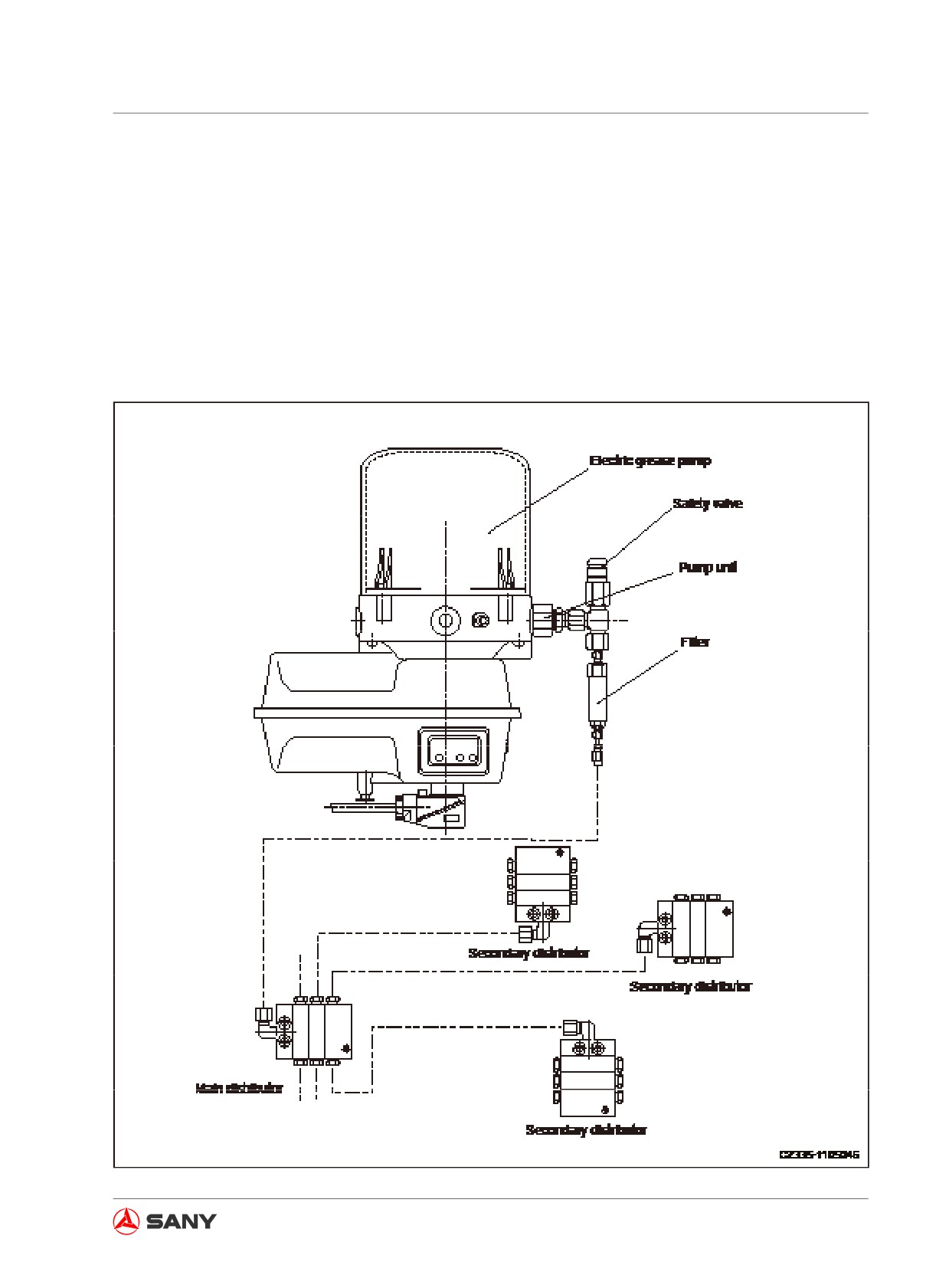
As Sany SY series excavators have a relatively central distribution of lubricating points that are
close to each other, we choose to use a progressive central lubrication system which is shown in
the illustration below.
Operating principle: The pressurized grease from the electric plunger pump goes through the
pumping unit, safety valve and filter to the main distributor, where the grease is sent through the
tubes to three secondary distributors and then supplied in turn to each lubricating point according
to a certain proportion.
Fig. 8-56
8-33
Optional Equipment
8.9.3 Setting the lubrication time of electric grease pump
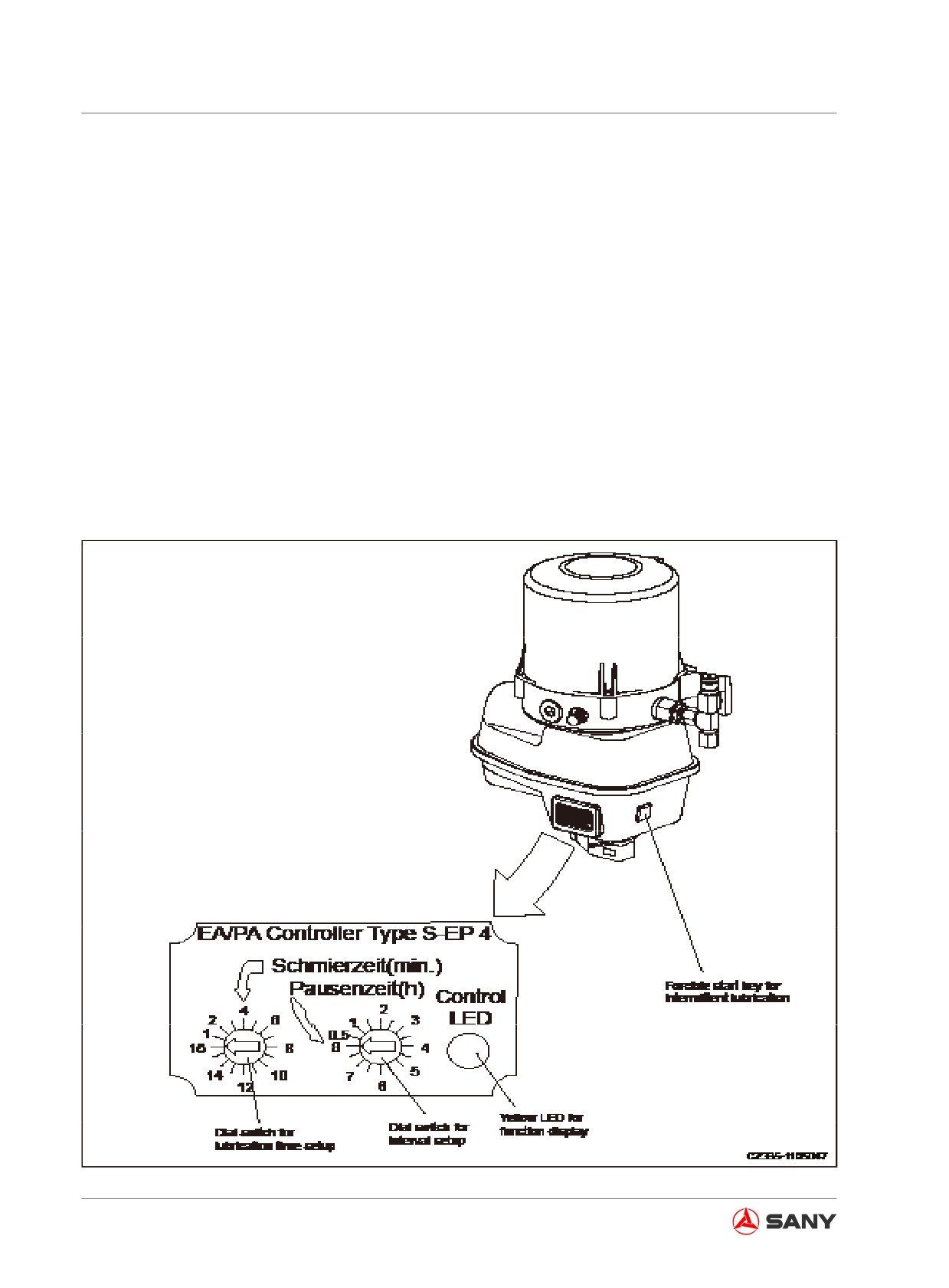
The electronic controller built in the electric grease pump can realize related control over the
time or cycle of the central lubrication system. When the time programming control is applied,
the cab's central lubrication system indicator flashes after the excavator is powered on; the yel-
low LED indicator of the electronic controller will be illuminated for 25 seconds, indicating that the
system is ready for lubrication.
By pressing the start button on the motor's shell or instrument panel, the lubrication cycle begins.
Upon completion of the lubrication cycle, the motor of lubricating pump stops and the shutdown
cycle begins. Subsequent lubrication will start according to the predetermine time schedule. If the
engine is shut off during shutdown period or lubrication cycle, the cycle will be terminated and the
time period will be recorded. When the engine is started again, the lubrication cycle will continue
counting the time from when the previous cycle is terminated. For the suspended lubrication cy-
cle, pressing the forcible start button allows you to activate the lubricant pump. Once the control
unit is energized, a lubrication cycle will be activated. The following illustration shows the panel of
electronic controller of the grease pump.
Fig. 8-57
8-34
Optional Equipment
● Setting the parameters
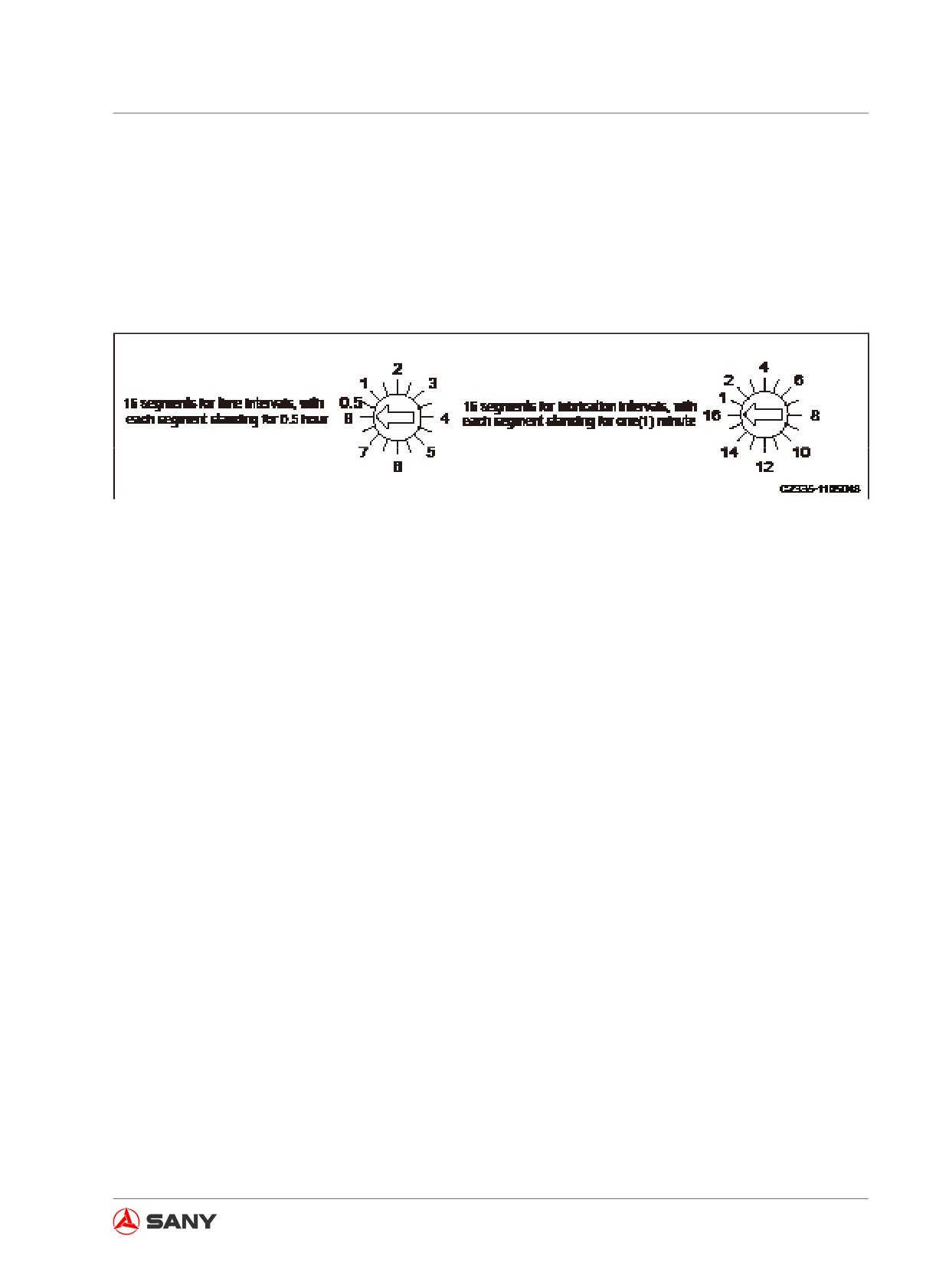
The interval can be set to 0.5 - 8 hours; the lubrication cycle can be set to 1 - 16 minutes, as
shown in the illustration below. If you need to adjust the time, use a flat-headed screw driver
to disassemble the red edge frame, loosen the four cross-headed screws, and remove the
transparent covers in turn. If any of the covers is not shut properly, water could penetrate into
the control unit and damage may result in.
Fig. 8-58
8.9.4 Technical description
1. The system will lubricate for 10 minutes every half an hour, which was set at the factory
before delivery.
2. After operating for 100 hours, you can adjust (increase or decrease) the lubricating time ac-
cording to actual condition. The lubricating interval, however, shall not be changed.
3. Clean lithium base grease NLG12# is recommended for the lubrication.
4. Electric lubricant pump (24V/DC, 19 kg) with built-in electronic controller is used.
8-35
Optional Equipment
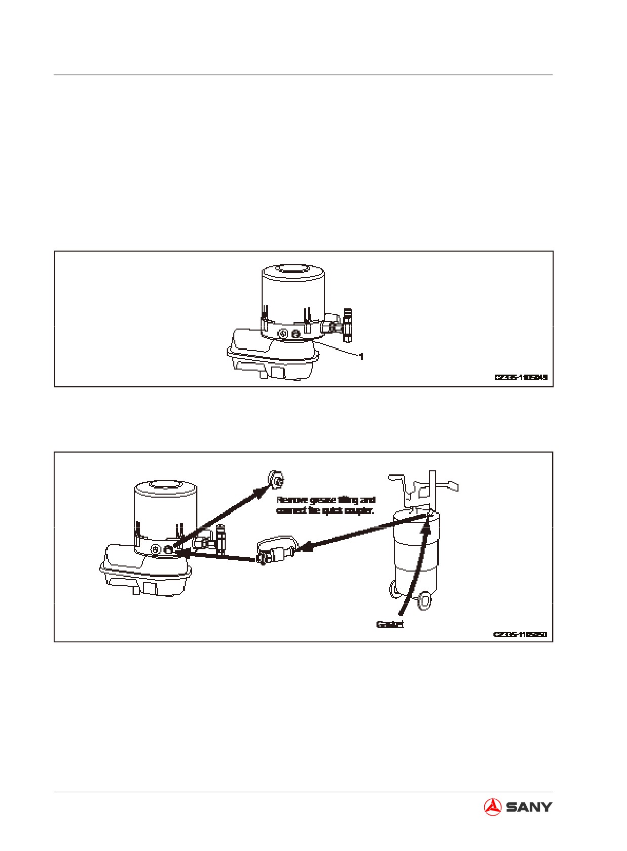
8.9.5 Adding grease with electric pump
The electric grease pump of the central lubrication system lubricates your machine in the follow-
ing three ways.
1. Standard Method:
Manual or pneumatic grease gun is used to add grease through the ball-type nozzle (1), as
shown in the following illustration.
Fig. 8-59
2. Add grease through the connector, as shown in the illustration below.
Fig. 8-60
8-36
Optional Equipment
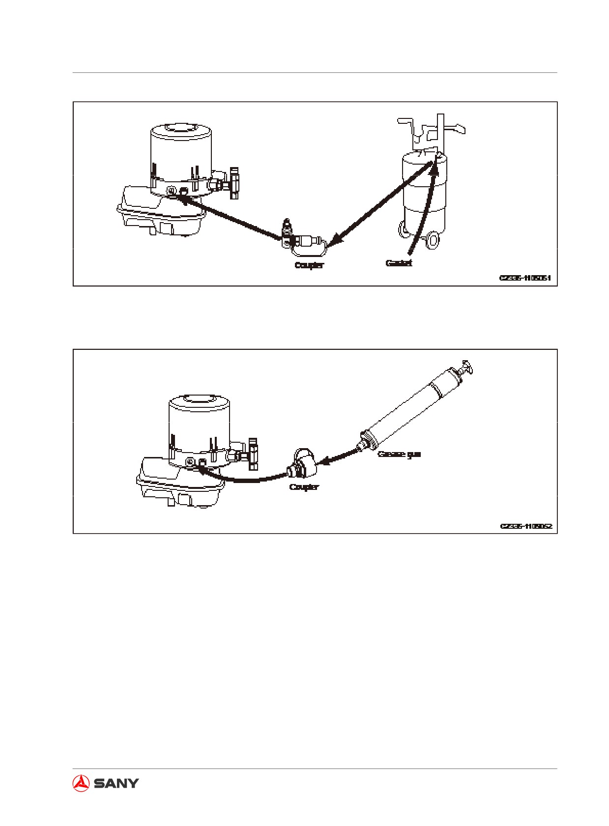
Fig. 8-61
3. Add grease through the grease gun, as shown in the illustration below.
Fig. 8-62
Note:
Please consult Sany distributor if you need to install the central lubrication system. Make sure
that you are using accessories specified by Sany. Sany assumes no responsibility for failures and
accidents caused by the installation of any accessories that have not been approved by Sany.
8-37