SANY Crawler Hydraulic Excavator SY115C9/135C/155H. Operation and Maintenance Manual - page 8
Maintenance
2. Hold the primary air cleaner element (5),
shake it slightly and turn it in both direc-
tions in order to pull it out.
3. After removing the primary air cleaner ele-
ment (5), check the secondary air cleaner
element to see if it displaces or tilts. Push
it back to position in case of displacement
or tilting.
4. After removal of the primary air cleaner
element (5), use clean cloth or tape to
cover the secondary air cleaner element (6)
in order to prevent entering of dirt.
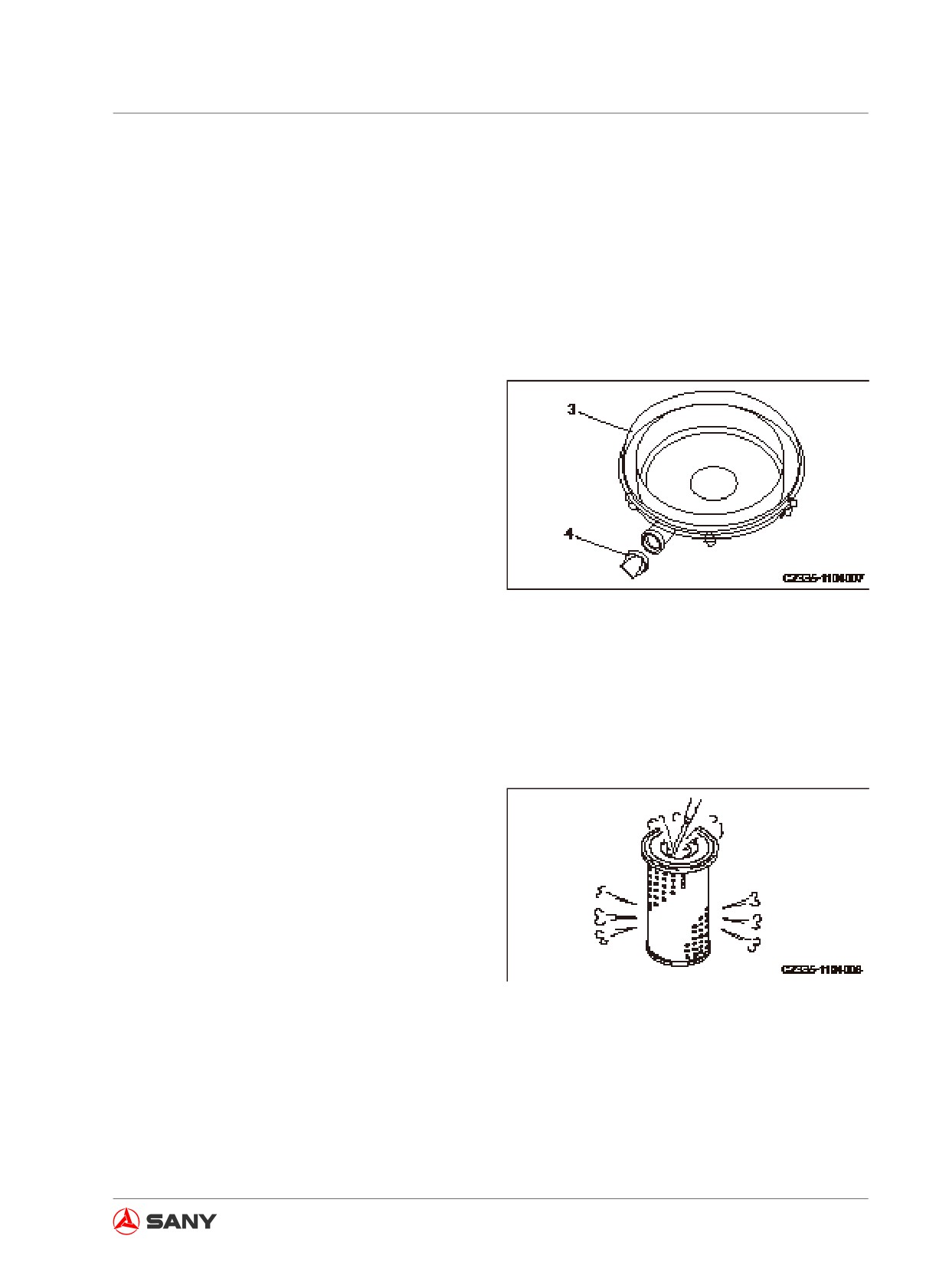
5. Wipe or brush off the dirt from the cover (3)
and the inside of air cleaner housing (1).
6. Wipe off the dirt built up on the cover (3)
and the vacuum valve (4).
Fig. 5-7
Note:
Never tap the air filter with any object when
cleaning it.
7. Use dry compressed air (less than 0.69
MPa (7kgf/cm2) 99.4 PSI)) to blow along
the inside of the pleats toward the primary
air cleaner element, and then direct the
compressed air along the outside of the
pleats to blow from interior to exterior.
1) Replace the primary air cleaner ele-
ments that have been cleaned six times
or used for more than a year. Replace
Fig. 5-8
the secondary air cleaner element at the
same time.
2) Remove one of the tags from the filter
after each cleaning.
5-31
Maintenance
8. Use a light to illuminate the whole primary
air cleaner element. Replace the primary
air cleaner element in case of holes or
reduced thickness found in the filter mate-
rial.
9. Remove the cloth or tape covering the
inner filter element (6).
Note:
Fig. 5-9
● Never use air cleaner elements with dam-
aged pleats, gaskets or seals.
● Using a filter that has been used for more
than a year or an O-ring that has been
cleaned could result failure. Never use
them again.
10. Check the new filter or the cleaned filter for
dirt or oil stains on the sealing area. Wipe
off the dirt or oil stains.
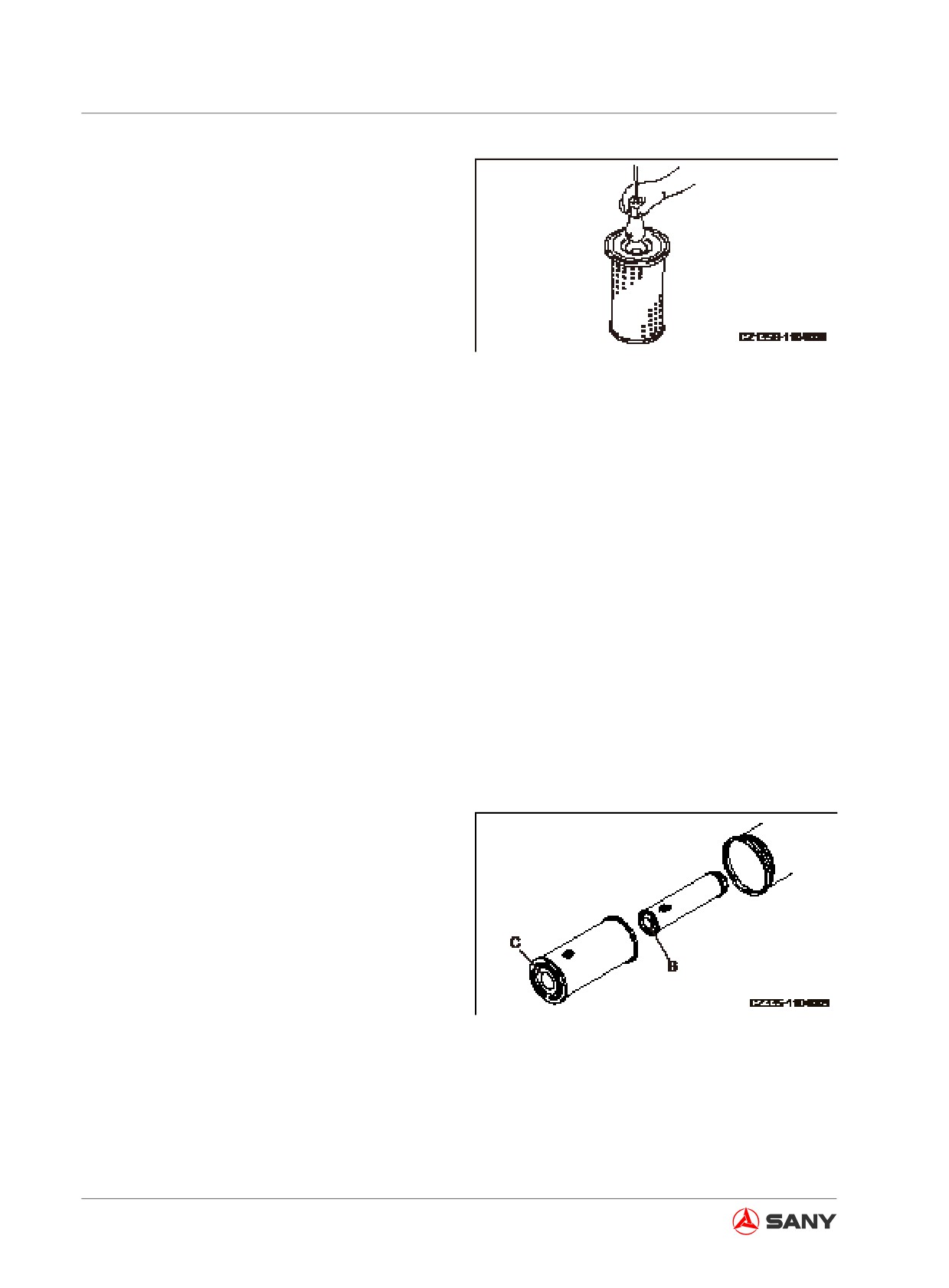
11. Push the primary air cleaner element
straight forward into the air cleaner hous-
ing. You can hold the primary air cleaner
element and shake it slightly in order to
insert the primary air cleaner element eas-
ily.
Note:
The air cleaner must be reinstalled correctly.
Make sure that the air cleaner cartridge's bot-
tom (the end without opening) (B) (C) faces
the cover (3). Incorrect installation could result
in air filter damage and engine damage.
Fig. 5-10
5-32
Maintenance
Note:
The latches (2) and housing of air cleaner
could be damaged when you insert filter ele-
ment with expanded rubber on the top or you
did not push it in vertically but latch the cover
(3) with force. So be careful when you reas-
semble filter element.
Fig. 5-11
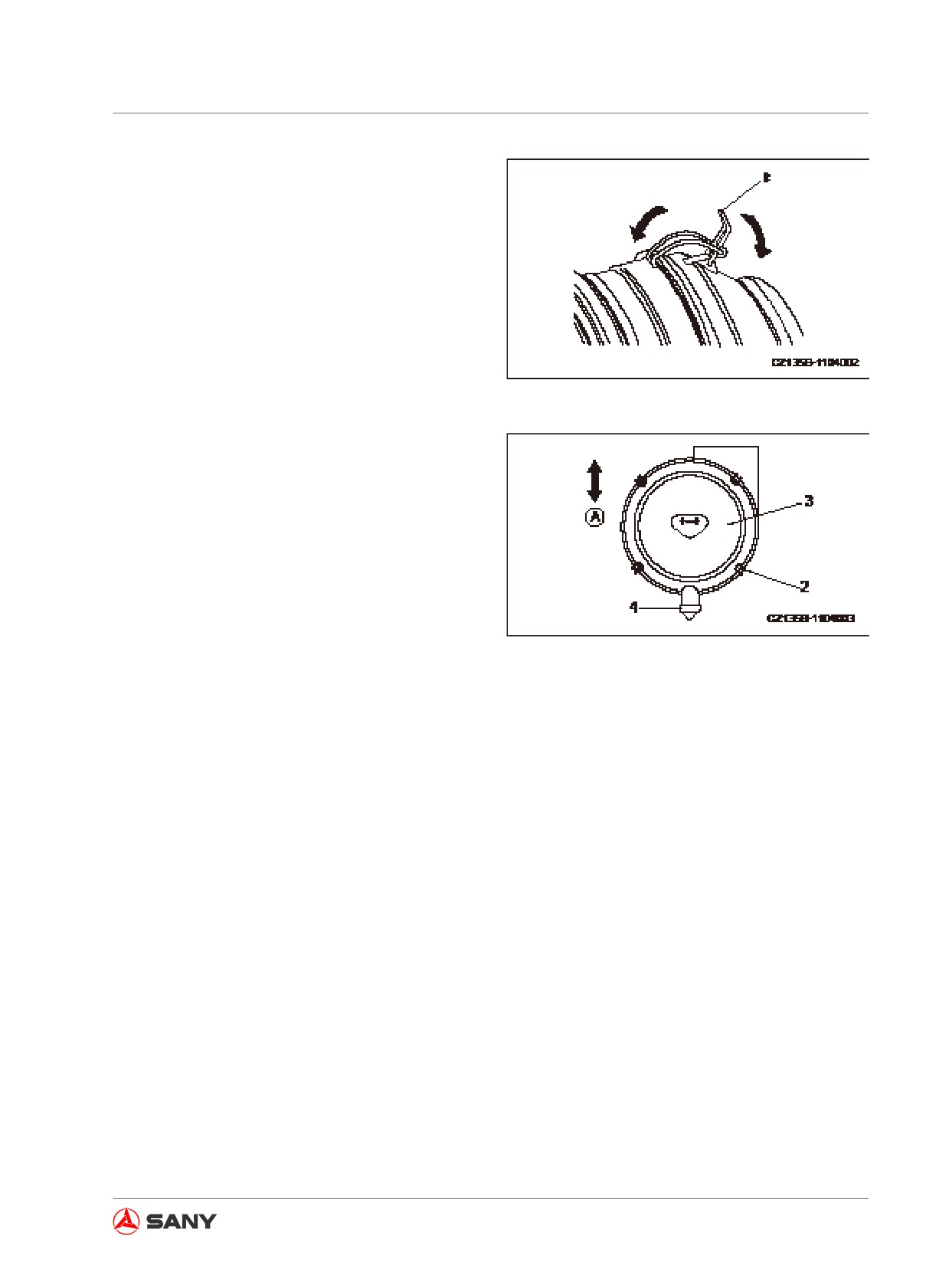
12. Install the cover (3) according to the follow-
ing steps.
1) Align the cover (3) with the filter.
2) Let the end of latch (2) catch the flange
of the air cleaner housing.
3) To lock the latches (2), engage the
latches in a diagonal sequence (top -
Fig. 5-12
bottom - left - right) like tightening the
bolts.
4) The vacuum valve (4) shall face toward
the ground (A) when installing the cover
(3).
5) When the cover (3) is installed, inspect
the air cleaner housing shall not have
a larger clearance with the cover (3).
Reinstallation is necessary in case of
larger clearance.
5-33
Maintenance
Replacing filter elements
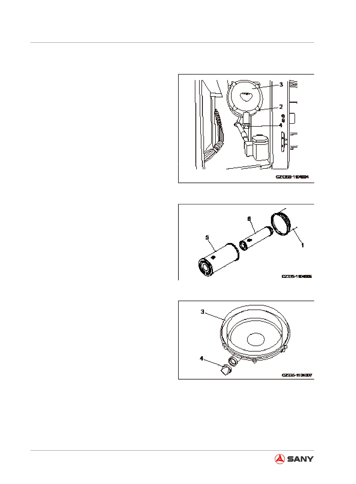
1. Open the left rear door of the machine and
loosen the four latches (2) before removing
the cover (3).
Fig. 5-14
2. Hold the outer filter element (5), shake
it slightly and turn it in both directions in
order to pull it out. Never remove the inner
filter element (6).
3. After removing the outer filter element (5),
check the inner filter element to see if it
displaces or tilts. Push it back to position in
case of displacement or tilting.
Fig. 5-15
4. Wipe or brush off the dirt from the cover (3)
and the inside of air filter housing (1).
5. Wipe off the dirt built up on the cover (3)
and the vacuum valve (4).
Fig. 5-13
5-34
Maintenance
Note:
●
Never use the inner filter element after
cleaning it. Replace the inner filter element
while the outer filter element is replaced.
●
When the outer filter element and the cover
have been installed, improper installation
of the inner filter element could damage
the outer filter element.
●
Fake parts will allow dirt to pass through
and damage the engine due to insufficient
precision in the sealing area. Therefore,
fake parts shall not be used under any cir-
cumstances.
6.
Remove the secondary air cleaner element
(6) and install a new secondary air cleaner
element immediately.
Insert the secondary air cleaner element
securely.
7.
Push the primary air cleaner element (5)
straightly into the air cleaner housing.
When pushing the primary air cleaner ele-
ment, you may hold the primary air cleaner
element and shake it slightly in order to
make the insertion easily.
Note:
The air cleaner must be reinstalled correctly.
Make sure that the air cleaner cartridge's bot-
tom (the end without opening) (B) (C) faces
the cover (3). Incorrect installation could result
in air filter damage and engine damage.
Fig. 5-16
5-35
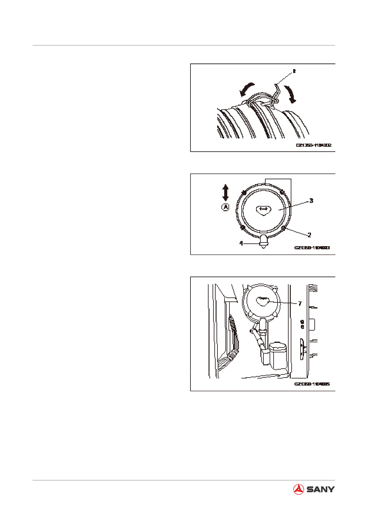
Maintenance
Note:
The latches (2) and housing of air cleaner
could be damaged when you insert filter ele-
ment with expanded rubber on the top or you
did not push it in vertically but latch the cover
(3) with force. So be careful when you reas-
semble filter element.
Fig. 5-17
8.
Install the filter cover (3) through the fol-
lowing steps.
1) Align the cover (3) with the filter.
2) Let the end of latch (2) catch the flange
of the air cleaner housing.
3) To lock the latches (2), engage the
latches in a diagonal sequence (top -
Fig. 5-18
bottom - left - right) like tightening the
bolts.
4) The vacuum valve (4) shall face toward
the ground (A) when installing the cover
(3).
5) When the cover (3) is installed, inspect
the air cleaner housing shall not have
a larger clearance with the cover (3).
Reinstallation is necessary in case of
larger clearance.
9.
Use a new sticker to replace sticker (7) on
cover (3).
Fig. 5-19
5-36
Maintenance
5.8.2.2 Cooling system - clean
WARNING
● The radiator coolant is still hot under high pressure when the engine has just been
shut down. It is possible to burn if you remove the radiator cap to drain the coolant.
Remove the cap slowly to relieve pressure only when the cap is cool enough to touch
with your bare hand.
● When you start the engine for cleaning purpose, the hydraulic lockout control should
be placed in the LOCK position in order to prevent movement of the machine.
● For more information on startup of the engine See related sections in this manual.
● When disassembling the outer filter element, it is dangerous to pull it out with force.
Be careful when you are doing this job on an overhead surface or at where you are un-
able to stand firmly. Take care that the counter-acting force of pulling the outer filter
element could cause you to fall.
Always prepare your machine as required and lock/tag it out before proceeding. See “Preparing
the machine” on page 2-58 and “Lock-out and tag-out” on page 2-60.
Clean the inside of the cooling system and change the coolant according to the following table.
Interval for cleaning the inside of the cooling system and
Anti-freezing coolant
changing anti-freezing coolant
TEEC-L35 antifreeze
Every years or 2000 hours, whichever occurs first
Table 5-7
The coolant is also an important fluid against corrosion and freezing.
Anti-freezing coolant is also necessary in regions where freezing prevention is unnecessary.
Sany recommends TEEC-L35 antifreeze, which has excellent performance in anticorrosion, anti-
freezing and cooling, and can last for one year or 2000 hours.
We do not recommend you using other coolants. The use of other coolants is possible to erode
the engine and cooling system parts that made of light metal such as aluminum.
5-37
Maintenance
Sany recommends TEEC-L35 antifreeze. This antifreeze has a concentration of 50% and needs
no dilution.
If you buy antifreeze from the market, make sure that the antifreeze's concentration is within the
range 30-68% in order to ensure its performance against corrosion.
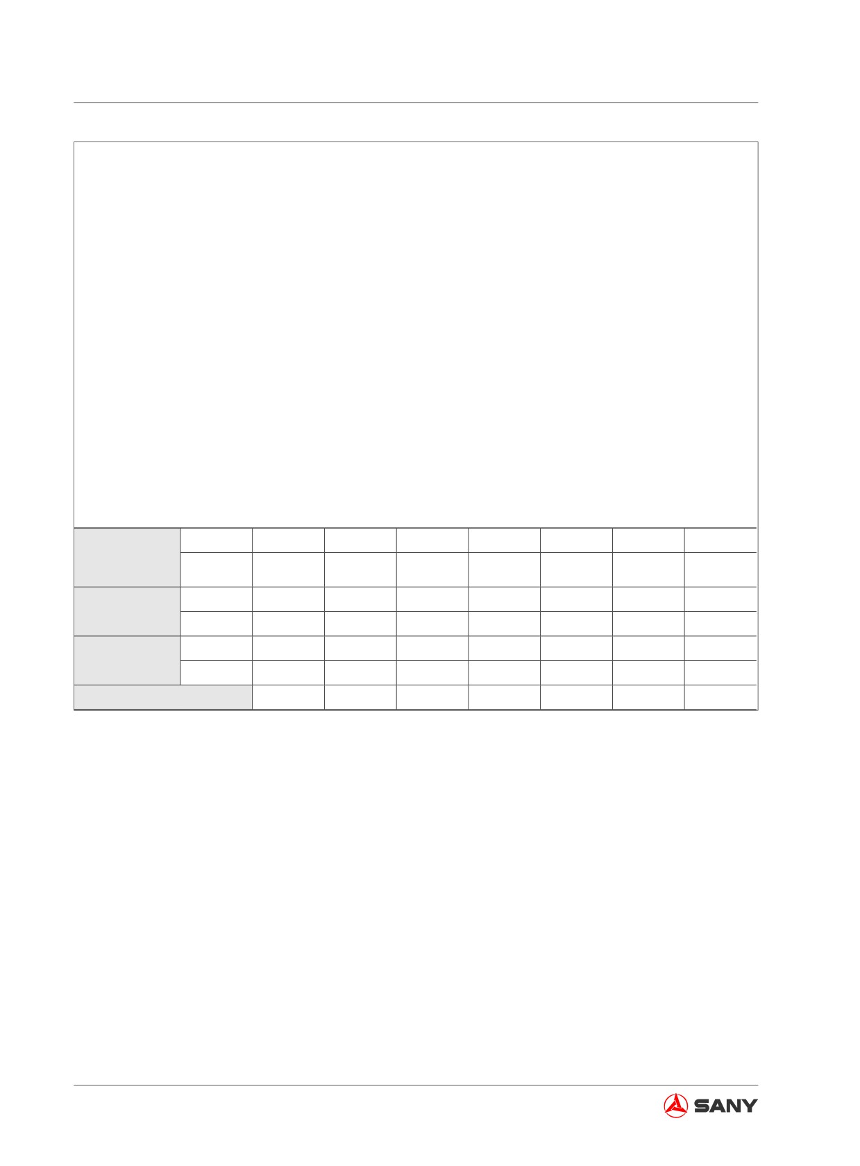
The ratio of mixing antifreeze with water is determined by the minimum ambient temperature, as
shown in the following table.
It is better to estimate 10℃ (18 ℉ ) lower than the actual temperature when selecting a mixture
ratio.
The mixture ratio is determined by ambient temperature. The mixture ratio shall not be lower than
30% (antifreeze/total volume of coolant ×100) in even the regions where freezing prevention is
unnecessary in order to prevent corrosion of the cooling system.
The undiluted antifreeze will freeze at -15 ℃ (5 ℉ ). Do not store the undiluted antifreeze in an
environment where is lower than -15℃ (5 ℉ ).
Minimum
℃
-10
-15
-20
-25
-30
-35
-40
atmospheric
℉
14
5
-4
-13
-22
-31
-40
temperature
L
6.75
8.1
9.23
10.35
11.25
12.15
13.05
Antifreeze
US gal
1.79
2.15
2.45
2.75
2.98
3.22
3.46
L
15.75
14.4
13.3
12.15
11.25
10.35
9.45
Water
US gal
4.18
3.82
3.53
3.22
2.98
2.75
2.51
Volume ratio (%)
30
36
41
46
50
54
58
Table 5-8
5-38
Maintenance
WARNING
● Antifreeze is flammable. Naked fire
should be kept away from antifreeze.
Antifreeze is poisonous. Be careful
when opening the drain valve in order
to prevent skin contract of the water
containing antifreeze. In case of con-
tact with your eyes, flush with large
amount of clean water and refer to
medical care immediately.
● To change the coolant or drain the ra-
diator coolant when repairing your ma-
chine, consult professional company
or your Sany distributor to dispose the
coolant containing antifreeze. Never
drain the coolant to sewage or onto
ground since the antifreeze is poison-
ous.
Use suitable water to dilute the antifreeze. (For
more information see“Coolant”on page 5-11.)
Density meter is recommended to control the
mixture ratio.
Prepare a container to hold the drained cool-
ant. The container's capacity should be larger
than the specific volume of coolant.
Prepare a hose to transfer anti-freezing cool-
ant and water.
1. Park your machine on a level ground and
then shut off the engine. Lock out and tag
out your machine before proceeding. See
“Lock-out and tag-out” on page 2-60.
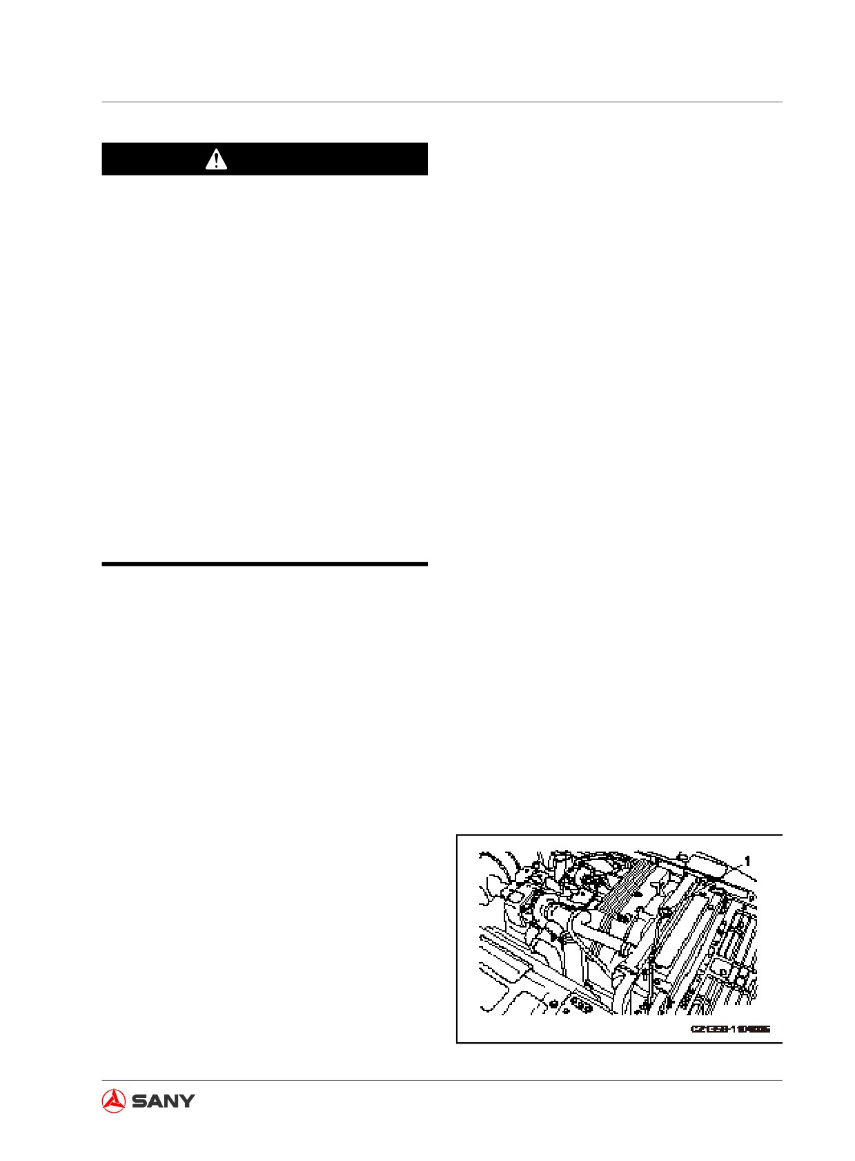
2. Remove slowly the radiator cap (1) to
relieve pressure only when the coolant is
cool enough for you to touch the radiator
cap with your bare hand.
Fig.
5-20
5-39
Maintenance
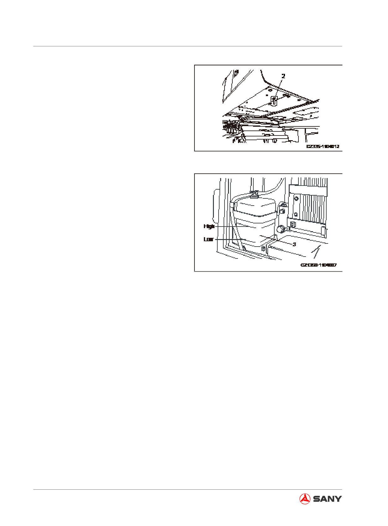
3.
Remove the bottom cap and place a con-
tainer to hold the coolant under the drain
valve (2).
Open the radiator bottom drain valve (2) to
drain the coolant.
4.
Close the drain valve (2) after draining
the coolant. Add tap water to the radiator.
When the radiator is full, start the engine
at low speed in order to heat up to 90
℃
Fig. 5-21
(194 ℉ )at minimum. Continue to run the
engine for about 10 minutes.
5.
Stop the engine and open the drain valve
(2) to discharge water.
6.
Use detergent to clean the radiator after
draining the water. Refer to the detergent
instruction for cleaning method.
7.
Close the drain valve (2).
8.
Reinstall the bottom cap.
Fig. 5-22
9.
Fill the coolant containing antifreeze till the
fluid overflows from the filler opening. The
mixture ratio of antifreeze and water is to
be determined according to the chart of
mixing values of antifreeze and coolant.
10. Run the engine at low speed for about five
minutes and then at high speed for five
minutes in order to eliminate the air from
the coolant. (The radiator cap (1) shall be
left open at the moment.)
11. Clean the auxiliary reservoir (3) after
completely draining the coolant from it. Add
water till the coolant level reaches a level
between the high and the low marks.
Replace the auxiliary tank with a new one
if the old one is hard to clean.
12. Stop the engine. Wait about three minutes
before adding water through the filler open-
ing. Screw on the radiator cap tightly.
5-40
Maintenance
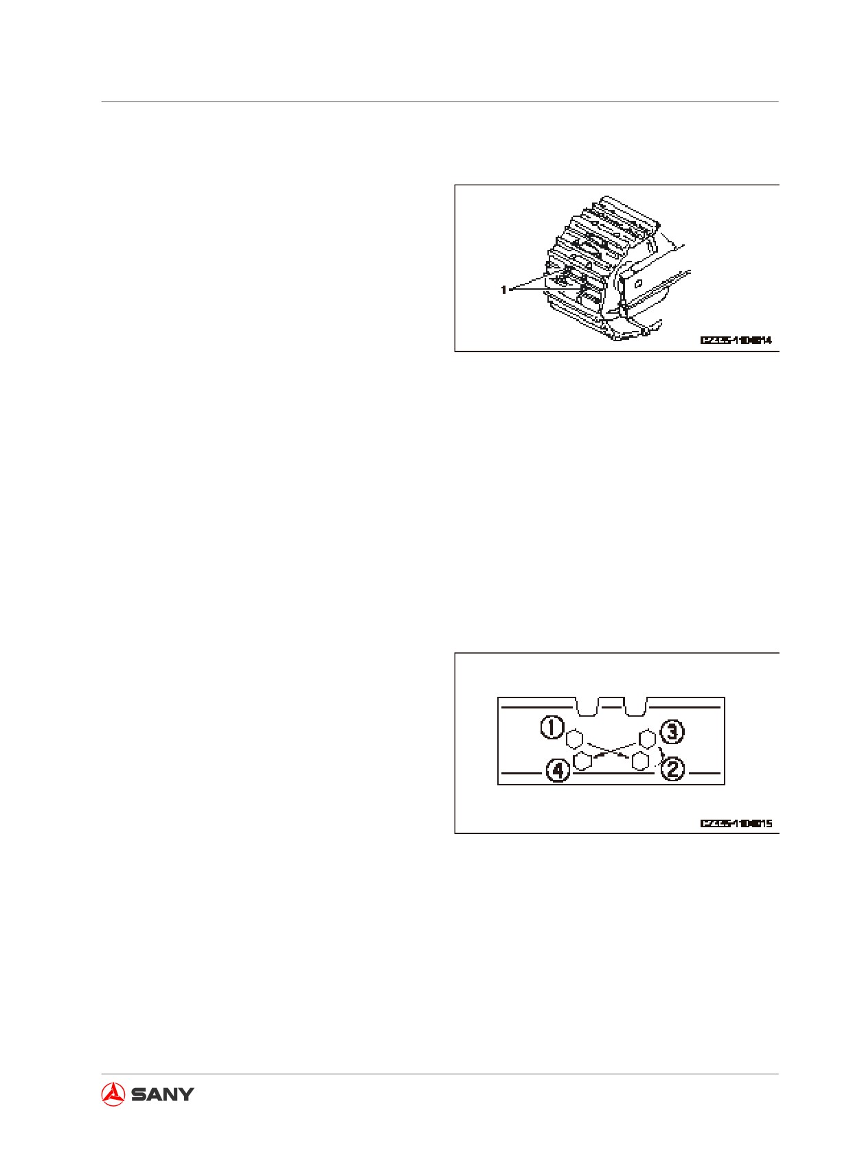
5.8.2.3 Track shoe bolts - inspect/tighten
If your machine is operated with loose track
shoe bolts (1), the bolts can break. Tighten
any loose bolts immediately.
Always prepare your machine as required
and lock/tag it out before proceeding. See
“Preparing the machine” on page 2-58 and
“Lock-out and tag-out” on page 2-60.
Tightening
Fig.
5-23
Three-grouser track shoe
1. Tighten the bolts to torque values of
600N·m - 680N·m (61.2kgf - 69.4kgf or
441Ibft - 500Ibft). Make sure that the nuts
and track shoe are in close contact with
the link mating surface.
2. Inspect and tighten again by 120º±10º.
Tightening sequence
Tighten the bolts in the sequence shown in the
right illustration. After tightening, make sure
that the nuts and track shoe are in close con-
tact with the link mating surface.
Fig. 5-24
5-41
Maintenance
5.8.2.4 Track tension - inspect/adjust
The wear of undercarriage pin rolls and pin
bushings may vary according to operating
condition and soil type. Therefore, the ten-
sion of track shall be checked often in order to
maintain standard tension.
Always prepare your machine as required
and lock/tag it out before proceeding. See
“Preparing the machine” on page 2-58 and
“Lock-out and tag-out” on page 2-60.
Inspection
1. Run the engine at low idle speed. Travel
the machine forward a distance that is
equivalent to the length of an unfolded
track. Park your machine.
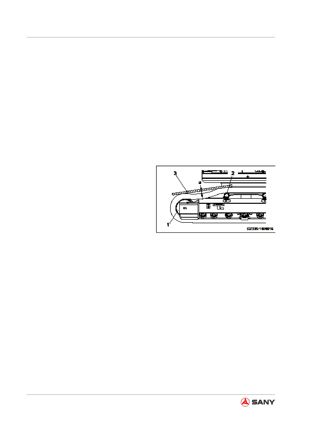
2. Place a straight edge on top of the track
grousers between the idler (1) and the
carrier roller (2), as shown in the right
illustration.
3. Measure the maximum amount of sag in
Fig.
5-25
the track. The sag is measured from the
highest point of the track grouser to the
bottom of the straight edge.
The standard value of sag (a) should be10
- 30 mm (0.4 -1.2in).
5-42
Maintenance
If the track tension is beyond the standard
range, adjust the track tension through the fol-
lowing procedure.
Adjustment
CAUTION
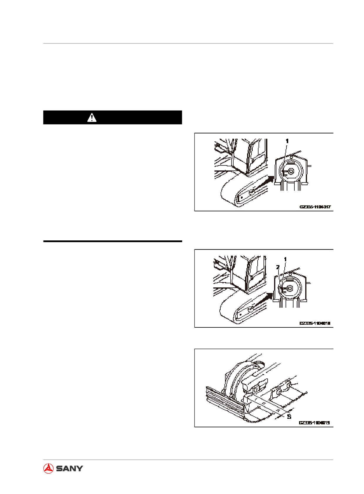
● The screw plug (1) is possible to fly out
under high-pressurized grease. Never
loosen the screw plug (1) over one
turn.
● Never loosen any other components
except the screw plug (1). Never face
the installation direction of the screw
plug (1).
● If the track does not loosen with the
following method, contact your Sany
Fig. 5-26
distributor.
Increasing track tension
To increase the track's tension, prepare a
grease gun.
1. Add grease with the grease gun through
the grease fitting (2). (The grease fitting (2)
and the screw plug (1) are integral.)
2. Slowly travel the machine forward (7-8 m
Fig.
5-27
(23 ft - 26 ft 3 in)) in order to check whether
the track tension is suitable.
3. Check the track tension again. Readjust
the tension if it is still beyond the standard
range.
4. Continue to add grease till the distance
(S) becomes null (0). If the tension is still
loose, it is probably because the pin roll
and bushing are overworn. The pin rolls or
bushings must be swapped or replaced.
Fig.
5-28
Contact your Sany distributor for repair.
5-43
Maintenance
Reducing track tension
WARNING
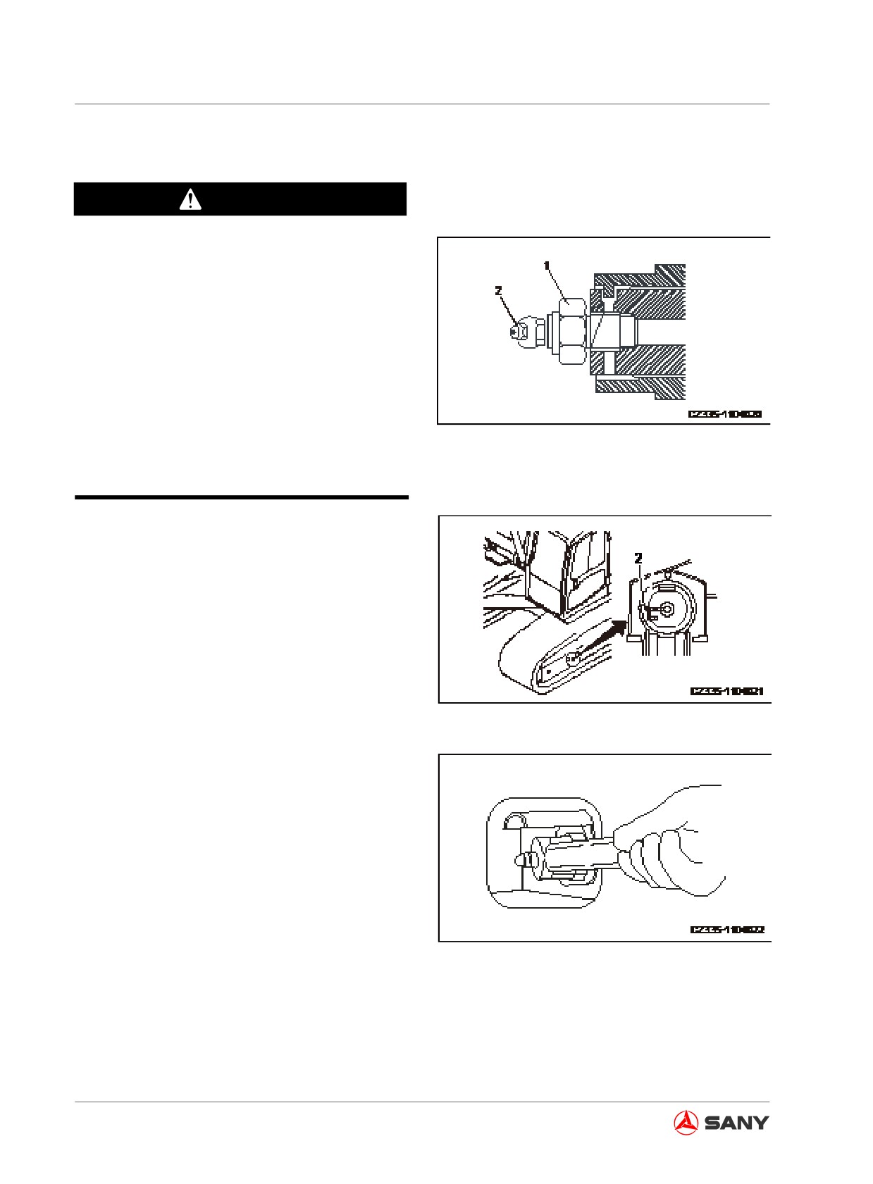
● Never loosen the valve (1) quickly or
excessively. The grease under pres-
sure can squirt out of the track tension-
ing cylinder. Carefully loosen the valve
(1) and keep your body and face away
from the valve (1).
● Never loosen the grease fitting (2).
● The grease is to be released through
the following steps. If the tension of
track is still tight, contact your Sany
Fig. 5-29
distributor for repair.
●
If gravels or mud falls between the sprock-
et and track link, remove it before you re-
duce track tension.
●
To reduce track tension, slowly turn valve
(1) counterclockwise with a long socket
wrench. The grease will come out of the
grease fitting.
●
Loosening valve (1) only one turn is
enough to reduce track tension.
Fig.
5-30
●
If grease does not come out smoothly,
drive your machine back and forth for a
short distance.
●
When suitable sag of track is achieved,
turn valve (1) clockwise to 78.4 N·m (8
kgf·m).
●
To check if you have got desired track
tension, run the engine at low idle speed,
drive your machine forward (at a distance
that is equivalent to the length of an un-
folded track), and then park the machine.
Fig.
5-31
●
Check track tension again. Readjust the
tension if it is still beyond the standard
range.
5-44
Maintenance
5.8.2.5 Bucket tips (lateral pin) - replace
Replace the bucket tip before the tip adapter
is worn.
WARNING
● Place the work equipment firmly before
replacing the bucket tips. Stop the en-
gine and engage the hydraulic lockout
control. If the hydraulic lockout control
is free, unexpected movement of the
work equipment could cause sever ac-
cident.
● If you drive the pin with great force, the
pin may fly out and cause an accident.
Keep irrelevant people a safe distance
from the area.
● Debris may fly out during replacement.
Always wear safety goggles, gloves
and other necessary protective gear.
Always prepare your machine as required
and lock/tag it out before proceeding. See
“Preparing the machine” on page 2-58 and
“Lock-out and tag-out” on page 2-60.
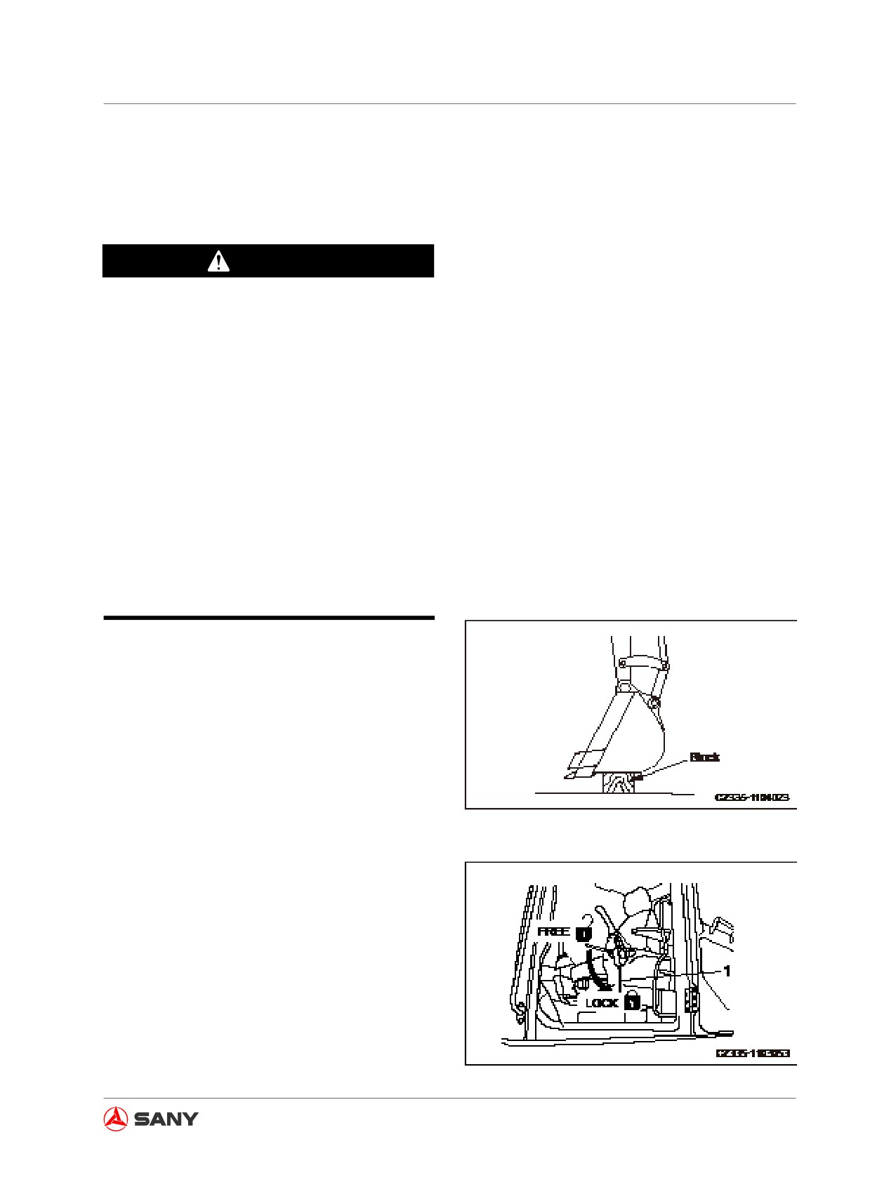
1. Place a block beneath the bucket in order
to remove the pin and keep the bucket
bottom leveling.
Fig. 5-32
2. Make sure the work equipment is stable
and the hydraulic lockout control is in
LOCK position.
Fig. 5-33
5-45
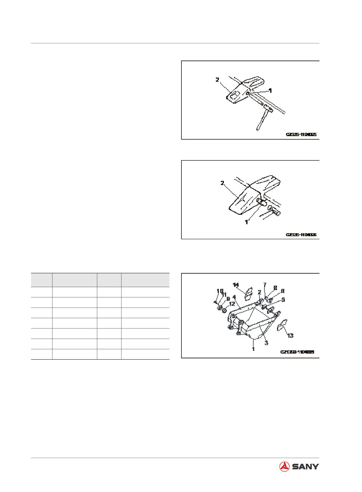
Maintenance
3. Place a metal stick against one end of the
pin (1) and hammer the metal stick in order
to drive the pin (1) out and remove the
bucket tip (2).
Remark:
● The metal stick shall have a smaller diam-
eter than the pin.
● If the tip cannot be removed safely in this
Fig. 5-34
way, consult Sany distributor for replace-
ment.
4. Remove the tip and check the latch for
any damage. Replace it if necessary.
The latches and tips worn short must be
replaced with new ones.
5. Clean the installation surface. Mount the
new bucket tip (2) to its adapter. Push part
of the pin (1) into the tip and hammer it in
completely in order to lock the bucket tip
Fig. 5-35
onto its adapter.
No.
Item
No.
Item
1
Bucket
8
Latch
2
Plate
9
Bush
3
Plate
10
Bolt
4
Plate
11
Washer
5
Adaptor
12
Spacer
6
Tip
13
Side cutter (left)
7
Pin
14
Side cutter (right)
Table 5-9
Fig. 5-36
5-46
Maintenance
5.8.2.6 Bucket Replacement
CAUTION
●
Driving a pin shaft with a hammer can
cause flying metal pieces that could
lead to severe injury. Wear goggles,
safety hat, protective gloves and other
protective gear during such an opera-
tion.
●
If the pin shaft is tapped with strong
force, it could fly out and cause per-
sonal injury. Make sure that the sur-
rounding area is clear of people before
doing the job.
●
Never stand behind the bucket when
removing the pin shaft; pay special at-
tention to not placing your foot under
the bucket when working at one of the
sides.
●
Never get your finger pinched while re-
moving or installing the pin shaft.
●
Never put your finger into the pin bore
during alignment.
Park your machine on a hard, level ground.
Designate a commander and follow his in-
structions when carrying out the connection
work.
Always prepare your machine as required
and lock/tag it out before proceeding. See
“Preparing the machine” on page 2-58 and
“Lock-out and tag-out” on page 2-60.
5-47
Maintenance
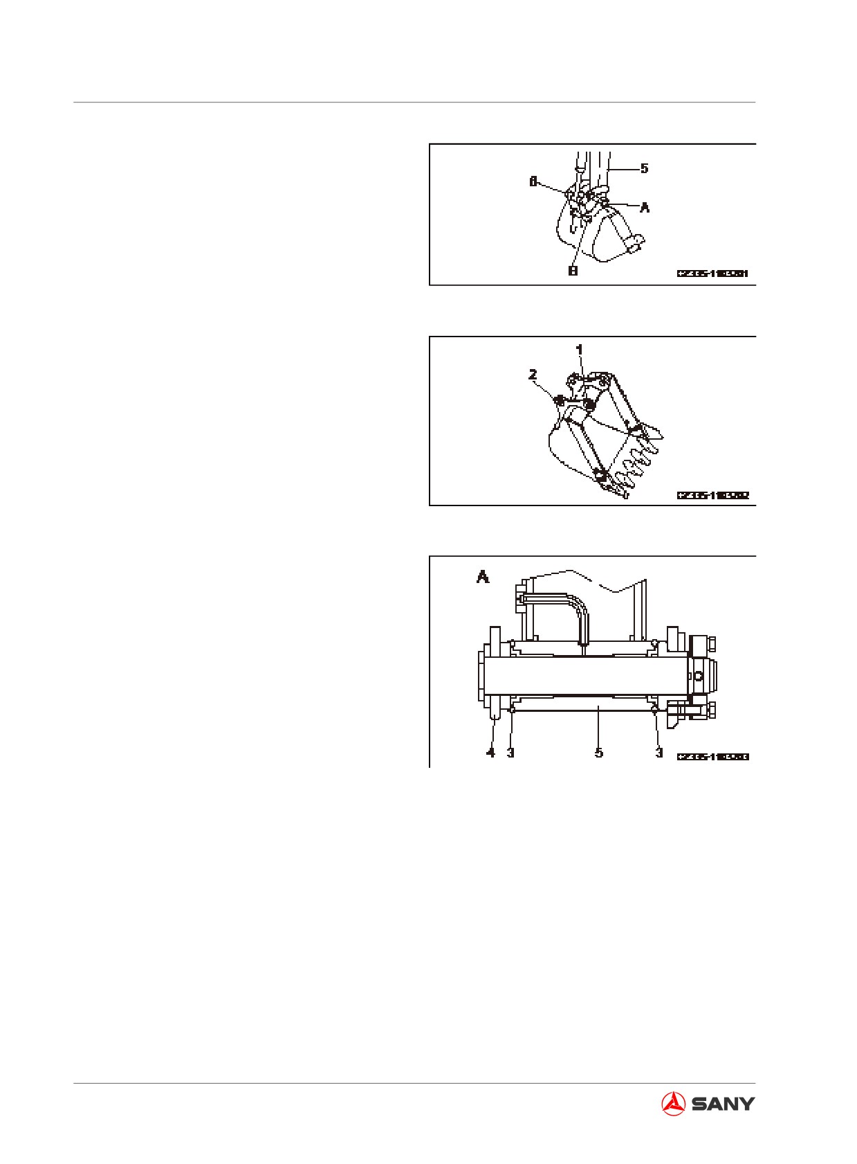
1. Place the bucket on a level ground.
Remark:
Before removing the pin roll, slowly lower the
bucket to a level where it just contacts the
ground.
Fig.
5-37
If a larger force is used to lower the bucket to
the ground, resistance could increase on the
pin roll, causing difficulties while removing it.
Note:
Make sure the pin roll is free from mud or sand
after removal.
Both ends of the bushing are installed with
seals against dust. Be careful not to damage
Fig.
5-38
them.
2. Remove the nuts and screws on the plate
retaining arm pin (A) and link pin (B), take
out arm pin (A) and link pin (B), and then
remove the bucket.
3. Align arm (5) with the bore for bucket
replacement and the link (6) with bore (2).
Insert the greased pin rolls (A) and (B) into
bore (1) and bore (2) respectively.
Fig.
5-39
5-48
Maintenance
Remark:
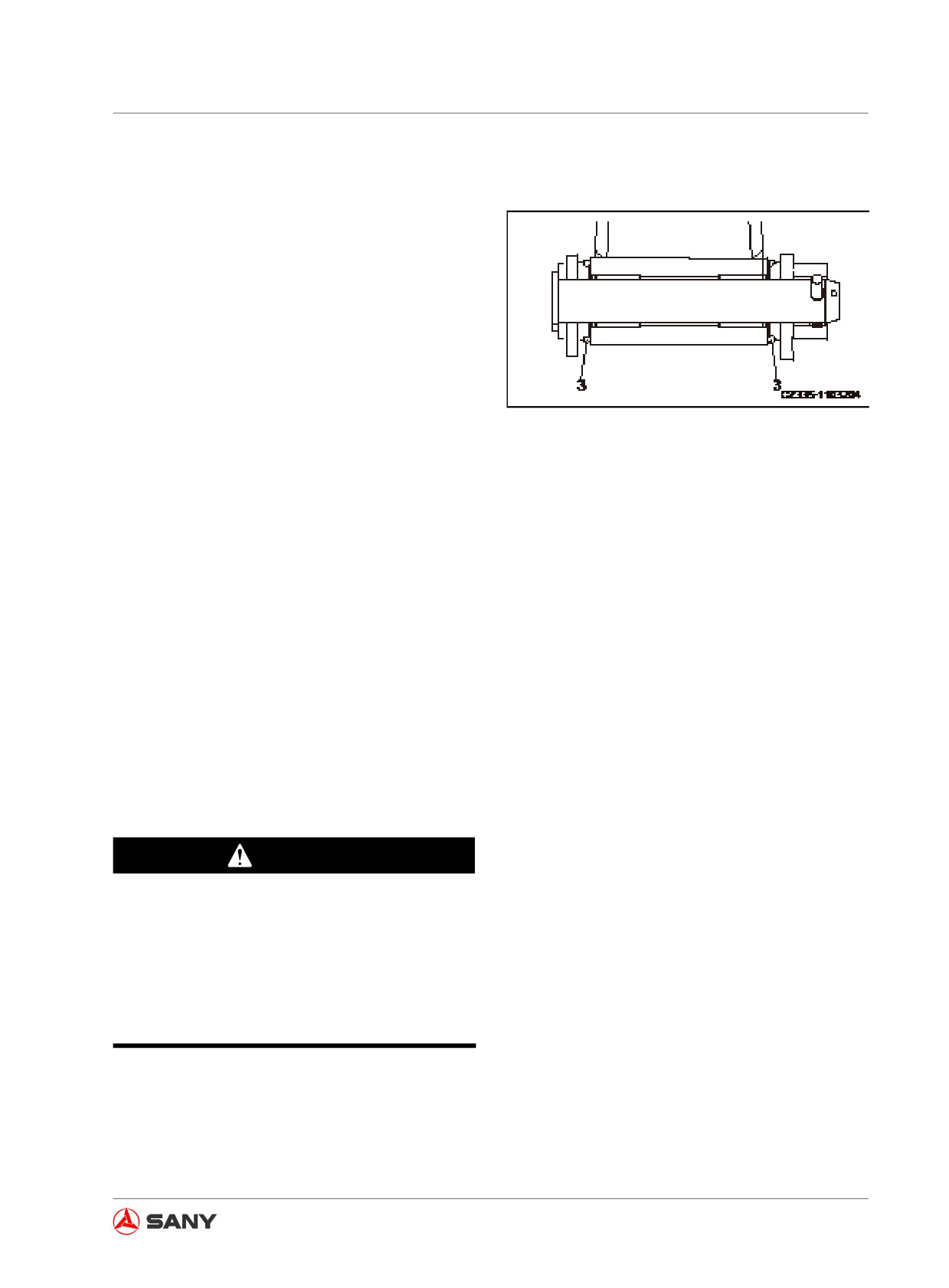
When mounting the bucket, place the O-ring
(3) of bucket (4) to the position, as shown in
the right illustration, corresponding to the arm
pin (A). After the pin roll is inserted, align it to
the standard notch.
4. Reinstall the nuts and bolts onto the plate
retaining the pin rolls. Add grease to the
pin rolls.
Fig. 5-40
Remark:
● Inject sufficient amount of grease till the
grease is squeezed out of the end face.
● Replace any broken seals when replacing
a bucket. The use of broken seals could
allow sand or dust to penetrate through to
the pin roll and cause its abnormal wear.
5.8.2.7 Bucket clearance - adjust
The bucket linking clearance must be readjust-
ed after your machine has been operated for
a period of time. When the linking clearance
is excessively large or small, it is necessary to
install or remove the spacer.
WARNING
Place the work equipment firmly before ad-
justing bucket clearance. Stop the engine
and engage the hydraulic lockout control.
If the hydraulic lockout control is free,
unexpected movement of the work equip-
ment could cause severe accident.
5-49
Maintenance
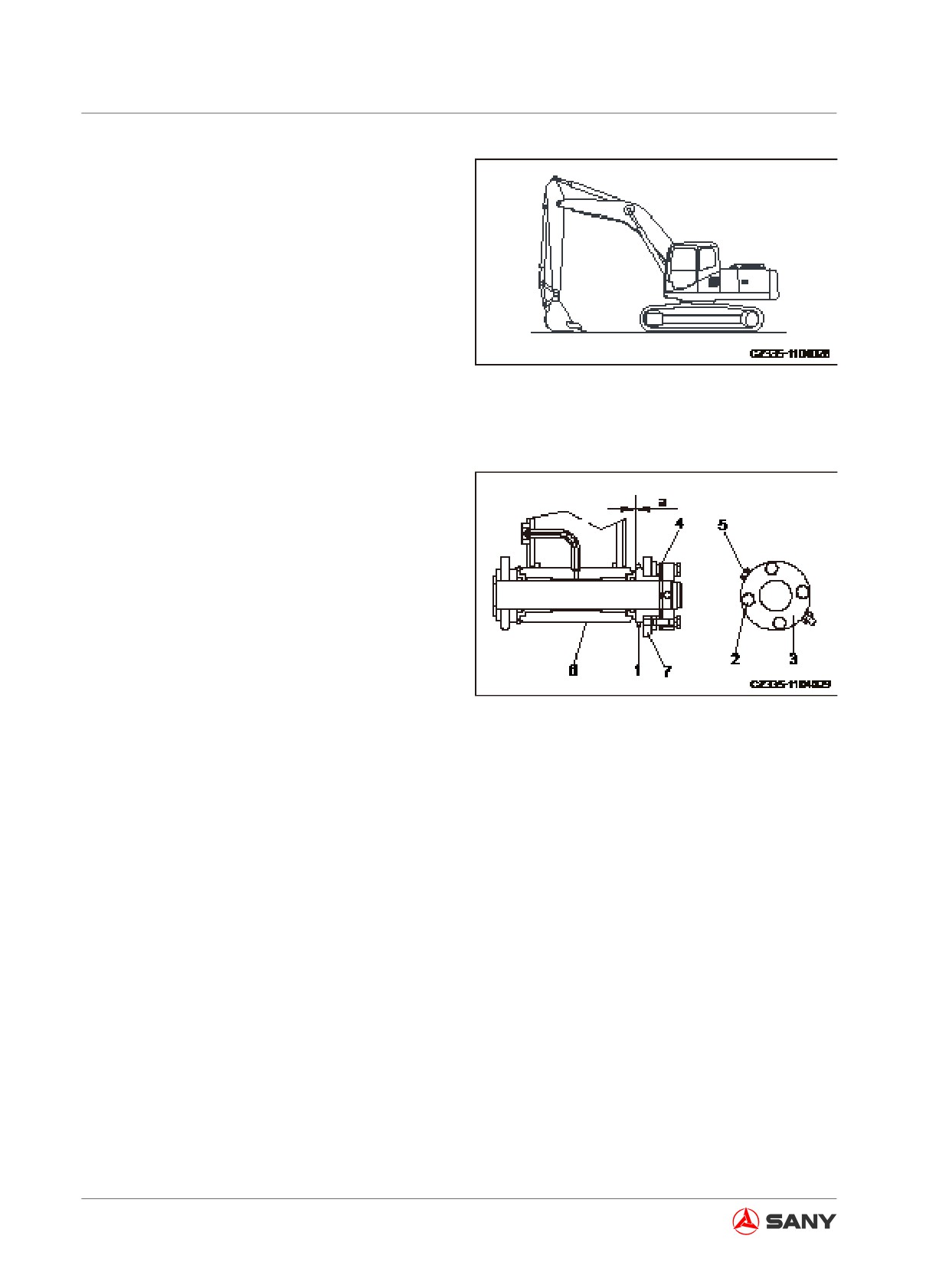
1.
Park your machine on a level ground.
Lower the bucket to the ground, in an at-
titude shown in the right illustration.
2.
Run the engine at low speed. Fix the
bucket on the ground. Slowly turn the
upper structure counterclockwise till the
inside of the left side of the bucket contact
closely with the left end surface of the arm.
3.
Shut off the engine. Lock out and tag out
Fig.
5-41
your machine before proceeding. See
“Lock-out tag-out” on page 2-60.
4.
Move the O-ring (1) and measure the
clearance (a). It is easy to obtain accurate
result with a feeler gauge.
5.
Loosen the four plate-mounting bolts (2) in
order to detach the plate (3). The spacer
has an opening, so it is unnecessary to
remove the bolt when making adjustment.
6.
Remove the spacer equivalent to the
measured clearance (a).
Fig.
5-42
(For example)
If the clearance is 3 mm (0.118 in), remove
two 1.0 mm (0.039 in) spacers and one 0.5
mm (0.02 in) spacer, or one 2.0 mm (0.078
in) spacer and one 0.5 mm (0.02 in) spac-
er. The clearance is reduced to 0.5 mm
(0.02 in). The spacers (4) include three
types, 2.0 mm (0.078 in), 1.0 mm (0.039 in)
and 0.5 mm (0.02 in). When the clearance
(a) is less than one spacer, no adjustment
shall be made.
7.
Tighten the four bolts (2).
If it is difficult to tighten the bolts (2), re-
move the pin-retaining bolt (5) before tight-
ening the bolts (2).
5-50
Maintenance
5.8.2.8 Window washer fluid - check/refill
Always prepare your machine as required
and lock/tag it out before proceeding. See
“Preparing the machine” on page 2-58 and
“Lock-out and tag-out” on page 2-60.
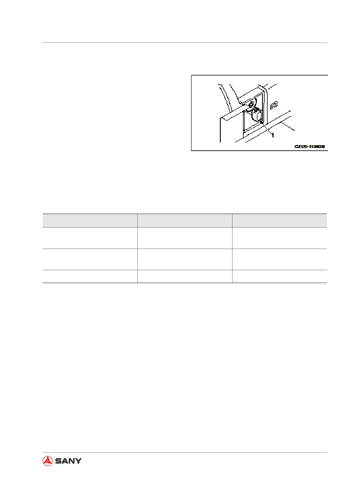
If the washer fluid contains air, check the fluid
level in the reservoir (1). Add washer fluid if
necessary.
To prevent dirt from entering the reservoir, be
Fig. 5-43
careful when filling the washer fluid.
Select a mixture ratio according to ambient
temperature. Therefore, the detergent is to be
diluted with water according the ratios listed
below.
Operating Regions
Mixture Ratio
Anti-Freezing Temperature
Detergent 1/3:
General
- 10℃ (14ºF)
Water 2/3
Detergent 1/2:
Cold regions in winter
- 20℃ (- 4ºF)
Water 1/2
Frigid regions in winter
Pure detergent
- 30℃ (- 22ºF)
Table 5-10
There are two types of detergent: one for
-10℃ (4°F) (common) and one for -30℃ (-22ºF) (frigid
regions), which can be selected according to the operating region.
5-51
Maintenance
5.8.2.9 Air conditioner - inspect/service
Always prepare your machine as required
and lock/tag it out before proceeding. See
“Preparing the machine” on page 2-58 and
“Lock-out and tag-out” on page 2-60.
Checking refrigerant (gas) level
WARNING
● The refrigerant getting into your eyes
or on your skin can cause blindness
or freezing injury. Never touch the re-
frigerant. Never loosen any parts of the
refrigerant lines.
● Keep any naked fire away from the
leaking position of refrigerant gas.
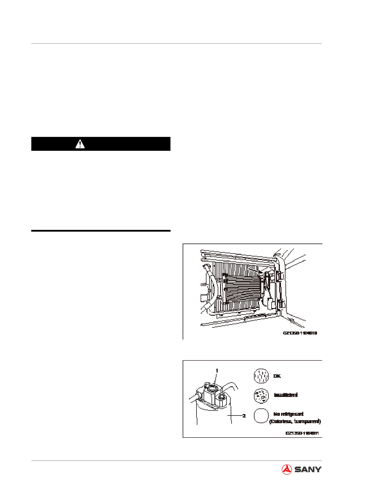
Insufficient refrigerant (R134a) will severely
impair the cooling performance.
When the engine is running at high speed, op-
erate the air conditioner for strong refrigeration
and observe through the sight glass (1) on the
condenser reservoir (2) in order to inspect the
condition of refrigerant gas flowing to the tube.
● The refrigerant flows without bubble: per-
fect
● The refrigerant flow contains bubbles that
Fig. 5-44
pass continuously: refrigerant level low
● Colorless and transparent: no refrigerant
Remark:
The appearance of bubbles indicates low re-
frigerant level. Please consult Sany distributor
to add refrigerant. Running the air conditioner
with low refrigerant level could damage its
compressor.
Inspection during idle period
Fig. 5-45
5-52
Maintenance
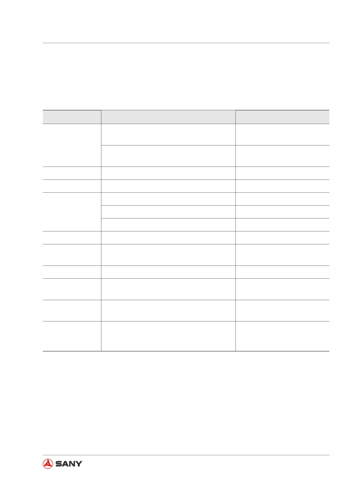
When the air conditioner will not be used for a long period of time, the air conditioner
shall be operated for 3-4 minutes each month in order to lubricate the compressor com-
ponents.
Components
Description
Service Interval
Twice a year (spring and au-
Refilling
tumn)
Refrigerant (gas)
Tube connections and internal leakage of parts
Daily
and components
Condenser
Radiator fins plugged
Every 500 hours
Compressor
Function
Every 4000 hours
Loose and bent
Every 250 hours
V-belt
Deterioration, wear, scratch and cracking
Every 250 hours
Noise, odor smell or abnormal heat
When required
Fan motor and fan
Function (check for abnormal noise)
When required
Air conditioner air
Air flow control switch and switching function
Daily
flow switch
Control unit
Function (make sure the function is normal)
When required
Loose connections and loose or detached nuts
Joining bolts
Every 6 months
and bolts
Installation condition, loose connections, air
Connection tubes
When required
leakage or any damage
Reservoir dryer
Temperature difference indicates a blocked
temperature differ-
Every year
dryer.
ence
Table 5-11
5-53
Maintenance
5.8.2.10 Gas spring - inspect
WARNING
The Gas Spring contains high-pressurized
nitrogen. Wrong operation can cause ex-
plosion and result in machine damage and
personal injury or death. The following
items shall be observed when dealing with
the Gas Spring.
● Be away from naked fire.
● Never drill or weld the Gas Spring.
● Never hammer the Gas Spring or ex-
pose it under any impact.
Always prepare your machine as required
and lock/tag it out before proceeding. See
“Preparing the machine” on page 2-58 and
“Lock-out and tag-out” on page 2-60.
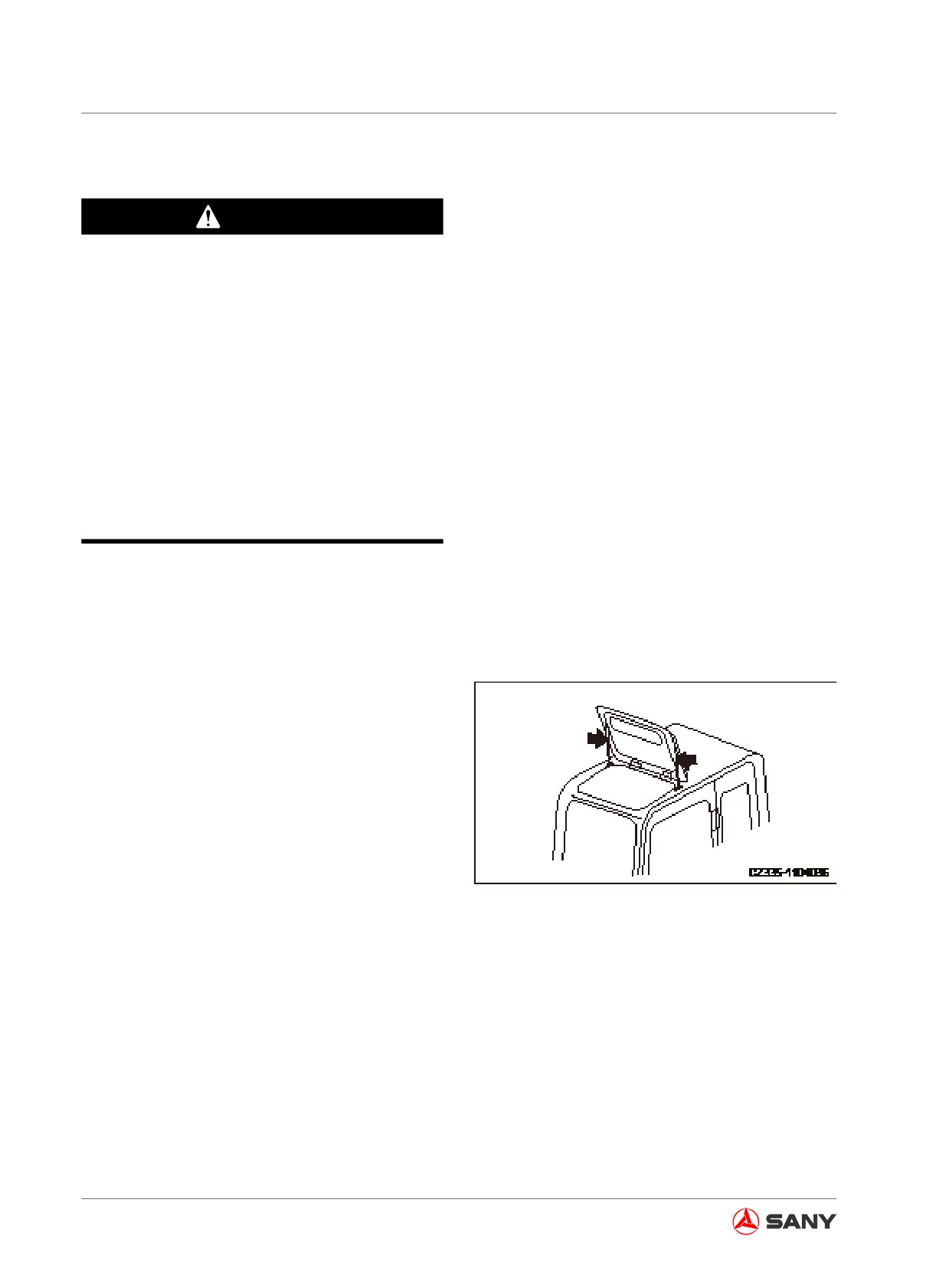
The air springs are located on top of the cab (at
both the left and right sides).
Contact your Sany distributor for inspection,
repair and replacement in case of the following
conditions.
● The cab roof hatch cannot be opened eas-
ily.
● The cab roof hatch cannot be kept open.
Fig. 5-46
● Oil or air leaks from the air spring.
5-54
Maintenance
5.8.2.11 Air in hydraulic system - purge
Always prepare your machine as required
and lock/tag it out before proceeding. See
“Preparing the machine” on page 2-58 and
“Lock-out and tag-out” on page 2-60.
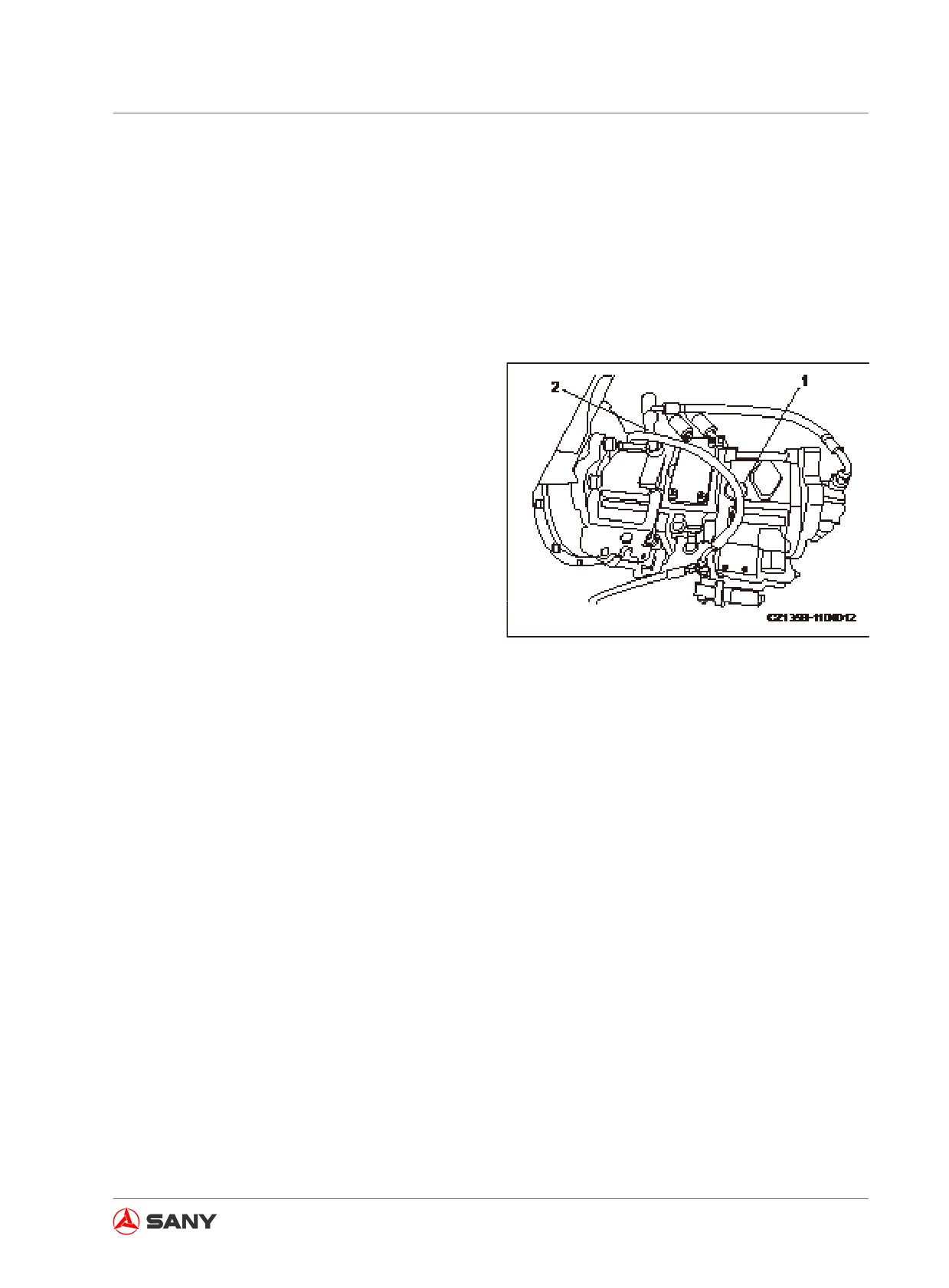
1. Purging air from the pump
1) Loosen air vent plug (1) and check for
oil leak.
2) If no oil leaks, disconnect drain hose
from hydraulic pump and add hydraulic
oil to hydraulic pump through drain port
(2).
Well secure the disconnected hose. To
prevent overflow, hose opening must be
higher than oil level in hydraulic tank.
3) Tighten the plug (1) and reconnect the
drain hose after purging the air.
Fig.
5-47
Note:
If drain hose is reconnected before tightening
the plug (1), oil will squirt out of the plug (1).
If the pump is operated when it is not fully filled
with hydraulic oil, extra heat will be generated
and pump damage could result.
2. Starting the engine
See “Engine Starting” on page 4-22.
After starting the engine run it at low speed
for 10 minutes before you perform any op-
eration.
3. Purging air from hydraulic cylinders
1) Run the engine at low idle speed.
Extend and retract oil cylinder 4-5 times.
Note that the piston shall not reach its
5-55
Maintenance
stroke end. Keep it 100 mm (3.9 in)
from stroke end.
2) Operate each cylinder 3-4 times to its
stroke end.
3) Operate each cylinder 4-5 times to its
stroke end in order to purge air com-
pletely.
Note:
If you instantly run the engine at high speed or
operate a cylinder to its stroke end, air in cylin-
der could damage piston seal.
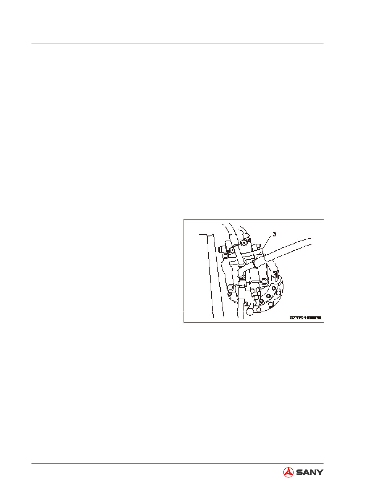
4. Purging air from swing motor
1) Run the engine at low speed. Loosen
the hose (3) at the port S. Check if oil
comes out of the hose (3) from the port
S.
Note:
Do not operate the swing drive under any cir-
cumstances.
2) If no oil is seen, shut off the engine.
Remove the hose (3) from the port S
and add hydraulic oil to the motor shell.
Fig.
5-48
3) Tighten the hose (3) at the port S after
purging the air from the swing motor.
4) With the engine running at low idle
speed, swing evenly and slowly to the
left side and the right side at least two
times. The air will be expelled from the
swing drive oil path.
Note:
● The air in the swing motor could damage
the motor bearing.
● To replace the relief valve of the travel mo-
5-56
Maintenance
tor, consult Sany distributor for replace-
ment and air elimination.
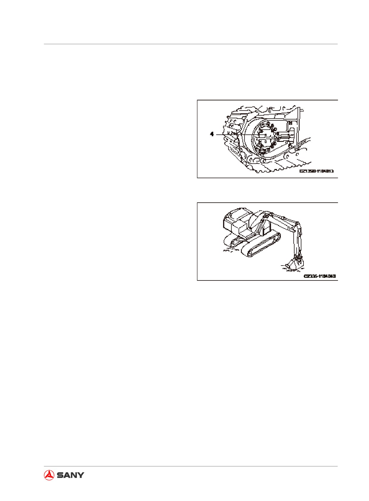
5. Eliminate air from the travel motor (only
when the oil has been discharged from the
travel motor shell)
1) Run the engine at low speed. Loosen
the air vent screw plug (4). Tighten the
screw plug if oil is seen.
2) Run the engine at low speed. Swing the
work equipment 90 degrees in order to
place it at the track side.
3) Raise the machine with the force of the
Fig. 5-49
work equipment. With the track lifted
just above the ground, run the track
unloaded for two minutes. Repeat this
operation for both tracks and run the
tracks back and forth uniformly.
6. Eliminate air from attachment (if equipped)
If a breaking hammer or other attachment
has been installed, run the engine at low
idle speed and operate the attachment
control pedal repeatedly (about 10 times)
Fig.
5-50
till the air is expelled from the oil path com-
pletely.
Note:
● If manufacturer of the attachment has pro-
vided instruction on eliminating air from
the attachment, the instruction shall be fol-
lowed to eliminate the air.
● Turn off the engine after air elimination.
Wait five minutes before operation in order
to eliminate the bubbles in hydraulic cylin-
der.
● Check for oil leakage and wipe off the oil
overflowed.
● Check the oil level after purging the air.
Add oil if the oil level is low.
5-57
Maintenance
5.8.2.12 Hydraulic circuit internal pressure - release
WARNING
● The hydraulic circuit is always under
pressure. In this case, the pressure in
hydraulic circuit is to be released when
checking or replacing the hoses or fit-
tings. Without doing so, the pressur-
ized oil will squirt out and cause seri-
ous personal injury.
● After the engine is stopped, the com-
ponents and oil are still hot and can
cause serious burn. Wait until the tem-
perature comes down before operating.
● The oil may squirt out when remov-
ing the oil filler cap. Therefore, slowly
remove the cap in order to release the
internal pressure.
1. Park your machine on a hard, level ground.
2. Within 15 minutes since the engine is shut
off, turn the start switch to ON position and
cycle the work equipment control lever and
the travel control lever in all directions in
order to release the internal pressure.
3. Lock/tag it out before proceeding. See
“Lock-out tag-out” on page 2-60.
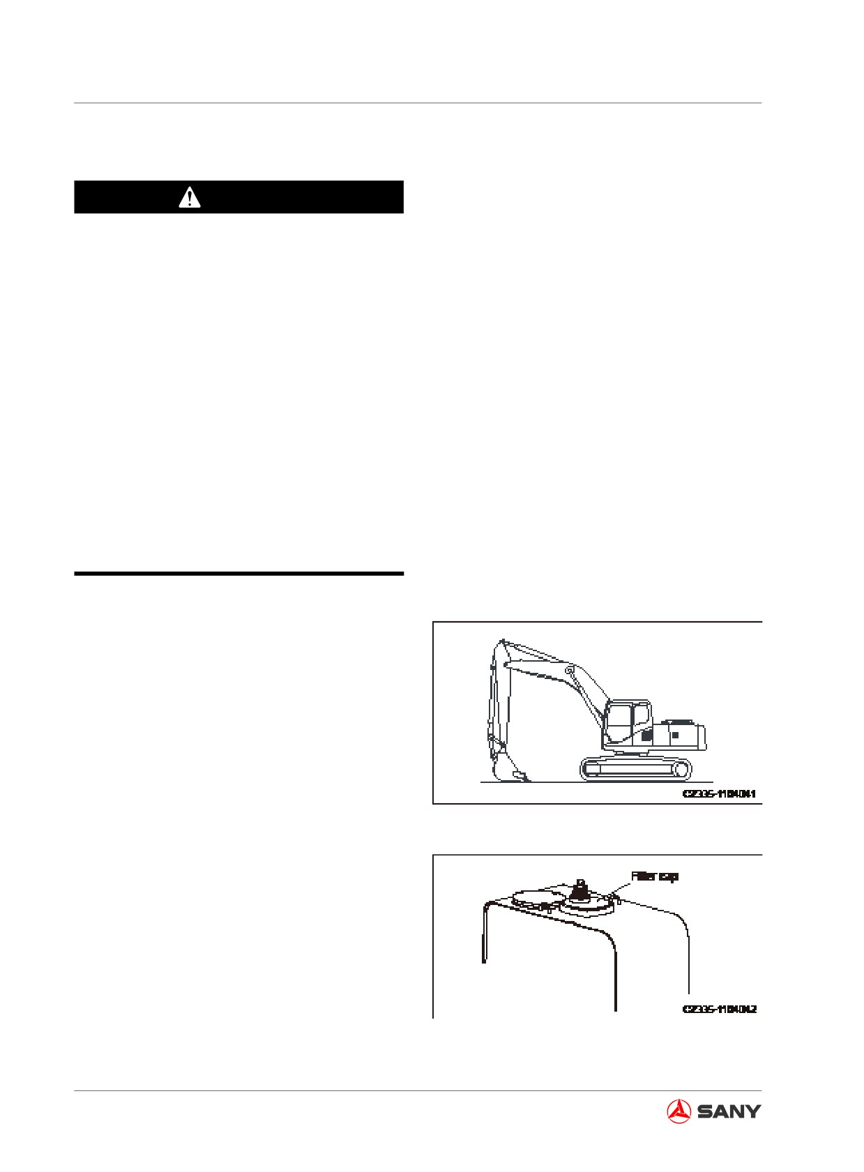
Fig. 5-51
4. Slowly loosen the oil filler cap on top of
the hydraulic tank in order to release the
internal pressure.
Fig. 5-52
5-58
Maintenance
5.8.3 Checks before starting
For more information about the following items
see “Checks before starting” on page 4-7.
● Drain water and sediment from fuel tank.
● Check water separator and drain water
and sediment.
● Check oil level in hydraulic tank and refill
the tank.
● Check coolant level and add coolant.
● Check oil level in engine oil pan and add
oil.
● Check electric wires.
● Check fuel level and refuel the tank.
● Check work lamp switch.
● Check the function of horn.
● Check engine lower exhaust pipe and keep
it clean. (Check exhaust pipe at any time in
earthwork.)
5-59
Maintenance
5.8.4 Every 100 service hours
5.8.4.1 Lubrication
NOTICE
● If the lubricated components produce abnormal noise, additional lubrication is re-
quired besides regular maintenance.
● A new machine shall be greased every 10 hours within the initial 50 hours.
● After operating in water, the machine's wet pin rolls are to be greased.
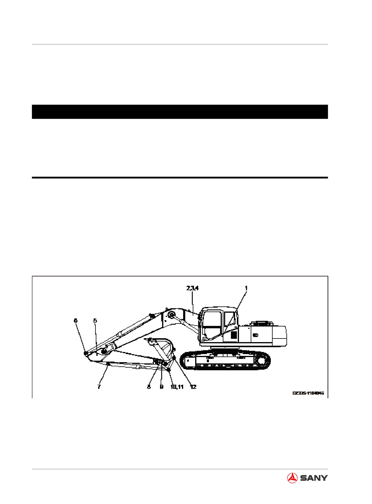
1. Adjust your machine to a to-be-greased attitude shown in the illustration below, lower the work
equipment to the ground and then turn off the engine.
2. Lock/tag it out before proceeding. See “Lock-out tag-out” on page 2-60.
3. Use a grease gun to inject grease through the greasing points indicated in Fig. 5-53.
4. Finally, wipe off the used grease that has been squeezed out.
Fig. 5-53
5-60
Maintenance
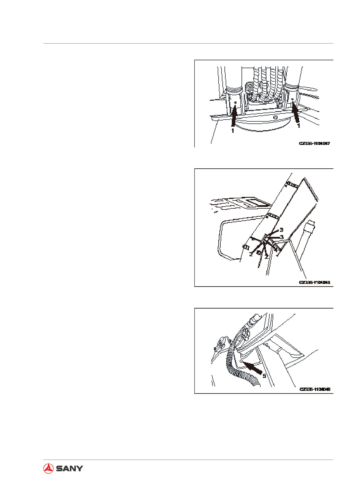
(1) Boom cylinder root pin (2)
Fig. 5-54
(2) Boom root pin (2)
(3) Boom cylinder piston rod end (2)
(4) Arm cylinder root pin (1)
Fig. 5-55
(5) Boom-arm joining pin (2)
Fig. 5-56
5-61
Maintenance
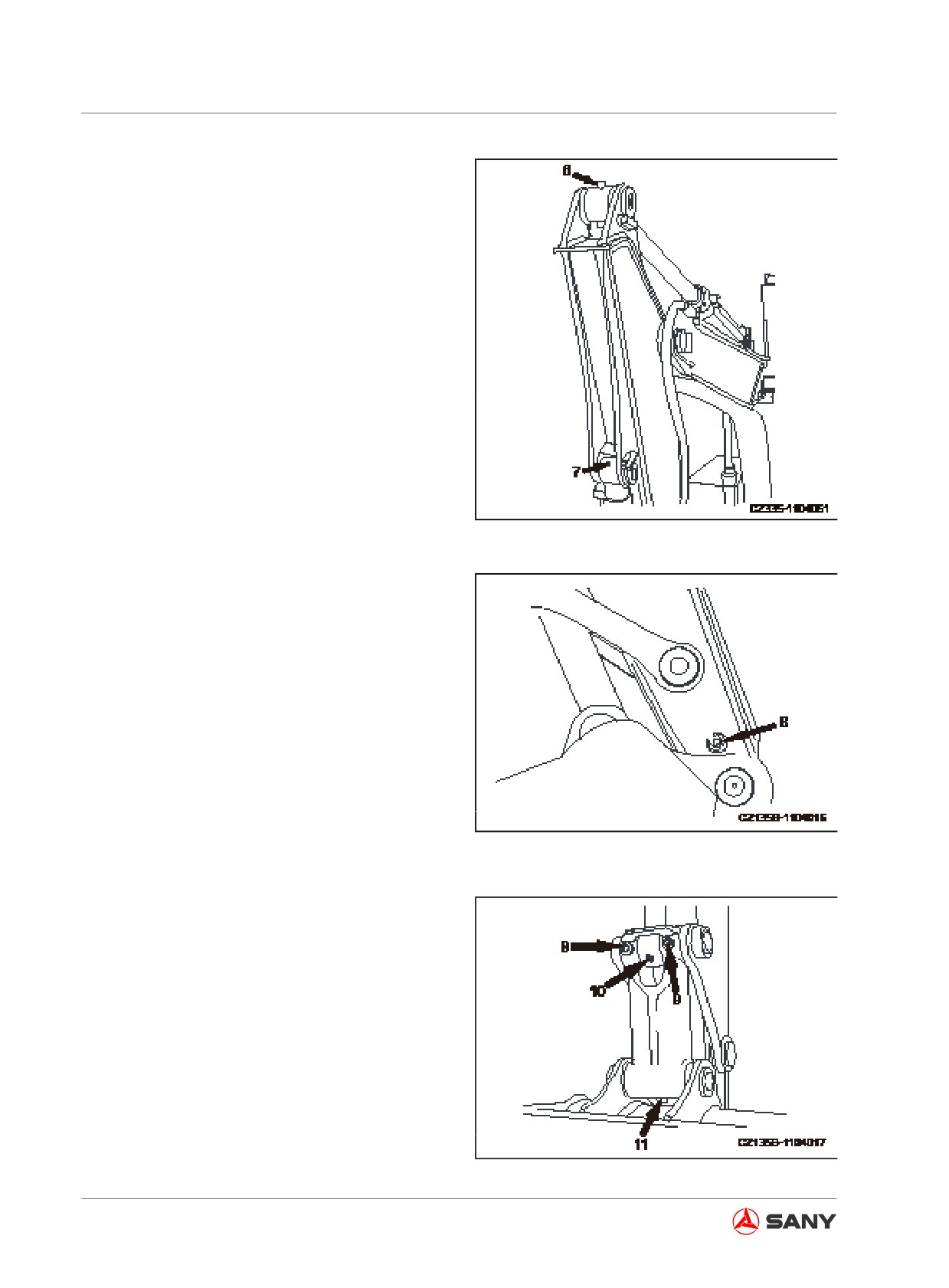
(6) Arm cylinder piston rod end (1)
(7) Bucket cylinder root pin (1)
Fig. 5-57
(8) Arm-Bucket joining pin (1)
Fig. 5-58
(9) Rod joining pin (2)
(10) Bucket cylinder piston rod end (1)
(11) Bucket-rod joining pin (1)
Fig. 5-59
5-62
Maintenance
5.8.5 Every 250 service hours
5.8.5.1 Compressor belt tension - inspect/
adjust
Always prepare your machine as required
and lock/tag it out before proceeding. See
“Preparing the machine” on page 2-58 and
“Lock-out and tag-out” on page 2-60.
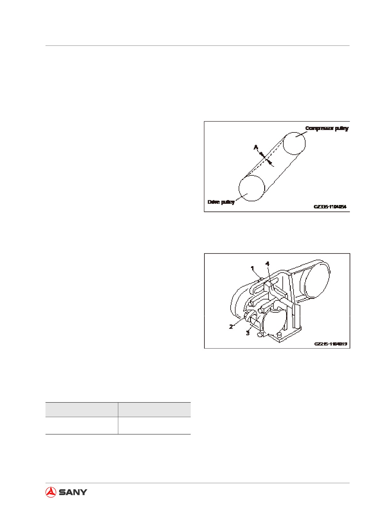
Inspection
With a force of about 58.8N (6kgf), press with
your finger the middle section of the belt be-
tween the drive pulley (1) and the compressor
pulley (2) in order to check the deflection (A),
which should be 5-8mm (0.20in-0.31in).
Fig.
5-60
Adjustment
1. Loosen the bolts (1) and (2).
2. Move the compressor (3) and its bracket (4)
in order to adjust belt tension.
3. Tighten the bolt (1) and (2) after positioning
the compressor (3).
4. Check again the belt tensioning device
after adjustment.
Fig.
5-61
Reference
Use a tension meter to check the belt tension
of the compressor.
New Belt
Used Belt
637±108 (N)
441±88.2 (N)
(65±11 (kgf))
(45±9 (kgf))
Table 5-12
5-63
Maintenance
Note:
● Check for damaged pulleys and worn V-
groove and V-belt. In addition, make sure
that the V-belt must not rub against the
bottom of the V-groove.
● Consult Sany distributor to replace the belt
timely in case of the following conditions.
● The fan belt has been stretched and
little margin is left for adjustment.
● Cuts or cracks are found in the belt.
● The belt skids or squeaks.
● A newly installed V-belt shall be readjusted
after one hour operation.
5-64
Maintenance
5.8.5.2 Oil in engine oil pan and oil filter -
change/replace
WARNING
When the engine has just been stopped,
the parts and oil are still hot and can
cause serious burn. Wait until they are
cool enough before doing the job.
Always prepare your machine as required
and lock/tag it out before proceeding. See
“Preparing the machine” on page 2-58 and
“Lock-out and tag-out” on page 2-60.
Prepare as the following:
Fig.
5-62
● Capacity of engine oil pan: See “Fluid
capacities” on page 5-19.
● Filter wrench
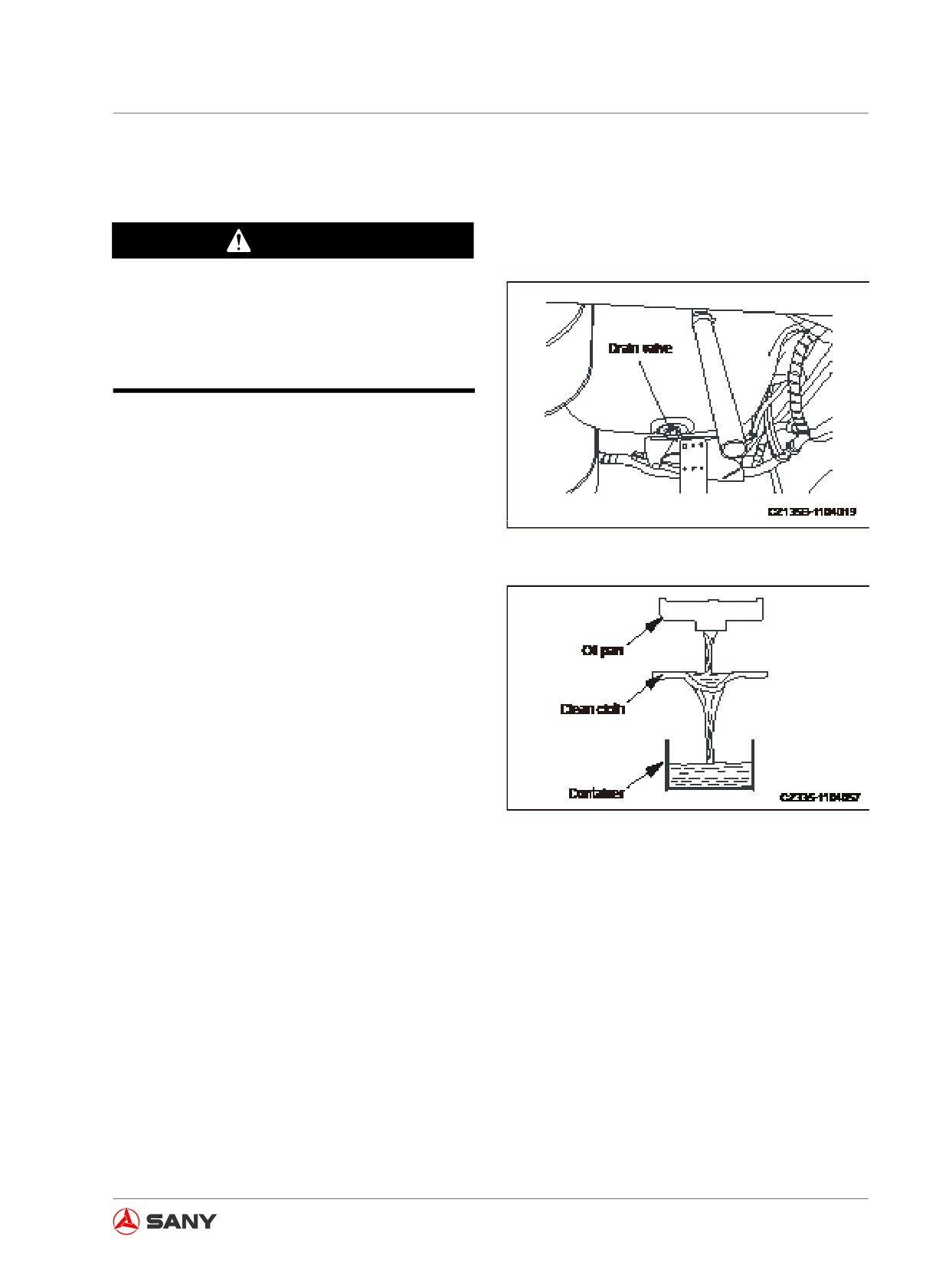
1. Remove the bottom cover of the machine.
Place a container under the drain valve.
(Choose a container of a proper size ac-
cording to the capacity table). The oil will
be drained into the container through a
piece of clean cloth.
Fig.
5-63
2. To avoid splashing of the oil, slowly open
the drain valve to discharge oil, and close
the valve after drainage.
5-65
Maintenance
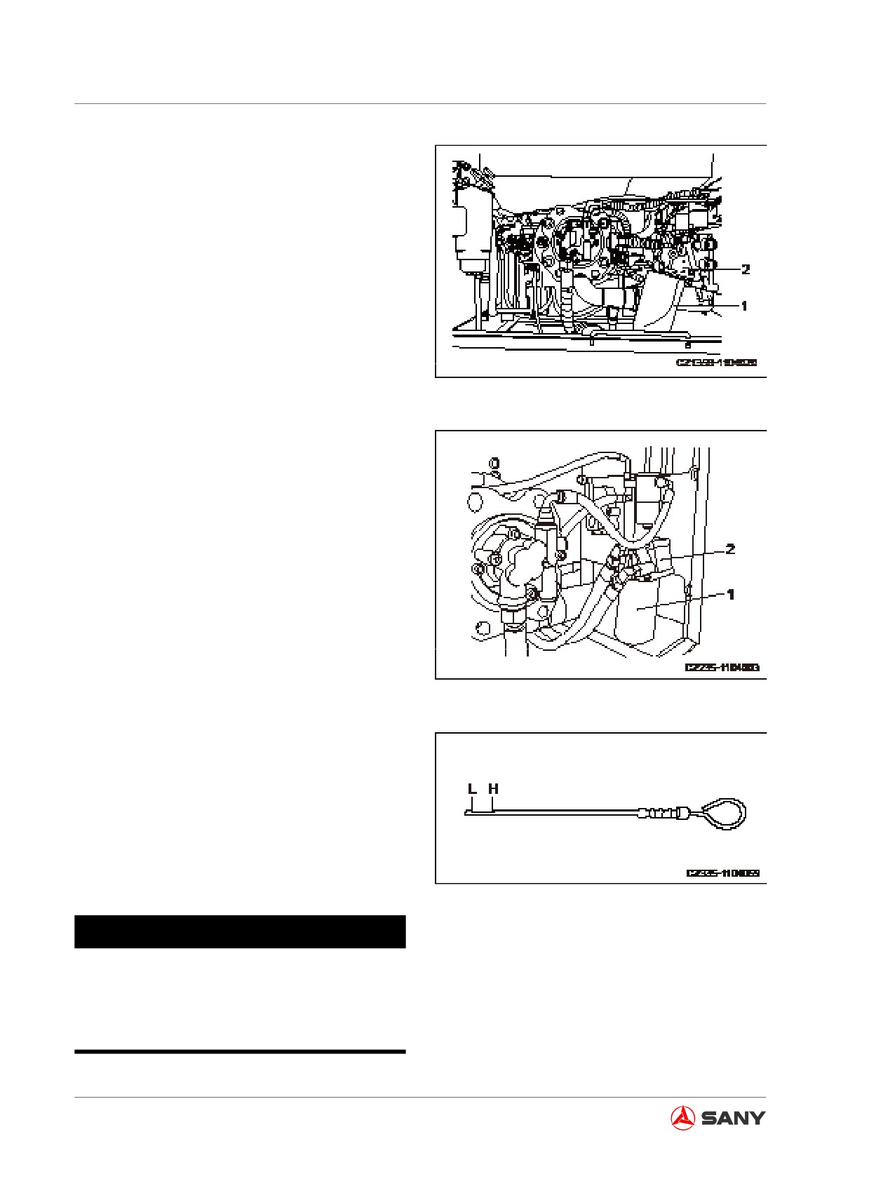
3. Open the right door and turn the filter
(1) leftward with filter spanner in order to
disassemble the filter.
4. Clean the filter seat (2). Fill the new filter
with clean engine oil. Apply engine oil (or a
film of grease) to the filter sealing surface
and the threads before installing the filter
to its seat.
Fig. 5-64
Remark:
Check the filter seat (2) for presence of used
seal. The presence of used seal in the filter
seat (2) can cause oil leakage.
5. The installation requires contact of the
sealing surface with that of the filter seat
(2). Turn the filter 3/4-1 turn.
6. After replacement of the filter, open the
engine's hood and fill engine oil through
the filler to a level between the H and L
marks of the dipstick.
Fig. 5-65
7. Run the engine idly for a short time and
then turn off the engine. Check again the
oil level, which shall be between the H and
L marks of the dipstick. For more informa-
tion see “Oil in engine oil pan and oil
filter - change/replace” on page 5-65.
8. Reinstall the bottom cover.
Fig. 5-66
NOTICE
Contact your Sany distributor to obtain
genuine engine oil in order to guarantee
oil quality and ensure 250 service hours.
5-66
Maintenance
5.8.5.3 Primary fuel filter - replace
WARNING
● Never replace the filter immediately af-
ter the engine is shut down, as all parts
are still hot. Wait for the parts to cool
enough before replacement.
● High pressure is created in the fuel
system when the engine is running.
● Before replacing the filter, wait at least
30 seconds since engine stoppage. The
replacement work shall be carried out
after the internal pressure drops to a
safe level.
● Be away from fire sources.
Note:
● Sany genuine fuel filter is a special filter
of effective filtration. The filter must be re-
placed with a genuine one.
The use of other parts may allow dirt or de-
bris to get into the fuel system and cause
the injection system failure. Therefore,
avoid using any substitutes.
● It is more important to prevent dirt from
getting into the fuel system during inspec-
tion and service. In case of any parts con-
taminated by dust, flush them clean with
diesel fuel.
● Prepare a container to hold the fuel
drained.
● Prepare a filter wrench.
5-67
Maintenance
Always prepare your machine as required
and lock/tag it out before proceeding. See
“Preparing the machine” on page 2-58 and
“Lock-out and tag-out” on page 2-60.
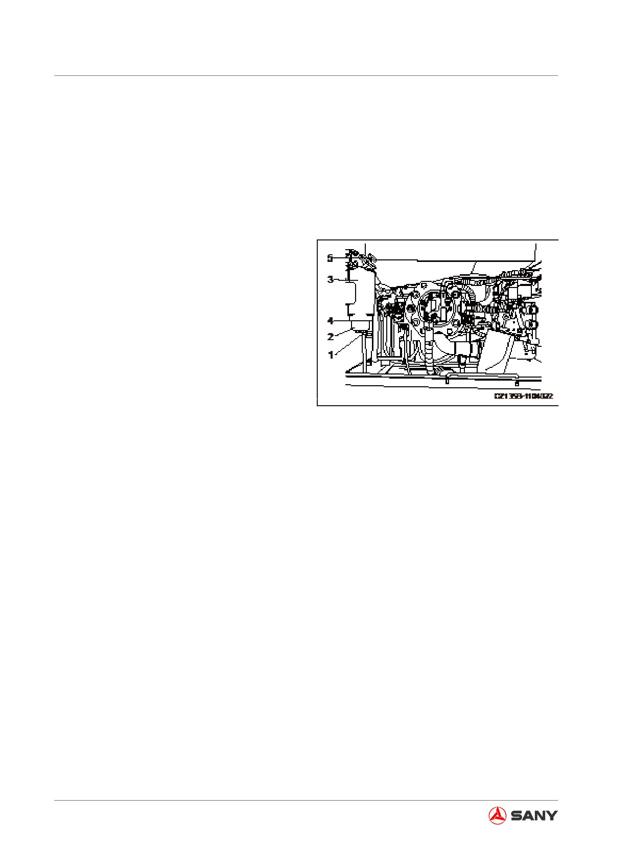
1.
Open the door on the right side of machine.
2.
Place a fuel container under the filter.
3.
Loosen the drain valve (1) to discharge
water and sediment in the bowl (2). Also
drain the fuel in filter (3).
4.
Use a filter wrench to turn counterclock-
wise the bowl (2) in order to remove it. (The
bowl can be reused.)
5.
Use the filter wrench to turn counterclock-
wise the filter (3) in order to remove it.
6.
Install the bowl (2) to the bottom of new
filter. Always replace the O-ring seal (4).
Fig. 5-67
7.
Apply oil to seal surface during installa-
tion. Make the seal and filter have a close
contact before further tightening the filter
by 1/4 - 1/2 turn.
If the bowl (2) was over-tightened, the
O-ring seal might be damaged and fuel
leak could result. If the bowl (2) was not
tightened enough, fuel will leak through
the gap with O-ring seal. To prevent such
problems, always tighten it to the specified
torque.
8.
Clean the filter seat. Add clean fuel to new
filter. Apply a thin layer of oil to the seal
surface and install the filter to the filter
seat.
5-68
Maintenance
Note:
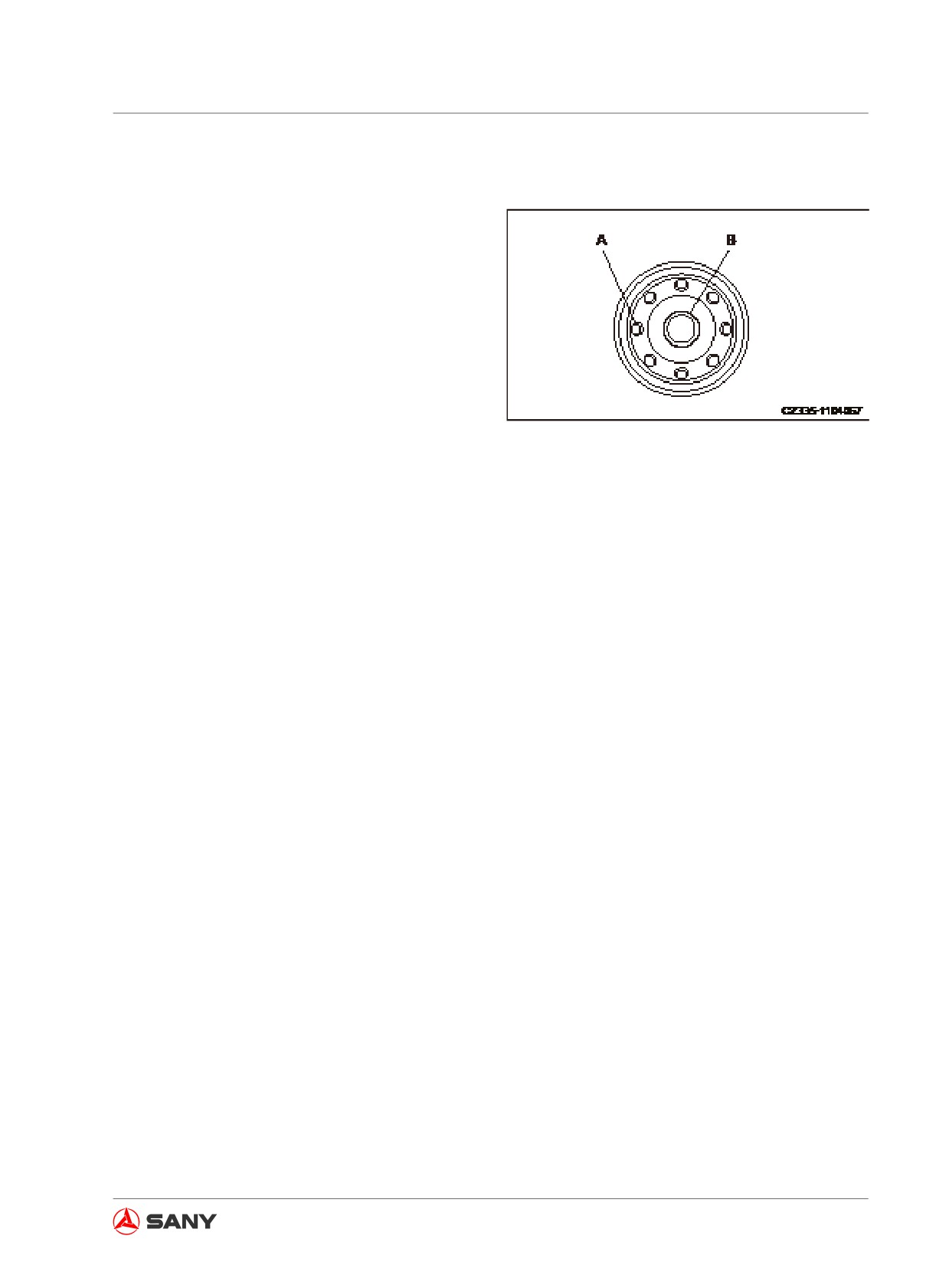
● Never remove the cover (B) while filling the
fuel. Always fill fuel via the eight(8) external
holes (A).
● Remove the cover (B) after filling. Install
the fuel filter.
● Always fill clean fuel. Take care to keep
the fuel free from dust or dirt. Be especially
careful that the central part is clean and
never remove the cover (B) during filling.
Always keep the central part free from con-
Fig. 5-68
tamination.
9. Tighten the filter until the seal contacts
the filter seat. Further turn it by 3/4 turn.
If the filter cartridge was over-tightened,
the seal might be damaged and fuel leak
could result. If the filter cartridge was not
tightened enough, fuel will leak through
the gap with seal. Always tighten it to the
specified torque.
10. Check drain valve (1) to see if it is tight-
ened properly.
11. Release the air after replacing filter (3).
Air-purging steps:
12. Fill fuel into the fuel tank until the float
reaches the maximum level.
13. Use a transfer pump (5) to pump the fuel in
and out until heavy resistance is felt.
Remark:
● It is unnecessary to remove the plug on the
primary fuel filter and the secondary fuel
filter.
● When fuel exhausts, operate the transfer
pump (5) to purge air.
5-69
Maintenance
14. After purging the air, push in the knob of
pump (5) and tighten it.
15. After replacing the filter, start the engine
and run the engine at low idle for 10 min-
utes.
Check the filter seal and the cover for fuel
leak. Check the tightening degree of the
filter when fuel leak is found.
If fuel leak still exists, repeat step
1
through step 7 to remove the filter. If the
seal is found damaged or cut by foreign
substance, replace filter cartridge. Repeat
step 8 through step 14 to install a new fil-
ter cartridge.
5-70