SANY Crawler Hydraulic Excavator SY115C9, SY135C8, SY135C9, SY155H. Safety, Operation and Manitenance Manual - page 9
Maintenance
Note:
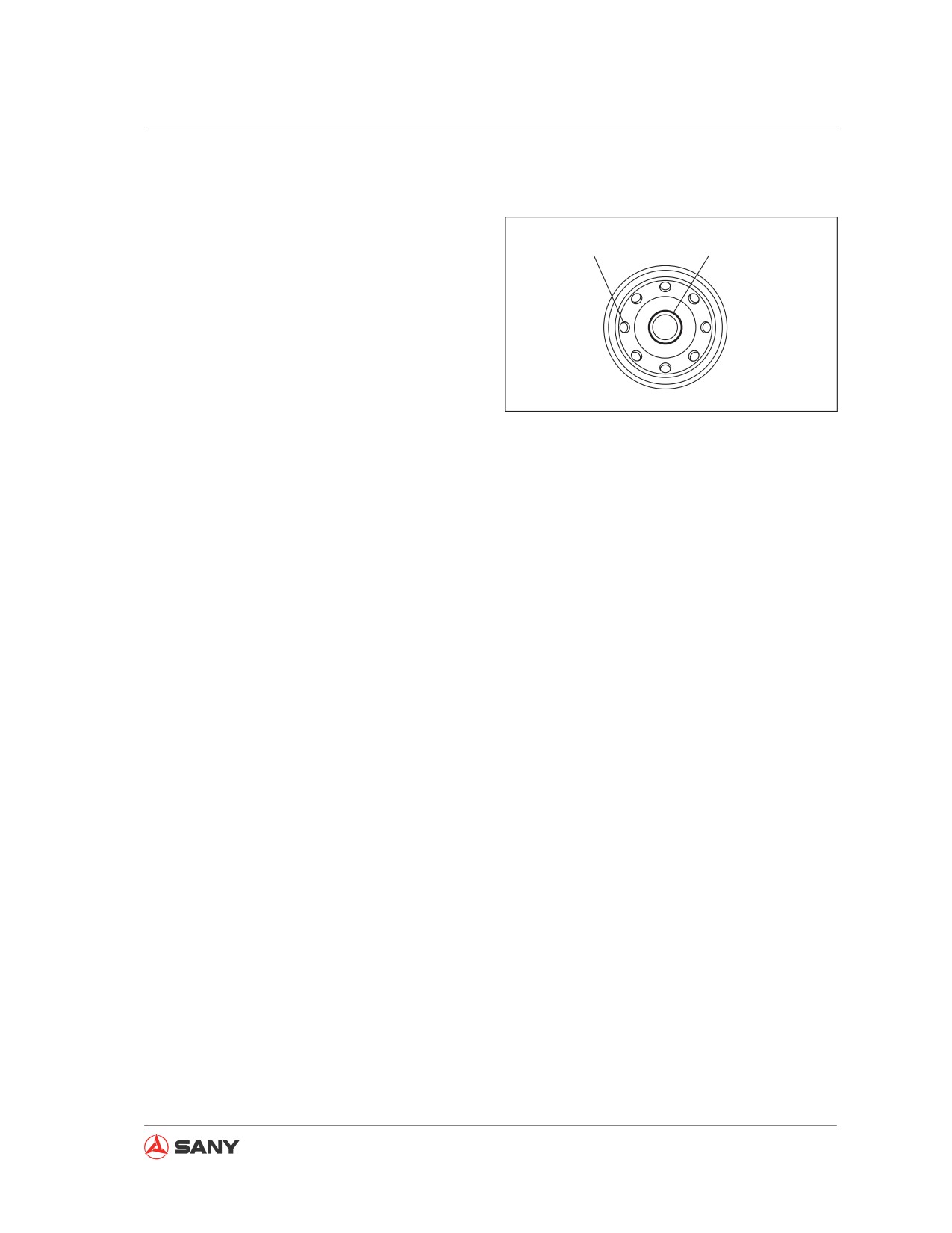
● Never remove the cover (B) while filling the
fuel. Always fill fuel via the eight(8) external
A
B
holes (A).
● Remove the cover (B) after filling. Install
the fuel filter.
● Always fill clean fuel. Take care to keep
the fuel free from dust or dirt. Be especially
careful that the central part is clean and
never remove the cover (B) during filling.
CZ335-1104067
Always keep the central part free from con-
Fig. 5-68
tamination.
9. Tighten the filter until the seal contacts
the filter seat. Further turn it by 3/4 turn.
If the filter cartridge was over-tightened,
the seal might be damaged and fuel leak
could result. If the filter cartridge was not
tightened enough, fuel will leak through
the gap with seal. Always tighten it to the
specified torque.
10. Check drain valve (1) to see if it is tight-
ened properly.
11. Release the air after replacing filter (3).
Air-purging steps:
12. Fill fuel into the fuel tank until the float
reaches the maximum level.
13. Use a transfer pump (5) to pump the fuel in
and out until heavy resistance is felt.
Remark:
● It is unnecessary to remove the plug on the
primary fuel filter and the secondary fuel
filter.
● When fuel exhausts, operate the transfer
pump (5) to purge air.
5-69
Maintenance
14. After purging the air, push in the knob of
pump (5) and tighten it.
15. After replacing the filter, start the engine
and run the engine at low idle for 10 min-
utes.
Check the filter seal and the cover for fuel
leak. Check the tightening degree of the
filter when fuel leak is found.
If fuel leak still exists, repeat step
1
through step 7 to remove the filter. If the
seal is found damaged or cut by foreign
substance, replace filter cartridge. Repeat
step 8 through step 14 to install a new fil-
ter cartridge.
5-70
Maintenance
5.8.5.4 Secondary fuel filter - replace
WARNING
● Never replace the filter immediately af-
ter the engine is shut down, as all parts
are still hot. Wait for the parts to cool
enough before replacement.
● High pressure is created in the fuel
system when the engine is running.
● Before replacing the filter, wait at least
30 seconds since engine stoppage. The
replacement work must be carried out
after the internal pressure drops to a
safe level.
● Be away from fire sources.
Note:
● Sany genuine fuel filter is a special filter
of effective filtration. The filter must be re-
placed with a genuine one.
The use of other parts may allow dirt or de-
bris to get into the fuel system and cause
the injection system failure. Therefore,
avoid using any substitutes.
● It is more important to prevent dirt from
getting into the fuel system during inspec-
tion and service. In case of any parts con-
taminated by dust, flush them clean with
diesel fuel.
● Prepare a container to hold the fuel
drained.
● Prepare a filter wrench.
5-71
Maintenance
Always prepare your machine as required
and lock/tag it out before proceeding. See
“Preparing the machine” on page 2-58 and
“Lock-out and tag-out” on page 2-60.
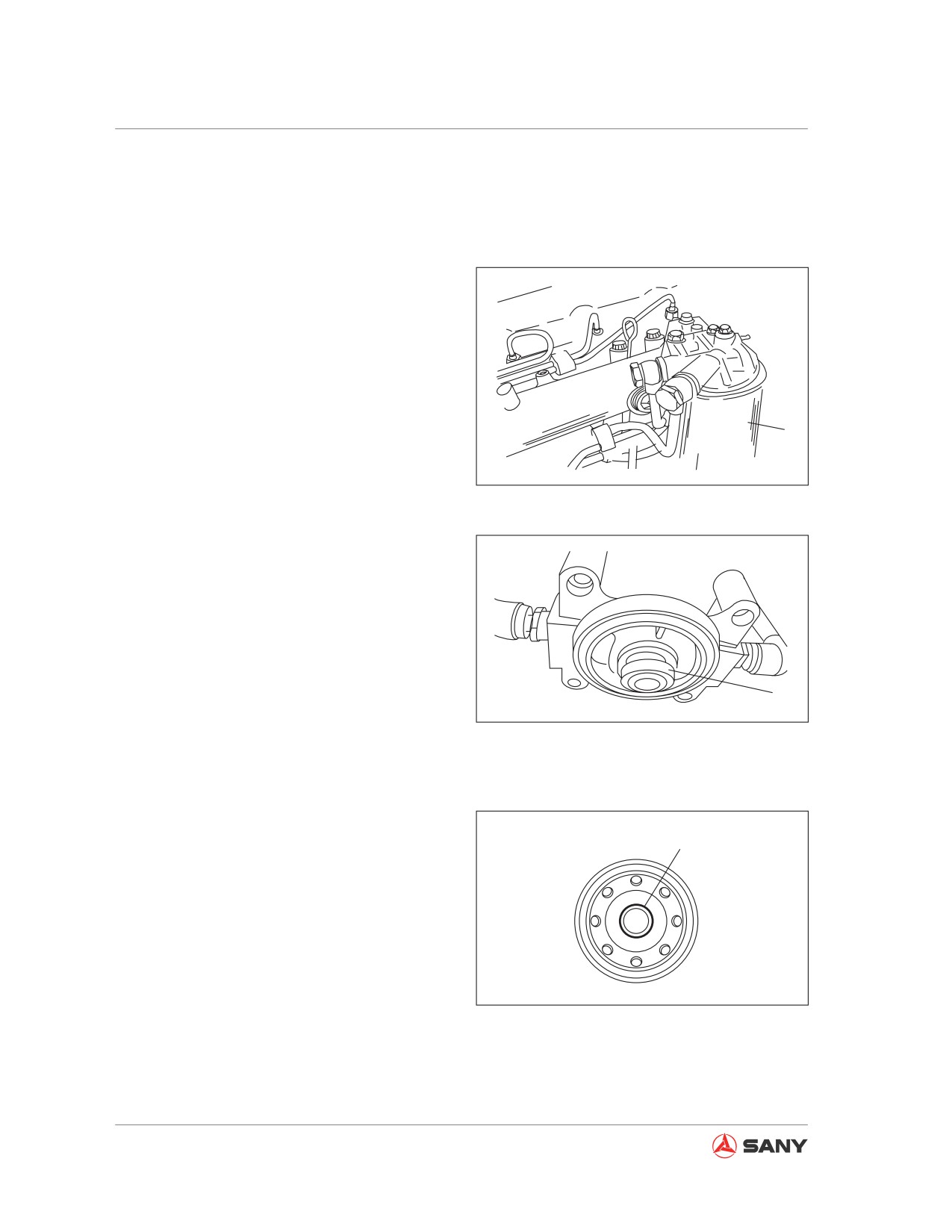
1. Open engine hood.
2. Place a fuel container under the filter.
3. Use filter wrench to turn counterclockwise
the filter (1) in order to remove it.
4. Clean the filter seat. Apply a thin layer of
1
oil to sealing surface of filter cartridge and
install filter cartridge to filter seat.
CZ335-1104089
Replace internal seal (2) with a new one.
Fig. 5-69
2
CZ335-1104090
Fig. 5-70
Note:
● Never add fuel to new filter cartridge.
B
● Remove cap (B) and install filter cartridge.
CZ335-1104091
Fig. 5-71
5-72
Maintenance
5. Tighten filter cartridge until the seal con-
tacts filter seat. Further turn it by 3/4 turn.
If filter cartridge was over-tightened, the
seal might be damaged and fuel leak could
result. If filter cartridge was not tightened
enough, fuel will leak through the gap
of seal. Always tighten it to the specified
torque.
3
6. Remove air after replacing the filter.
Air-purging steps:
7. Refill fuel tank until the float reaches the
maximum level.
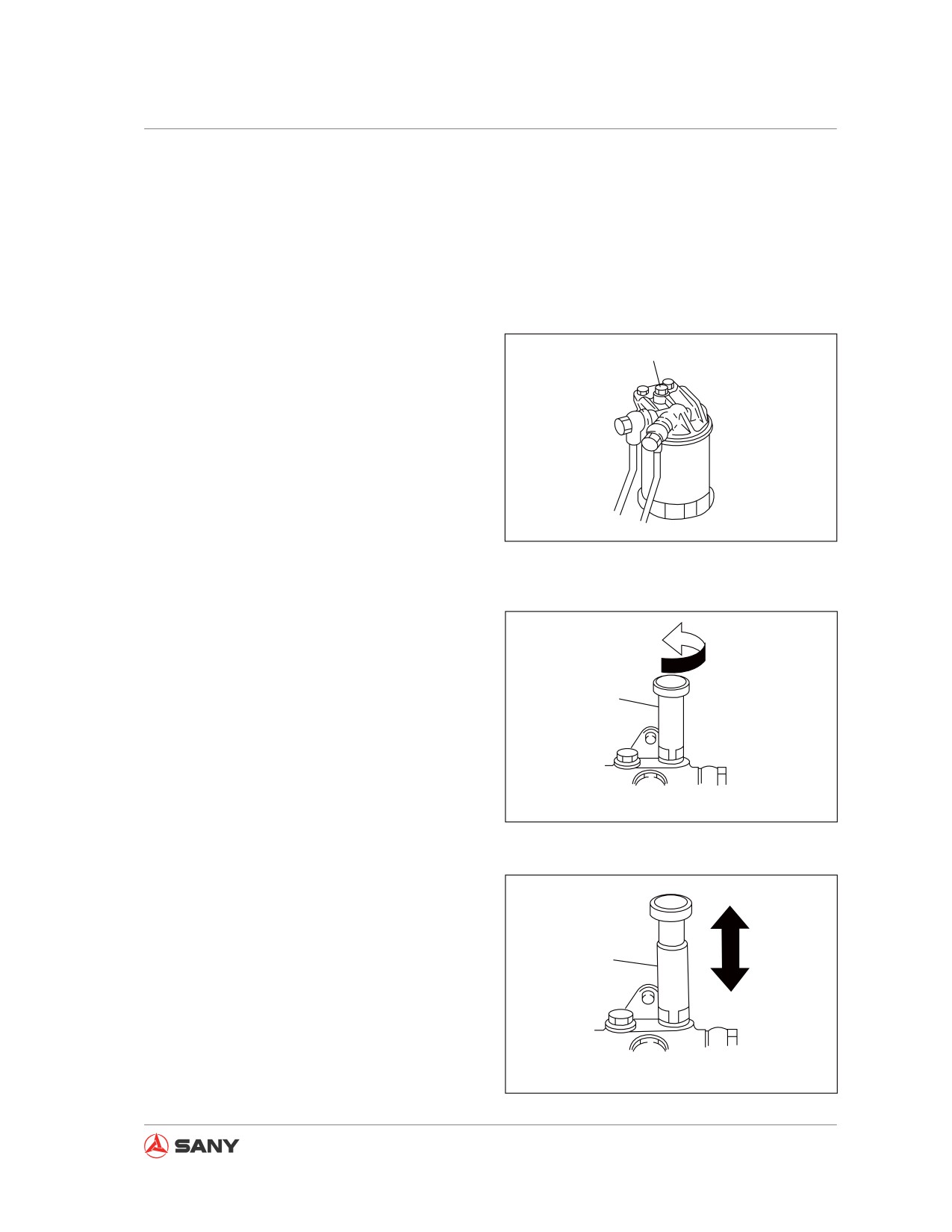
8. Loosen plug (3) of fuel filter.
CZ215-1104016
Fig. 5-72
9. Turn counterclockwise the handle (4) of
start priming pump.
10. Push and pull the handle (4) to pump fuel.
11. Tighten plug (3) when fuel coming out of
plug of fuel filter contains no foam.
4
Tightening torque: 9.8±2.0 N·m {1.0±0.2
kgf·m}
12. Operate the priming pump 5-6 times and
Start priming pump
CZ215-1104017
turn handle (4) clockwise to tighten it.
Fig.
5-73
13. Completely remove overflowed fuel after
purging the air. Start the engine and run it
at low idle for 10 minutes.
Check filter cartridge for fuel leak. Check
the tightening of filter cartridge if fuel leak
4
is found.
If fuel leak still exists, repeat step 1 through
step 3 to remove the cartridge. If seal dam-
age or impurities are found, repeat step 4
Start priming pump
through step 13 to install a new cartridge.
CZ215-1104018
Fig.
5-74
5-73
Maintenance
5.8.6 Every 500 service hours
Also perform maintenance for every 100 and
250 service hours is in the meantime.
5.8.6.1 Swing bearing - lubricate
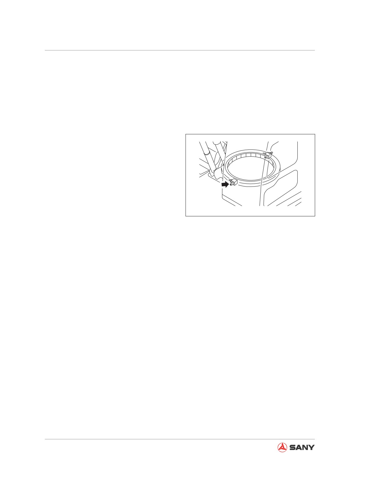
1. Lower work equipment to ground, stop
the engine and engage hydraulic lockout
control.
2. Add grease through two grease fittings
while the upper structure is kept static.
3. Start the engine, disengage hydraulic
lockout control and raise the bucket 20-30
mm off ground. Swing upper structure by
CZ135B-1104021
45 degrees and add grease through steps
1 and 2.
Fig. 5-75
4. Repeat step 3 twice to accomplish greas-
ing.
Note:
● The grease is used to prevent distortion
and noise of joints.
● It is necessary to add grease to any com-
ponent that appears inflexible or noisy after
operation for a long period.
● Wipe off the used grease that has been
squeezed out when greasing.
● Make sure to wipe off all used grease in
different locations. Using a grease that has
been contaminated by sand or debris can
lead to wear of rotating components.
5-74
Maintenance
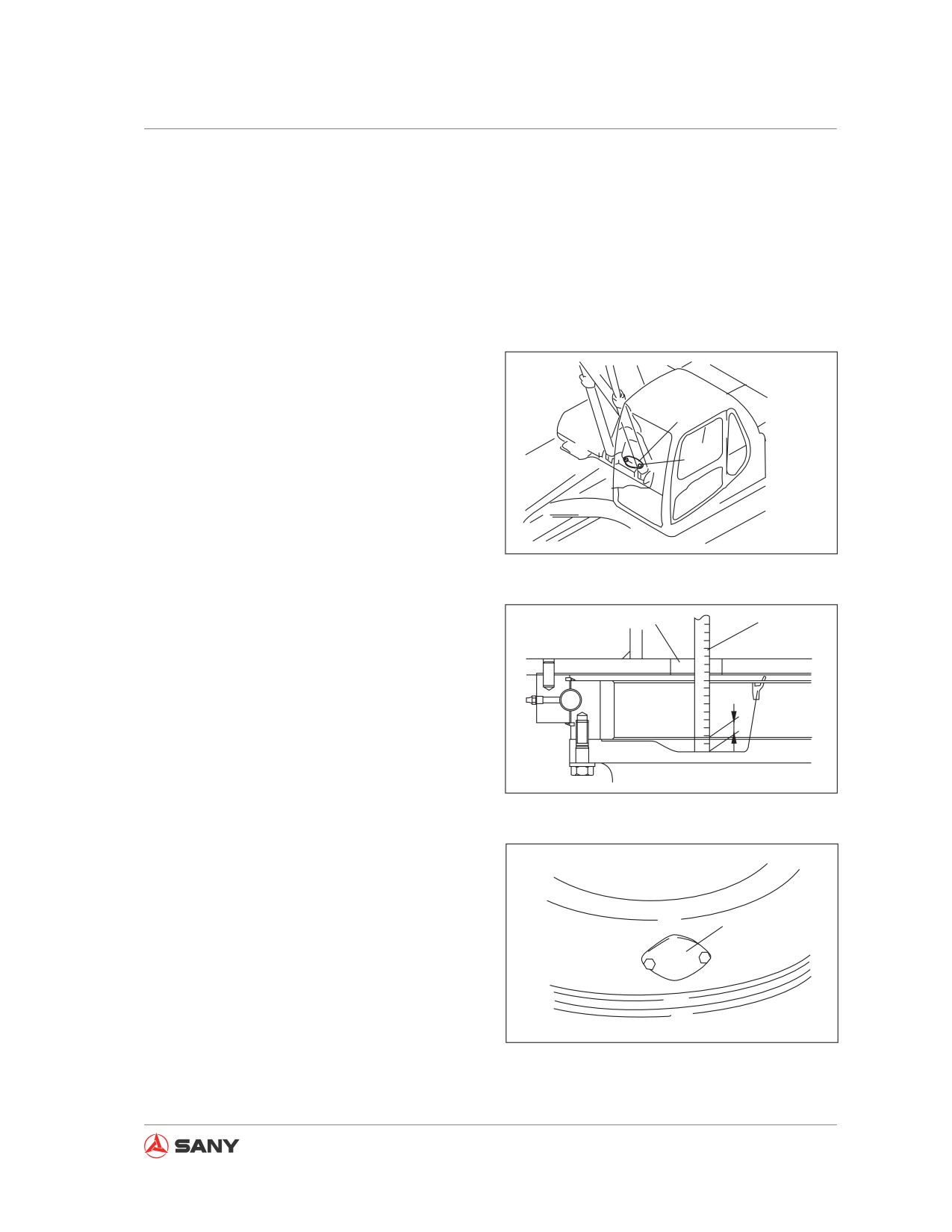
5.8.6.2 Swing pinion gear grease - check/refill
Always prepare your machine as required
and lock/tag it out before proceeding. See
“Preparing the machine” on page 2-58 and
“Lock-out and tag-out” on page 2-60.
● Prepare a dipstick.
1. Remove the two bolts (1) from the swing
frame. Remove the cover (2).
2. Insert the dipstick (3) into the grease
2
through the hole for inspection and
adjustment. Check the grease level, which
1
should be 14 mm (0.6 in) at minimum, at
where the pinion gear passes.
3. Check the grease to see whether it is milk-
CZ335-1104068
white. Milk-white grease indicates that the
grease has been contaminated. Consult
Fig.
5-76
Sany distributor in order to change the
grease.
A
3
Total grease volume: 15 L (3.97 US gal)
S
CZ335-1104069
Fig. 5-77
4. Use the bolts (1) to reinstall the cover (2).
2
CZ335-1104070
Fig. 5-78
5-75

Maintenance
5.8.6.3 Coolant tank and radiator fins - inspect/clean
WARNING
If you are directly impacted by compressed air, pressurized water or steam, or you use
them to purge dirt or debris, personal injury could result. Make sure you are well protect-
ed by wearing goggles, dust-proof mask or other protective gear.
Note:
1
When compressed air is used for cleaning, it
is important to use the air at certain distance
in order to avoid damaging the radiator fins.
Damage of radiator fins will lead to water
leakage and overheating. Working in a dusty
place, the fins shall be inspected on each
workday despite of the service schedule.
CZ135B-1104023
Always prepare your machine as required
Fig. 5-79
and lock/tag it out before proceeding. See
“Preparing the machine” on page 2-58 and
“Lock-out and tag-out” on page 2-60.
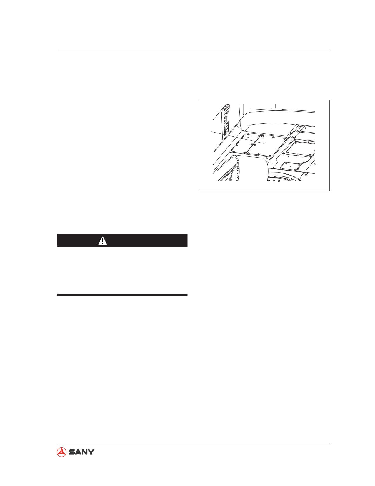
1. Open engine hood (1).
4
2. Loosen screws (3) and (8). Pull up screens
(2) and (9).
8
9
3. Clean the screens.
7
CZ135B-1104024
4. Inspect the coolant tank (4), intercooler
fins (5), A/C condenser fins (6) and the
Fig. 5-80
hydraulic oil radiator fins (7). Compressed
air can be used to remove dirt and leaves
3
sticking to the fins.
6
Steam or water can also be used to clean
the fins.
5
However, a safe distance to the machine
2
shall be kept when cleaning the heat ex-
changers (of radiator, oil cooler, intercooler
CZ135B-1104025
Fig. 5-81
5-76
Maintenance
and air conditioner condenser) with power-
ful steam (from high-pressure flushing ma-
chine). With steam cleaning (high-pressure
machine flushing) at a near distance, the
heat exchanger could deform and early
plugging and cracking could be resulted.
5. Inspect rubber hoses. Replace the hoses
10
in case of cracking or aging. Check hose
clamps for looseness.
6. Remove bottom cover (10). Remove dirt,
debris and tree leaves that have been
swept to the outside.
CZ135B-1104026
7. Reinstall cleaned screens (2) and (9) and
tighten them with screws (3) and (8).
Fig. 5-82
5.8.6.4 Air conditioner filters - clean
WARNING
The dust blown by compressed air could
cause personal injury. Make sure you are
protected by goggles, dust-proof mask
and other protective gear.
Note:
The filter shall be cleaned every 500 hours,
but operating your machine in a dusty place
requires cleaning the filter more frequently.
Remark:
An air filter plugged with dust will reduce air
flow and cause the air-conditioning unit to pro-
duce noise.
Always prepare your machine as required
and lock/tag it out before proceeding. See
“Preparing the machine” on page 2-58 and
“Lock-out and tag-out” on page 2-60.
5-77
Maintenance
Cleaning the filter screen
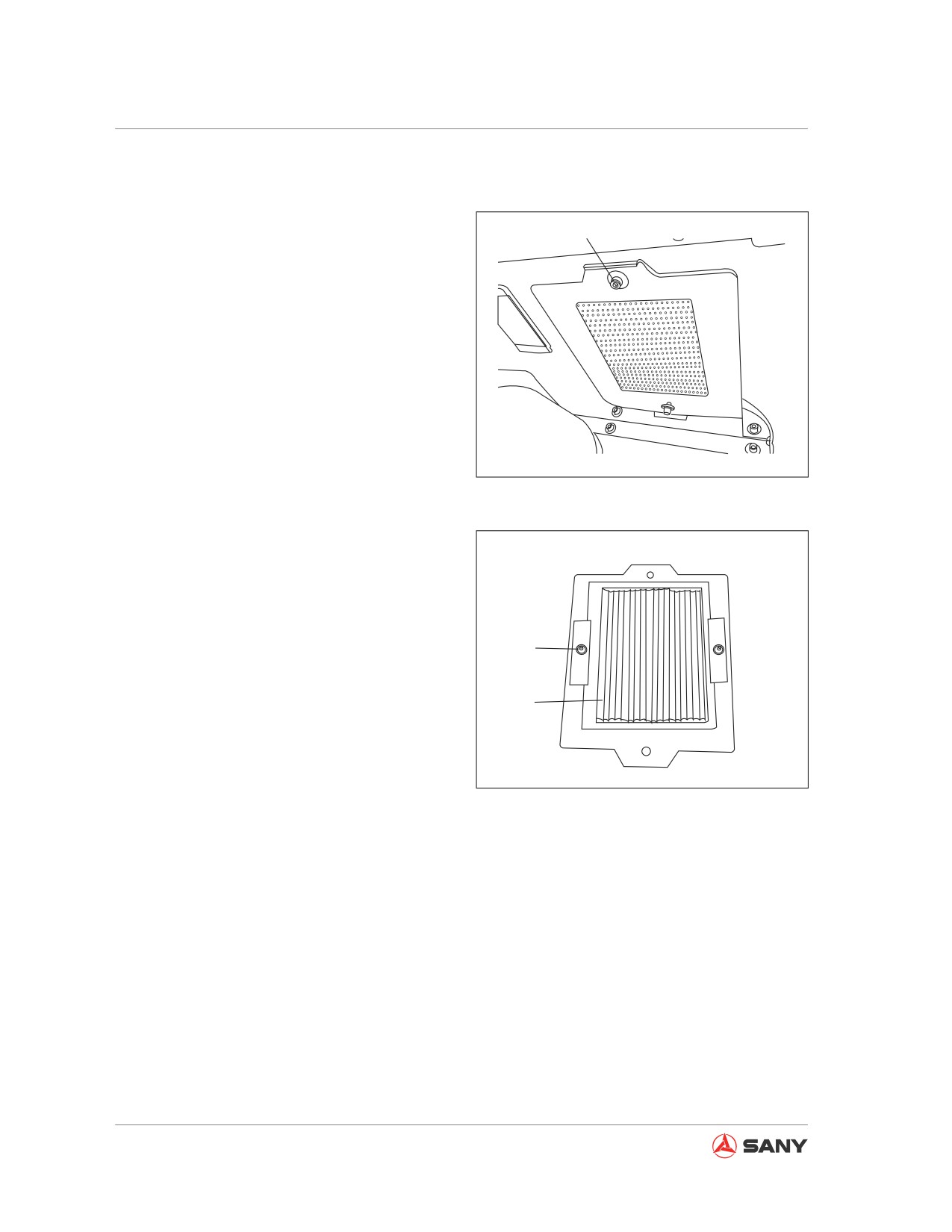
1. Remove the screw (1) from the access
1
window located on the left rear bottom of
the cab, loosen the locking nut (2) and
remove the air recirculation filter (3).
2. Use compressed air to clean the filter. If
the filter bears oil or too much dirt, clean it
with moderate detergent. After the filter has
been flushed with water, it must be dried
completely before reuse. This filter shall
be replaced every year with a new one. If
a plugged air filter cannot be cleaned with
compressed air or flushing water, replace it
CZ335-1104075
immediately.
Fig. 5-83
2
3
CZ335-1104076
Fig. 5-84
5-78
Maintenance
Cleaning the fresh air filter
1.
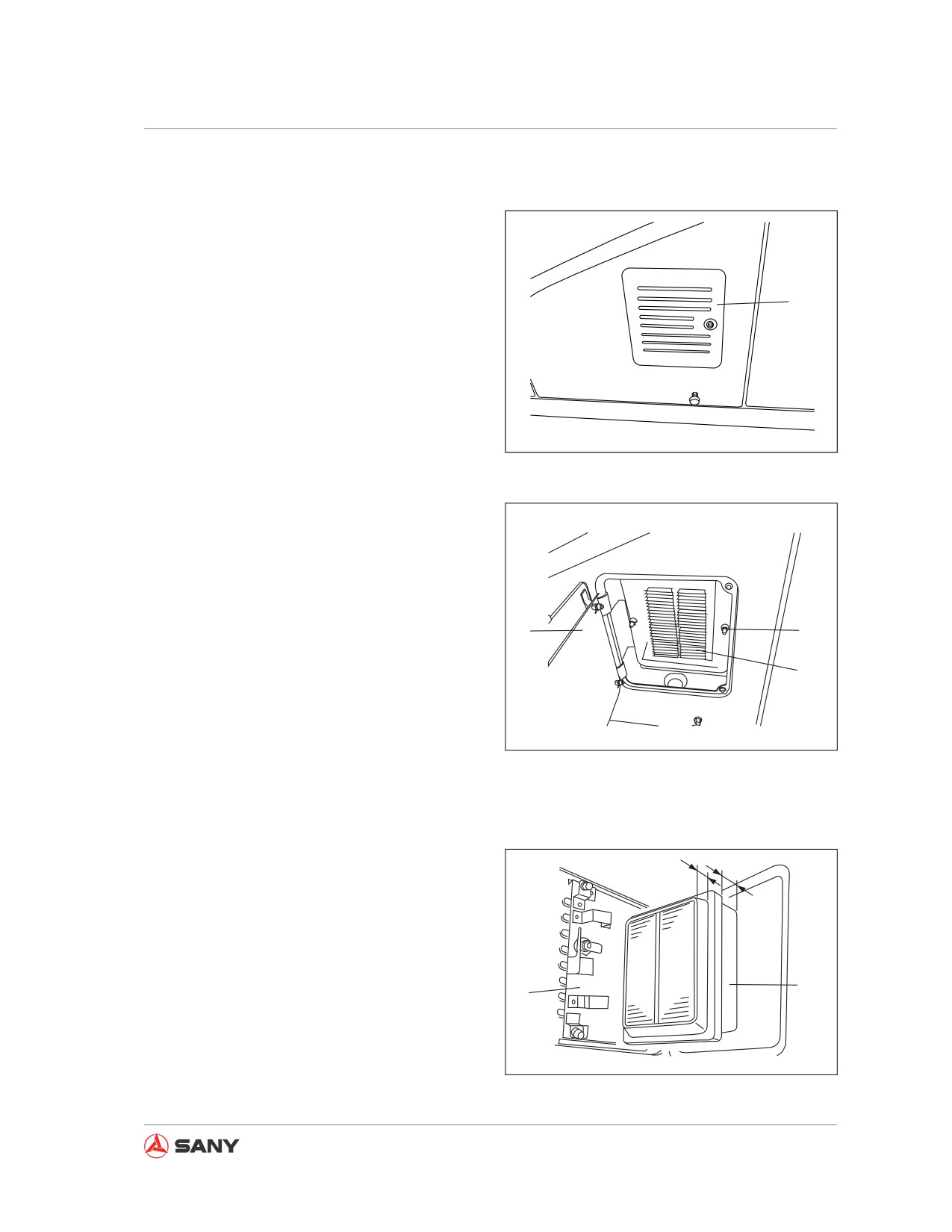
Unlock the rear cover (4) on the left side
of the cab with the start switch key. Open
the cover (4) with your hand, remove the
locking nut (5) and take out the fresh air
filter (6).
4
2.
Use compressed air to clean the filter. If
the filter bears oil or too much dirt, clean it
with moderate detergent. After the filter has
been flushed with water, it must be dried
completely before reuse. This filter shall
CZ335-1104077
be replaced every year with a new one. If
a plugged air filter cannot be cleaned with
Fig.
5-85
compressed air or flushing water, replace it
immediately.
3.
After cleaning, restore the filter (6), tighten
the nut (5) and close the cover. Lock the
cover with your start switch key and then
remove the key.
4
5
6
CZ335-1104078
Fig. 5-86
Remark:
The fresh air filter must be installed correctly.
S
To install the filter, the long end (L) of the filter
(6) must be inserted first into the filter box. By
L
inserting the short end (S), the cover (4) will
not be closed.
6
4
CZ335-1104079
Fig. 5-87
5-79
Maintenance
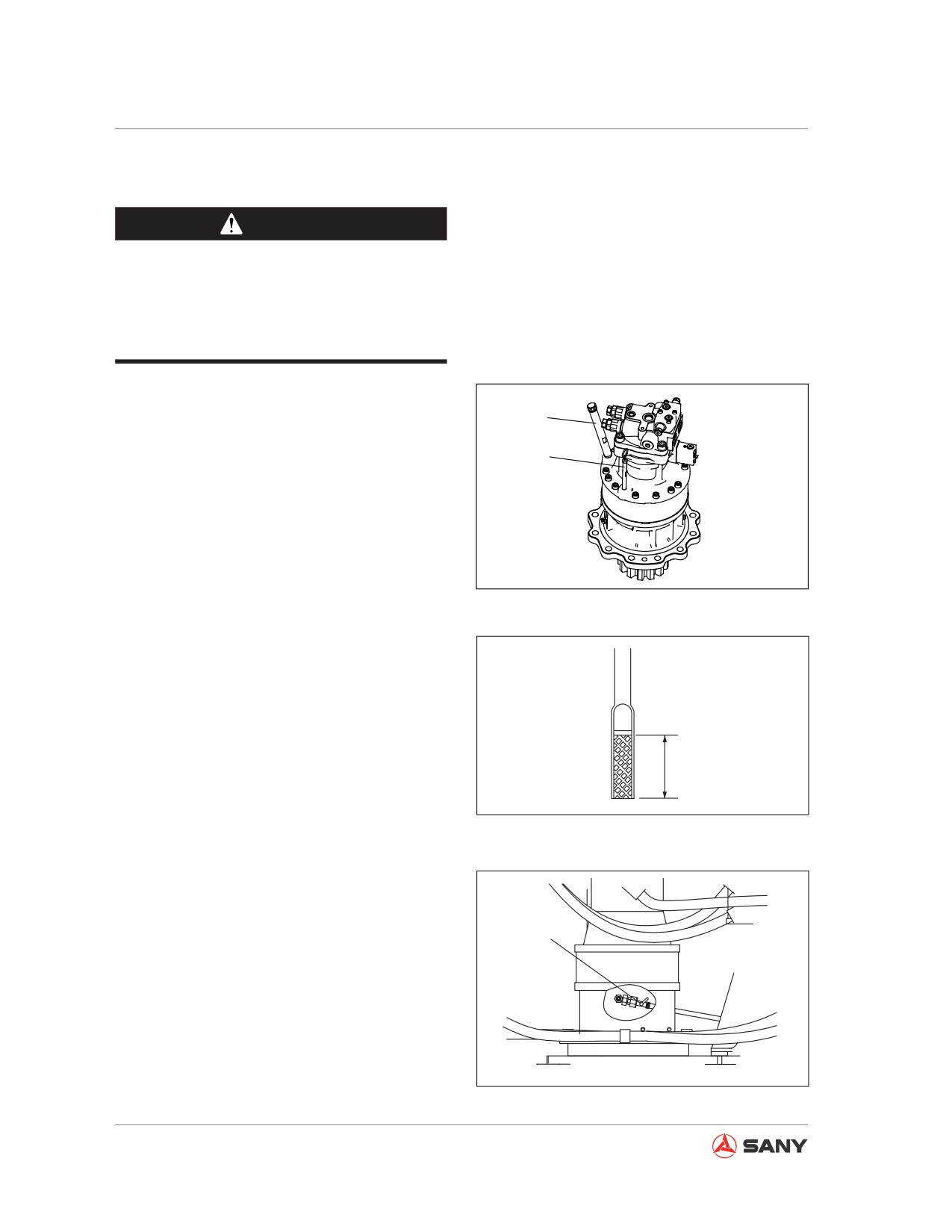
5.8.6.5 Swing drive oil - check/refill
WARNING
When the engine has just been stopped,
the parts and oil are still hot and can
cause serious burn. Wait until they are
cool enough before doing the job.
Always prepare your machine as required
and lock/tag it out before proceeding. See
F
“Preparing the machine” on page 2-58 and
“Lock-out and tag-out” on page 2-60.
G
1.
Remove the dipstick (G) and wipe off the
oil.
2.
Insert the dipstick (G) completely into the
filter tube.
CZ135B-1104027
Fig. 5-88
3.
Take out the dipstick (G) and check
whether the oil level is between the H and
L marks.
4.
If the oil level is lower than the L mark on
the dipstick (G), remove the filler cap and
add oil.
H
5.
If the oil level is higher than the H mark on
the dipstick (G), loosen the drain valve (P)
L
CZ335-1104083
to drain excessive oil.
Fig. 5-89
● If the oil level is too high, consult Sany
distributor for inspection.
● Place a container under the drain valve
before draining the oil.
P
6.
After checking the oil level or refilling the
oil, insert the dipstick (G) into the hole and
restore the filler cap.
CZ335-1104084
Fig. 5-90
5-80
Maintenance
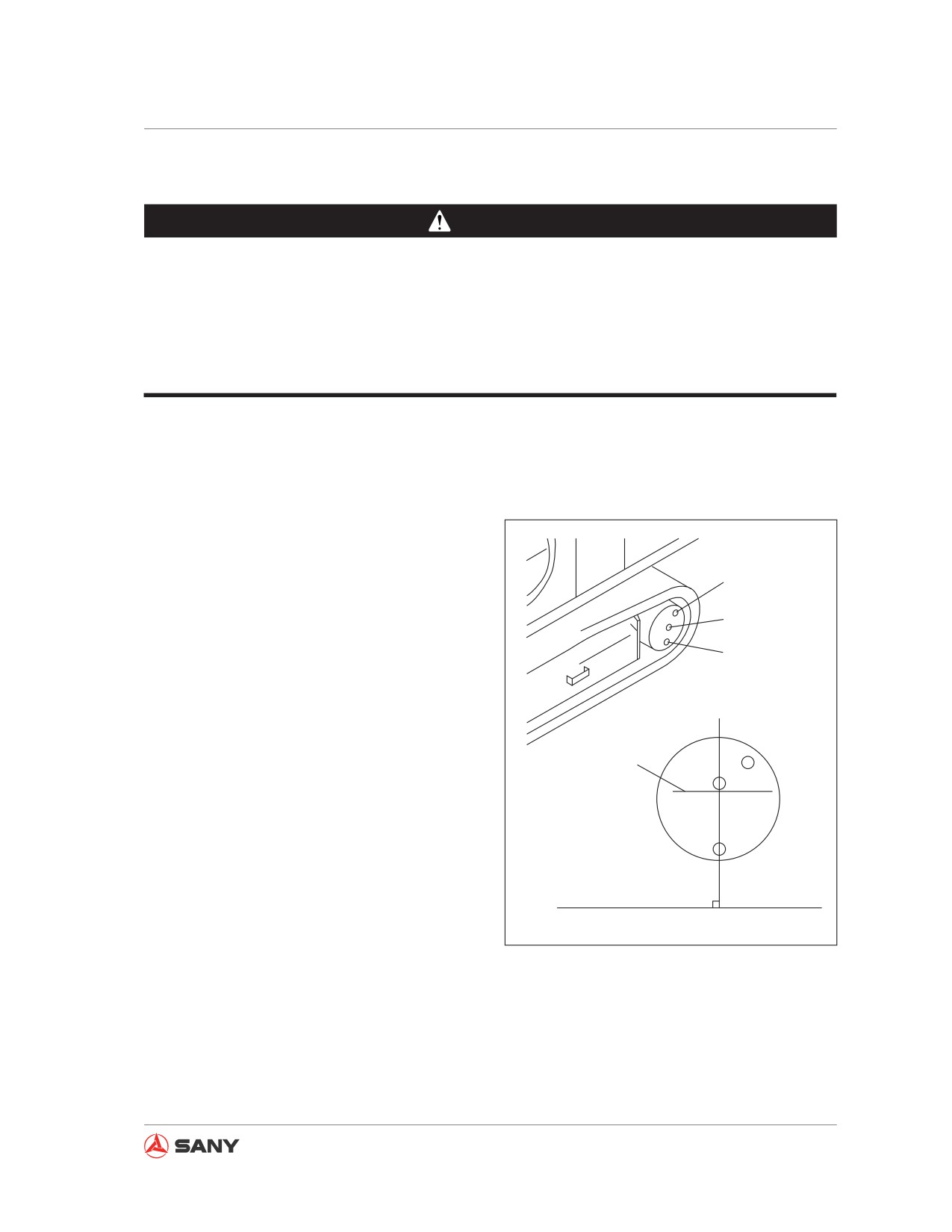
5.8.6.6 Final drive oil - check/fill
WARNING
● When the engine is shut down, the oil is still hot. Wait until the oil is cool enough be-
fore operation.
● Remaining pressure in the tank can cause oil to squirt out or the screw plug to fly out.
Slowly loosen the screw plug in order to release the pressure.
● When the screw plug is loosen, do not stand in front of the screw plug.
Always prepare your machine as required
and lock/tag it out before proceeding. See
“Preparing the machine” on page 2-58 and
“Lock-out and tag-out” on page 2-60.
●
Refilling volume: 5.5 L (1.45 US gal)
●
Prepare a 10 mm wrench.
F
1.
Adjust the filler cap screw (F) to the upper
position in order to make the line through
L
the oil inspection screw plug (L) and the
P
drain screw plug (P) perpendicular to the
ground.
2.
Use a proper screwdriver to eliminate the
dirt from the hexagonal socket of screw
Level mark
plug in order to avoid damage to the bolt.
3.
Use a spanner to remove the screw plug
(L). When the oil level reaches the point 10
mm (0.4 in) below the bottom of the screw
plug (L) opening, the amount of oil added
is just perfect.
4.
If the oil level is too low, reinstall the screw
CZ335S-1104020
plug (L), operate the travel level and slowly
travel your machine forward or backward in
Fig. 5-91
order to run the sprocket one turn. Repeat
step 2 and check again.
5.
If the oil level is low, fill oil through the
opening of the screw plug (F) till the oil
overflows through the opening of the screw
plug (L).
5-81
Maintenance
6. When the oil level is too high, consult Sany
distributor for inspection.
7. Restore the screw plugs (F) and (L) after
check and tighten them to: 58.8±19.6N.m.
5.8.7 Every 1000 service hours
Also perform maintenance for every 100, 250
and 500 service hours in the meantime.
5.8.7.1 Hydraulic oil filter - replace
WARNING
When the engine has just been stopped,
the parts and oil are still hot and can cause
serious burn. Wait for the temperature to
cool down before doing the job.
Note:
For machines equipped with a hydraulic
breaker, the hydraulic oil deteriorates faster
than that of machines operating with a bucket.
For more information see “Hydraulic Break-
er Service Interval” on page 5-27.
5-82
Maintenance
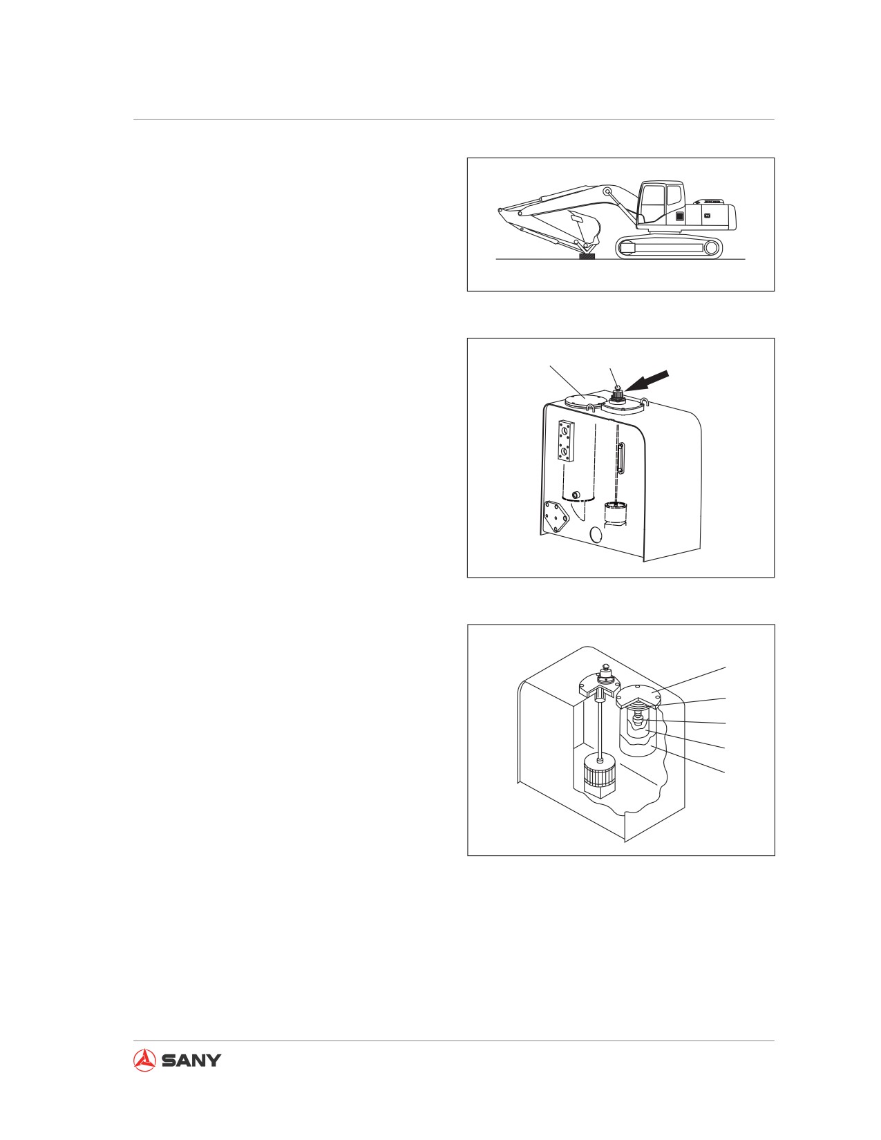
1.
Park your machine on a hard, level ground.
Adjust the work equipment to an attitude
ready for service, as shown in the right
illustration. Lower the work equipment to
ground and turn off the engine.
2.
Lock out and tag out your machine before
CZ335-1104086
proceeding. See “Lock-out tag-out” on
Fig. 5-92
page 2-60.
3.
Turn the butterfly nut on the breather valve
Butterfly nut
1
Breather valve
and press the venting button.
4.
Loosen the four bolts and remove the cap
(1). When the cap is removed, it may fly
out due to the action of the spring (2). In
this case, hold down the cap when remov-
ing the bolts.
5.
Remove the spring (2), valve (3) and
strainer (4) before disassembling the filter
(5).
CZ335-1104087
● Check the bottom of the filter box and
Fig. 5-93
remove the dirt if any. Keep the hydrau-
lic oil free from any dirt.
6.
Clean the disassembled parts with clean-
1
ing oil.
2
7.
Install a new filter.
3
4
8.
Restore the valve (3), strainer (4) and
spring (2).
5
9.
Install the cap (1) to its position. Hold down
the cap and tighten the bolts.
CZ335-1104088
10. In order to vent the air, start the engine
Fig. 5-94
(see "Engine Starting" in the Operation
Section) and run the engine at low idle for
10 minutes.
11. Stop the engine.
5-83
Maintenance
5.8.7.2 Swing drive oil - change
WARNING
When the engine has just been stopped,
the parts and oil are still hot and can
cause serious burn. Wait until they are
cool enough before doing the job.
Always prepare your machine as required
and lock/tag it out before proceeding. See
“Preparing the machine” on page 2-58 and
“Lock-out and tag-out” on page 2-60.
● Tank capacity:
3.5 L (1.06 US gal)
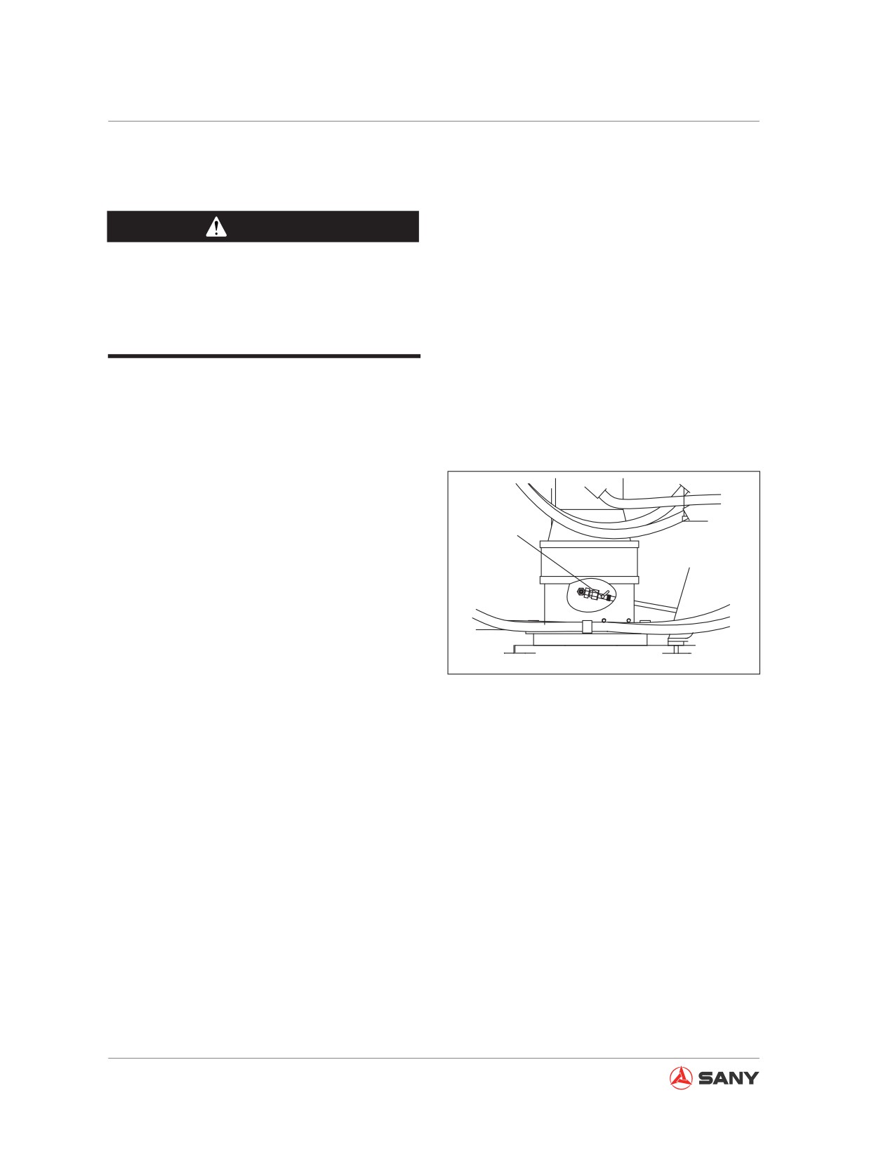
P
1. Place a container under the drain valve (P)
in order to contain the gear oil drained.
2. Loosen the drain valve (P) beneath the
machine to drain the gear oil. Tighten the
drain valve upon completion of the drain-
ing.
CZ335-1104084
Fig. 5-95
Remark:
● If the gear oil flows out in a thin thread pat-
tern, you can end the draining operation.
● When the temperature is low, you can
swing the work equipment to slightly in-
crease the oil temperature before draining
the oil. However, the work equipment shall
not be swung during draining, which may
otherwise damage the swing unit.
5-84
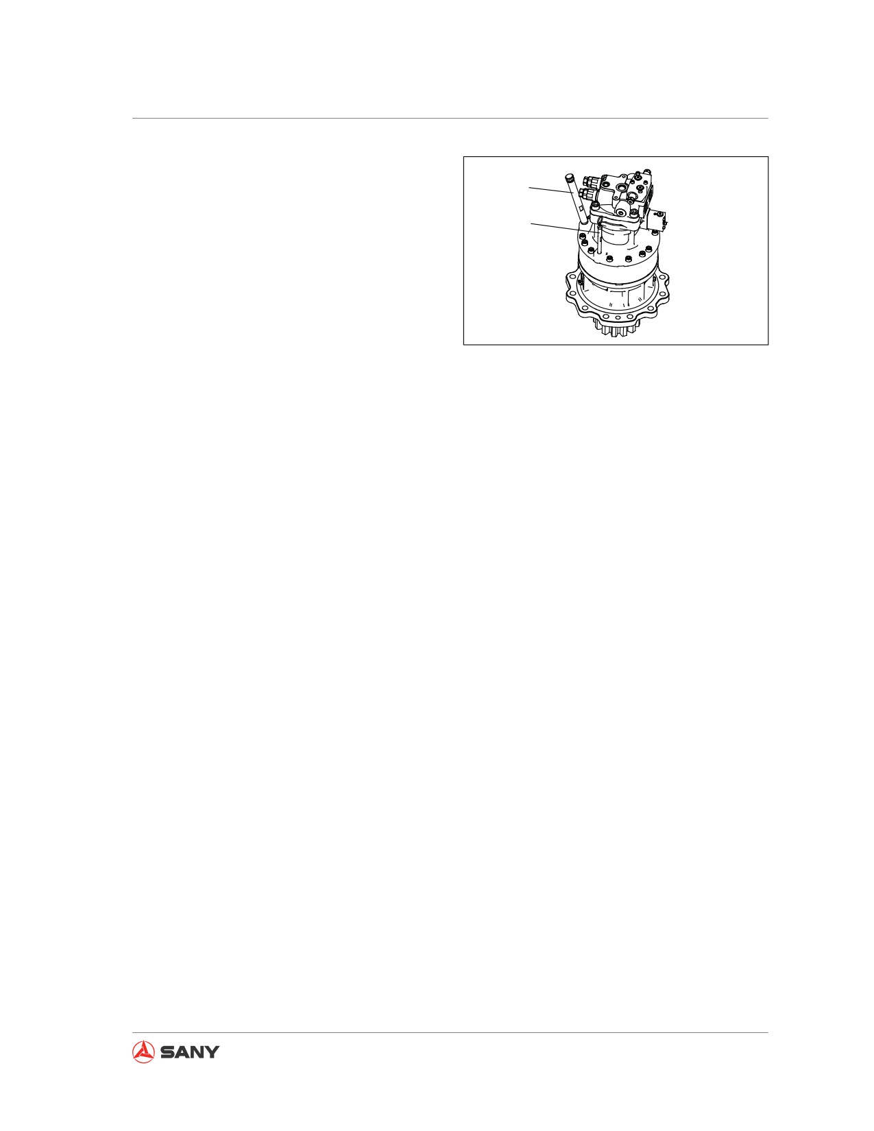
Maintenance
3. Remove the filler cap (F) and fill the oil as
required through the filler opening (F).
F
4. Check the oil level. For more information
G
see “Swing drive oil - check/refill” on
page 5-80.
5. For information on selection of oil and tem-
perature see “Recommended Fluids”
CZ135B-1104027
on page 5-17.
Fig. 5-96
5.8.7.3 Engine exhaust pipe clamps - check
Consult Sany distributor to check the fastening
conditions of the air cleaner - turbocharger -
post cooler - engine clamps.
5.8.7.4 Fan belt tension - check/replace
Check the tension of fan belt. Replace the fan
belt in case of cracks or damage. Contact your
Sany distributor if you have any troubles.
5.8.7.5 Nitrogen pressure in accumulator
(breaker) - check
(If equipped)
Special tools will be used in order to check the
accumulator and inject nitrogen.
Please consult Sany distributor, if possible, to
conduct related inspection and inflating opera-
tion.
5-85
Maintenance
5.8.8 Every 2000 service hours
Also perform maintenance for every 100, 500
and 1000 service hours in the meantime.
5.8.8.1 Final drive oil - change
WARNING
● When the engine is just shut down, the
oil and components are still hot and
can cause burn. Wait until the oil is cool
enough before servicing.
● Remaining pressure in the tank can
cause oil to squirt out or the screw plug
to fly out. Personal injury could result.
Slowly loosen the screw plug in order
to release the pressure. Never stand in
front of the screw plug.
Always prepare your machine as required
and lock/tag it out before proceeding. See
“Preparing the machine” on page 2-58 and
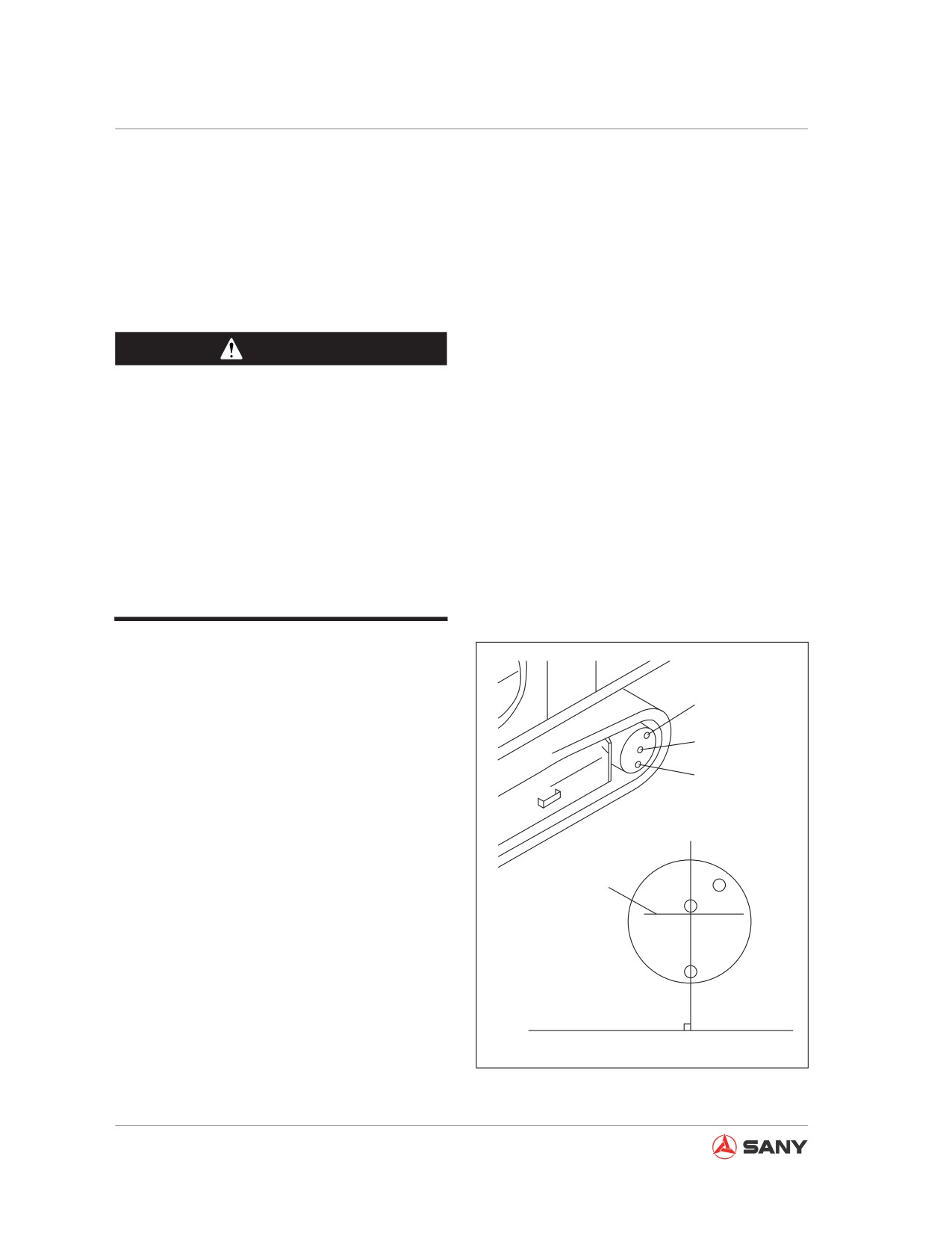
F
“Lock-out and tag-out” on page 2-60.
L
● Refilling capacity:
See “Fluid capacities” on page 5-19.
P
● Prepare a wrench.
1. Adjust the filler cap screw (F) to the upper
position in order to make the line through
Level mark
the oil inspection screw plug (L) and the
drain screw plug (P) perpendicular to the
ground.
2. Use a proper screwdriver to eliminate the
dirt from the hexagonal socket of screw
plug in order to avoid damage to the bolt.
3. Place under the drain plug (P) a container
CZ335S-1104020
used to contain the oil.
Fig. 5-97
4. Use the spanner to remove the drain plug
5-86
Maintenance
(P) in order to drain the oil.
Remark:
Check the O-ring on screw plug and replace
the O-ring if broken.
5. Tighten the plug (P) and remove the plugs
(F) and (L).
6. Fill oil through the opening of the plug (F).
7. When the oil is seen coming out of the
opening (L), reinstall the plug (F) and (L)
and tighten them to: 58.8±19.6N.m.
5-87
Maintenance
5.8.8.2 Hydraulic tank filter screen - clean
WARNING
When the engine has just been stopped,
the parts and oil are still hot and can cause
serious burn. Wait until they are cool
enough before doing the job.
Always prepare your machine as required
and lock/tag it out before proceeding. See
“Preparing the machine” on page 2-58 and
“Lock-out and tag-out” on page 2-60.
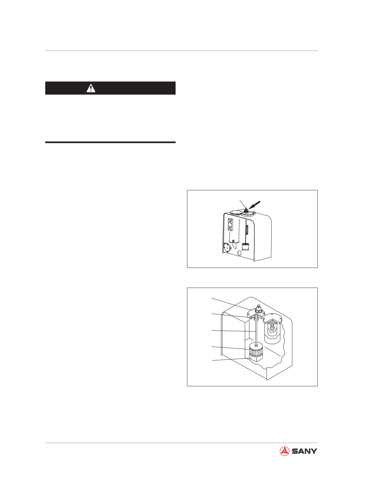
1.
Turn the butterfly nut on the breather valve
Butterfly nut
Breather valve
and press the venting button.
2.
Loosen the four bolts and remove the cap
(1). When the cap is removed, it may fly
out due to the action of the spring (2). In
this case, hold down the cap when remov-
ing the bolts.
CZ335-1104080
3.
Hold the top end of the rod (3) and pull it
upward in order to remove the spring (2)
Fig. 5-98
and the screen (4).
4.
Clean the screen (4) of all dirt. Flush it with
1
cleaning oil. Replace the screen if dam-
aged.
2
5.
During installation, fix the screen (4) to
3
the bigger part (5) of the oil tank before
assembling.
4
5
6.
When assembling, take advantage of the
bulged part of the cap (1) to hold the spring
(2) before tightening the bolts.
CZ335-1104093
Fig. 5-99
5-88
Maintenance
5.8.8.3 Nitrogen pressure in accumulator (control oil circuit) - check
WARNING
The accumulator contains pressurized nitrogen, which may explode due to improper op-
eration, thus resulting in machine damage and personal injury. The following items must
be observed when handling the accumulator:
● Some pressure remains in the hydraulic circuit. Never face the opening from which oil
may squirt when disassembling a hydraulic device. In addition, loosen the bolts slowly.
● Never dismantle the accumulator.
● Be away from fire sources.
● Never punch or weld the accumulator.
● Never bump or roll the accumulator. Keep it free from any impacts.
● Vent the air completely when handling the accumulator. Consult your Sany distributor
to do this job.
Note:
In continuous operation with low nitrogen pres-
sure in the accumulator, the remaining pres-
sure in hydraulic circuit will not be released
once failure occurs to your machine.
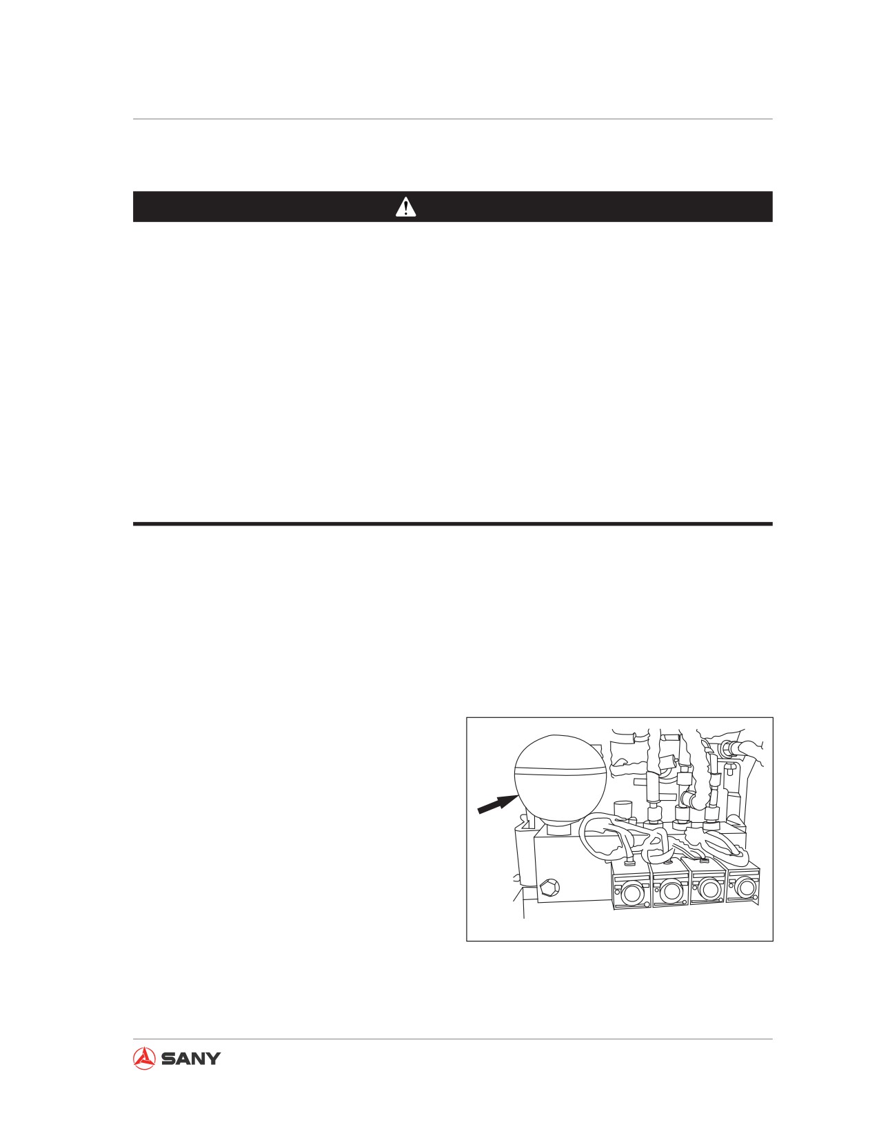
Functions of the accumulator
The accumulator stores the pressure of the
control circuit. Even if the engine is turned off,
the control oil circuit allows you to achieve the
following operations:
● Operate the control lever to lower the work
equipment. The work equipment will fall
due to gravity.
● The pressure in hydraulic circuit can be re-
leased.
The installation location of the accumulator is
CZ135B-1104029
shown in the right illustration.
Fig.
5-100
5-89
Maintenance
Checking the functions of accumulator
NOTICE
During inspection, make sure the sur-
rounding area is clear without personnel
or any barriers.
Check the nitrogen pressure through the fol-
lowing steps:
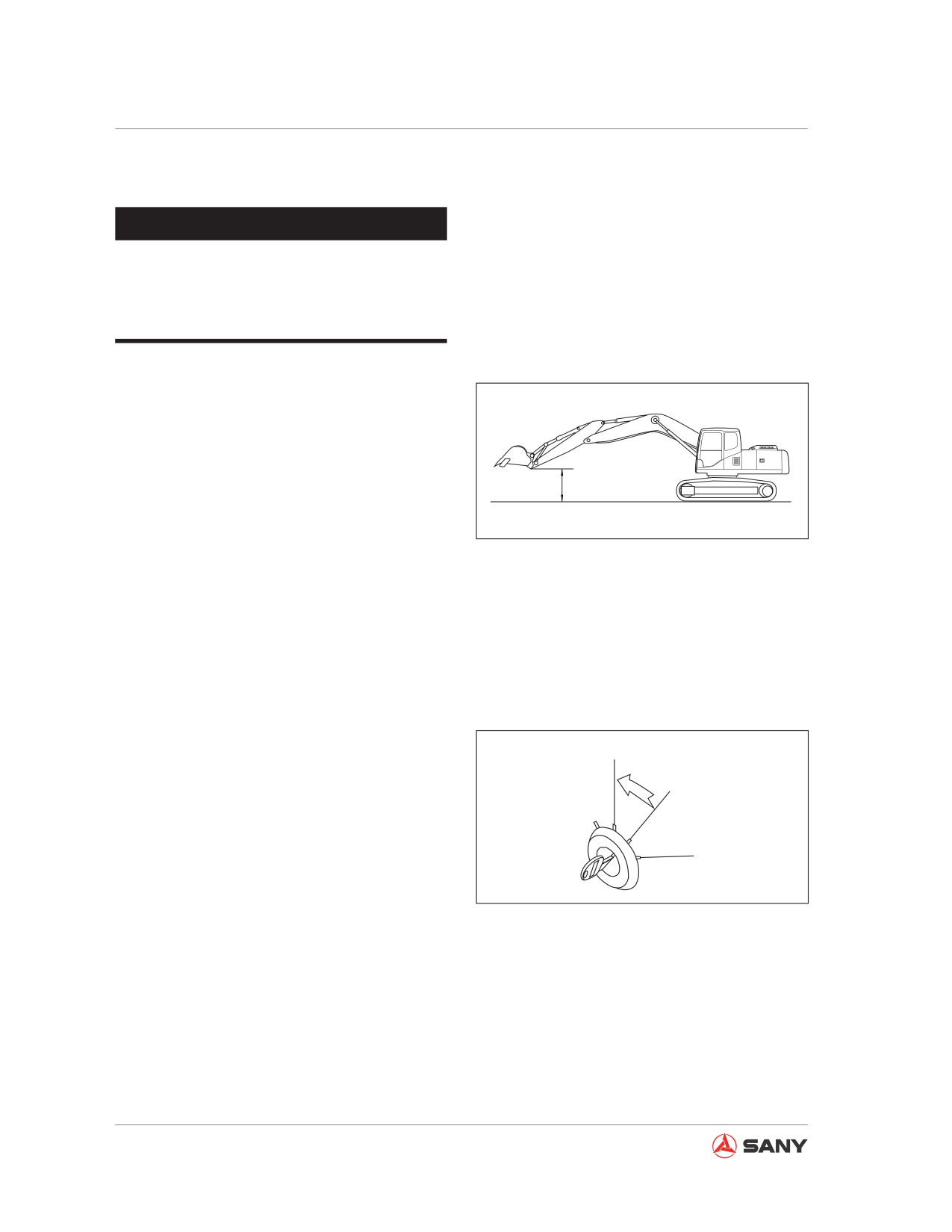
1. Park your machine on a hard, level ground.
2. Keep the work equipment 1.5m (4ft 11in)
1.5m
above the ground at maximum reach (with
the arm fully extended and the bucket fully
CZ335-1104095
turned outward.
Fig. 5-101
The step 3 through step 5 shall be conducted
within 15 seconds.
The accumulator's pressure drops gradu-
ally since stoppage of the engine. Therefore,
check the accumulator immediately after the
engine is shut down.
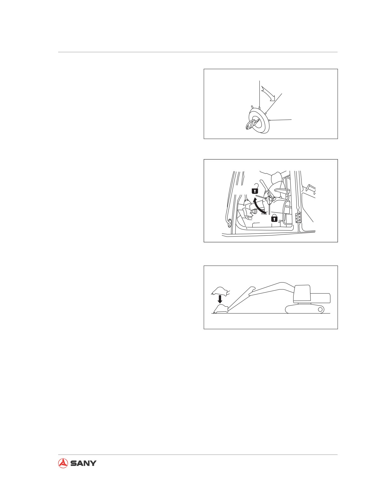
3. Keep the work equipment at its maximum
A
operating radius, turn the start switch to
OFF position (A) and stop the engine.
B
C
CZ335-1104096
Fig. 5-102
5-90
Maintenance
4. Turn the start switch to ON position (B).
A
B
C
CZ335-1104097
Fig. 5-103
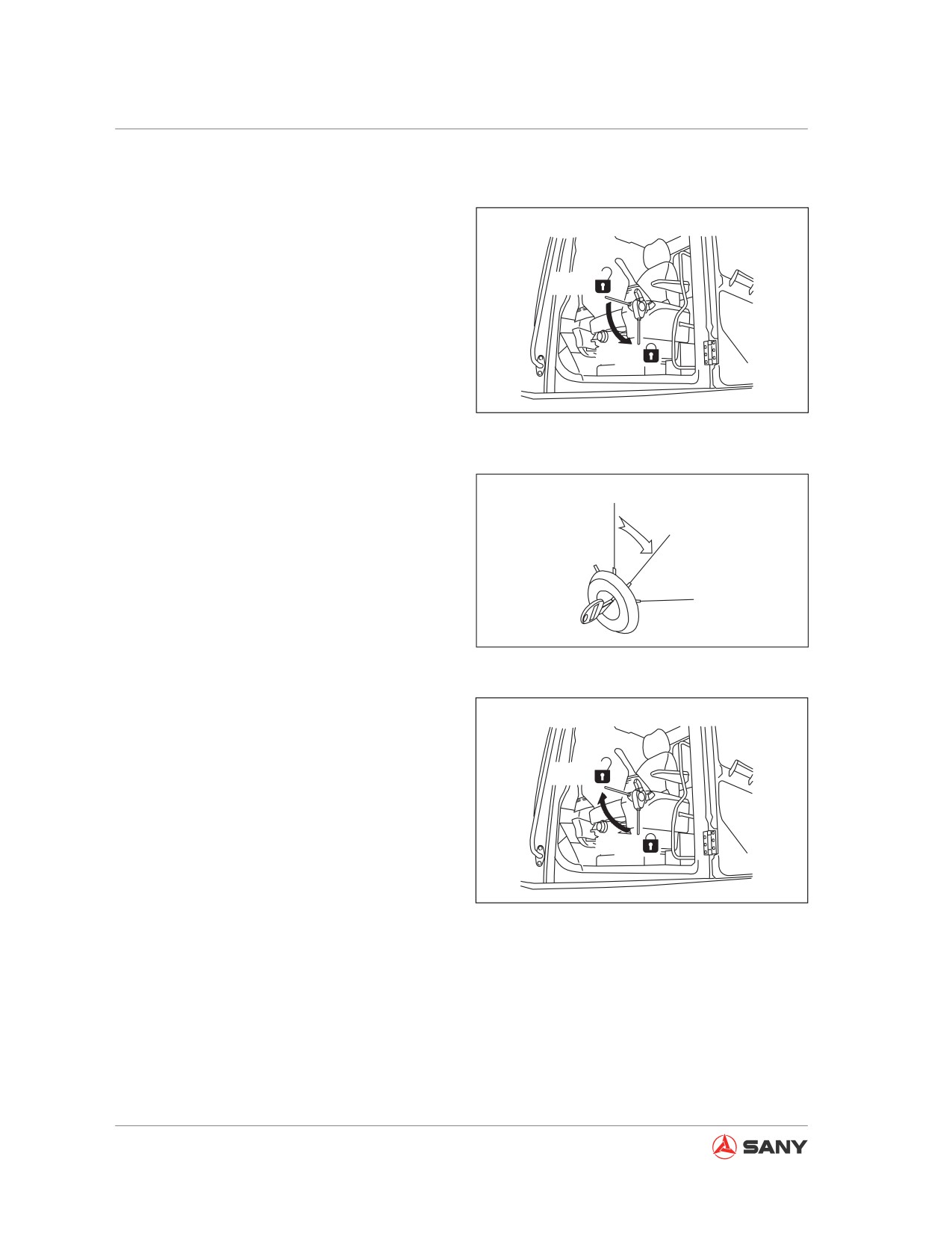
5. Place the lockout control to FREE position
(F). Operate the control lever to lower the
work equipment. Check the work equip-
ment whether it reaches the ground.
F
L
CZ335-1104098
Fig. 5-104
6. A work equipment lowering and touching
the ground under gravity indicates that the
accumulator functions normally.
In case that the work equipment is unable
to lower or is held half way, the pressure in
the hydraulic circuit accumulator may have
CZ335-1104099
dropped already.
Fig. 5-105
Consult Sany distributor for such inspec-
tion.
7. After checking through the a.m. steps,
place the hydraulic lockout control to LOCK
position and turn the start switch to OFF
position.
5-91
Maintenance
5.8.8.4 Hydraulic circuit internal pressure - release
1. Low the work equipment to ground.
2. Place the work equipment lockout control
to the LOCK position (L).
F
The step 4 through step 6 shall be carried
out within 15 seconds.
L
Pressure of the accumulator will drop grad-
ually after the engine is stopped. There-
CZ335-1104100
fore, the pressure can only be released
Fig. 5-106
when the engine has just be turned off.
3. Turn off the engine.
A
4. Turn the start switch to ON position (B).
B
C
CZ335-1104101
Fig. 5-107
5. Place the lockout control to FREE position
(F) and then cycle the work equipment
control lever in all directions in order to
release the pressure in control circuit.
F
6. Place the lockout control to the LOCK
position (L) and then turn the start switch
L
to "OFF" position.
CZ335-1104098
Fig. 5-108
5-92
Maintenance
5.8.8.5 Oil in hydraulic tank - change
WARNING
● When the engine has just been stopped,
the parts and oil are still hot and can
cause serious burn. Wait until they are
cool enough before doing the job.
● Press the breather valve venting button
to release the internal pressure before
removing the oil filler cap.
Note:
For machines equipped with a hydraulic
breaker, the hydraulic oil deteriorates faster
than that of machines operating with a bucket.
For more information see “Hydraulic Break-
er Service Interval” on page 5-27.
● For refilling capacity see“Fluid capaci-
ties” on page 5-19.
● Prepare a lever (used for 36 mm socket
wrenches)
1. Unscrew the bolts of the bottom cover
plate and remove the cover plate.
2. Swing the upper structure in order to posi-
tion the drain plug beneath the hydraulic
CZ335-1104102
tank between the tracks.
Fig.
5-109
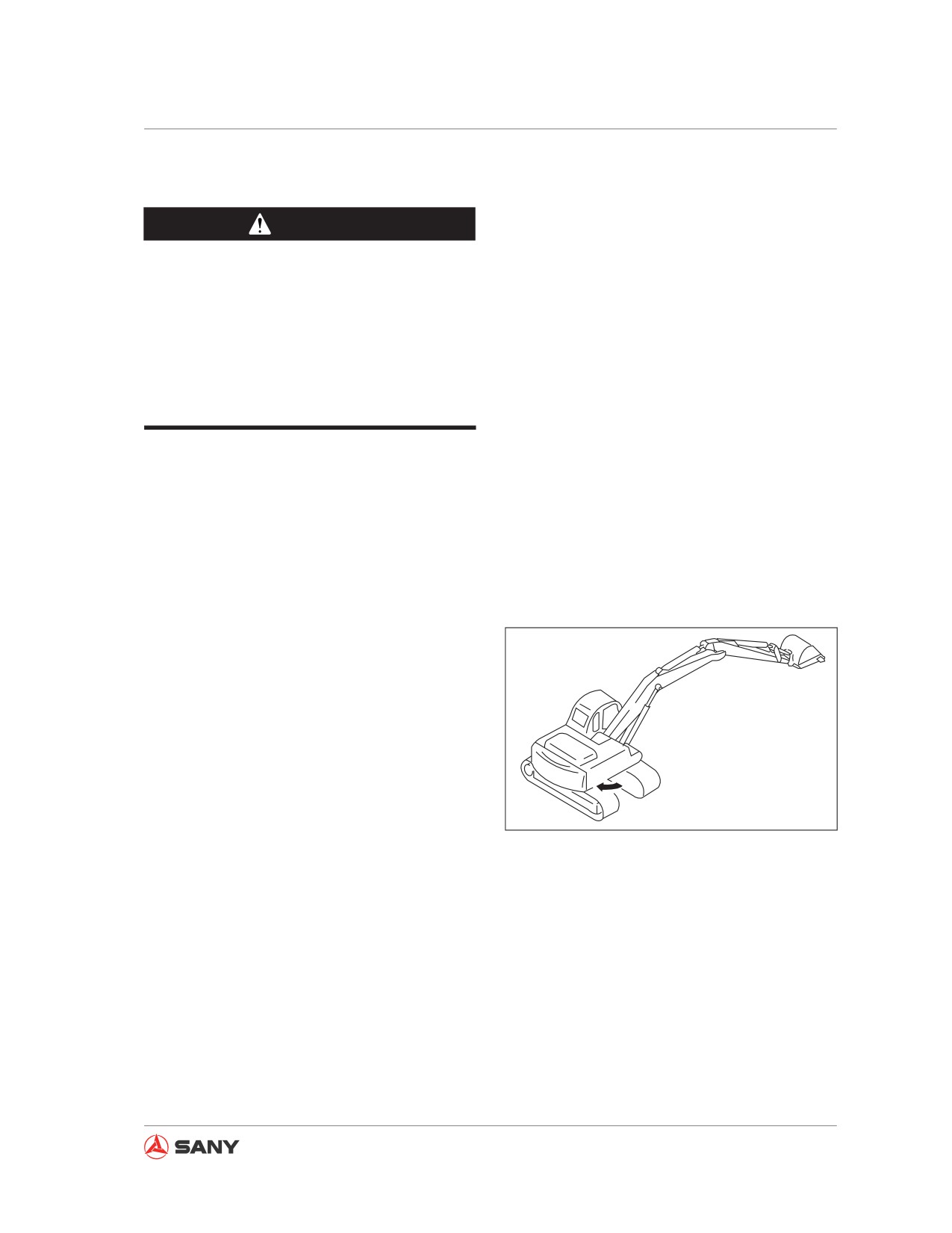
3. Retract the arm and bucket cylinders and
lower the boom in order to enable the
bucket tips to touch the ground.
4. lace the hydraulic lockout control to the
LOCK position and turn off the engine.
5-93
Maintenance
5.
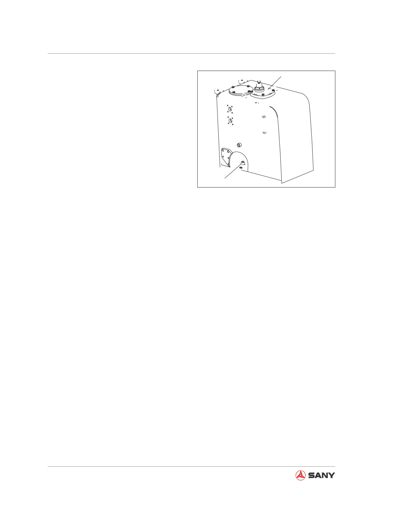
Remove the cap of the oil filler (F) .
F
6.
Place a container under the drain plug.
Remove the drain plug (P) with the lever
in order to drain the oil. Check the O-ring
on the drain plug (P) and replace it timely if
broken. Tighten the plug (P) after draining.
● Tightening torque: 927±103N·m (94.6
± 10.5 kgf·m or 683.5 ± 76.0lbft)
● Do not get oil on your body when re-
moving the drain plug (P).
P
7.
Fill the hydraulic oil as required through the
CZ335-1104103
filler (F). Check the oil level, which shall be
Fig. 5-110
between the H and L marks of dipstick.
● For more information on applicable hy-
draulic oil see “Recommended Flu-
ids” on page 5-17.
● For more information on oil level inspec-
tion see “Cooling system
- clean”
on page 5-37.
8.
Eliminate air from the hydraulic circuit.
For more information on elimination of air
from the hydraulic circuit see “Hydraulic
Breaker Service Interval” on page 5-27.
5-94
Maintenance
5.8.8.6 Alternator - inspect
Contact your Sany distributor to inspect the al-
ternator.
Check the engine every 1000 service hours if
the engine is started frequently.
5.8.8.7 Engine valve clearance - check/
adjust
Special tools are necessary for inspection and
maintenance. Consult Sany distributor to do
this job.
5.8.9 Every 4000 service hours
Also perform maintenance for every 100,
250, 500, 1000 and 2000 service hours in the
meantime.
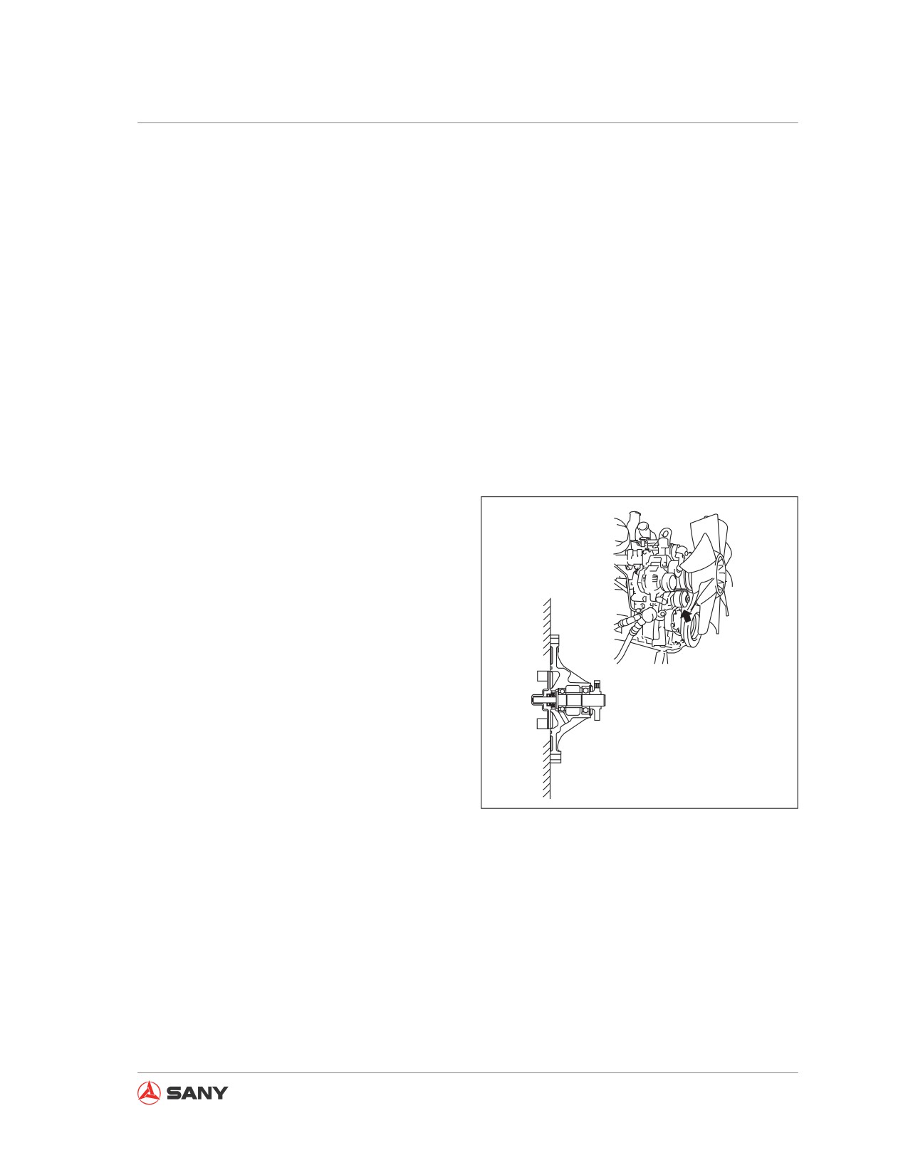
5.8.9.1 Coolant pump - inspect
Check coolant pump for leak of water or oil. In
case of any problem, contact your Sany dis-
tributor for disassembly, repair or replacement.
CZ335-1104104
Fig. 5-111
5.8.9.2 Start motor - check
Consult Sany distributor to check the start mo-
tor. Check it every 1000 service hours if the
engine is started frequently.
5-95
Maintenance
5.8.9.3 Accumulator (control oil circuit) - replace
WARNING
The accumulator contains pressurized
nitrogen, which may explode due to im-
proper operation, thus resulting in machine
damage and personal injury. The following
items must be observed when handling the
accumulator:
● Some pressure remains in the hydrau-
lic circuit. Never face the opening from
which oil may squirt when disassem-
bling a hydraulic device. In addition,
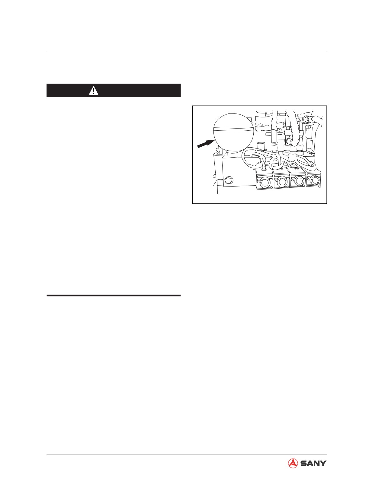
CZ135B-1104029
loosen the bolts slowly.
● Never dismantle the accumulator.
Fig. 5-112
● Be away from fire sources.
● Never punch or weld the accumulator.
● Never bump or roll the accumulator.
Keep it free from any impacts.
● Vent the air completely when handling
the accumulator. Consult your Sany dis-
tributor to do this job.
If your machine is kept operating when the
performance of accumulator decreases, the
pressure in the hydraulic system will not be re-
leased. Consult Sany distributor to replace the
accumulator.
The accumulator's installation location is
shown in the right illustration.
5-96
Maintenance
5.8.9.4 High-pressure tube clamps and rubber - check
CZ335-1104106
Fig. 5-113
Always prepare your machine as required and lock/tag it out before proceeding. See “Preparing
the machine” on page 2-58 and “Lock-out and tag-out” on page 2-60.
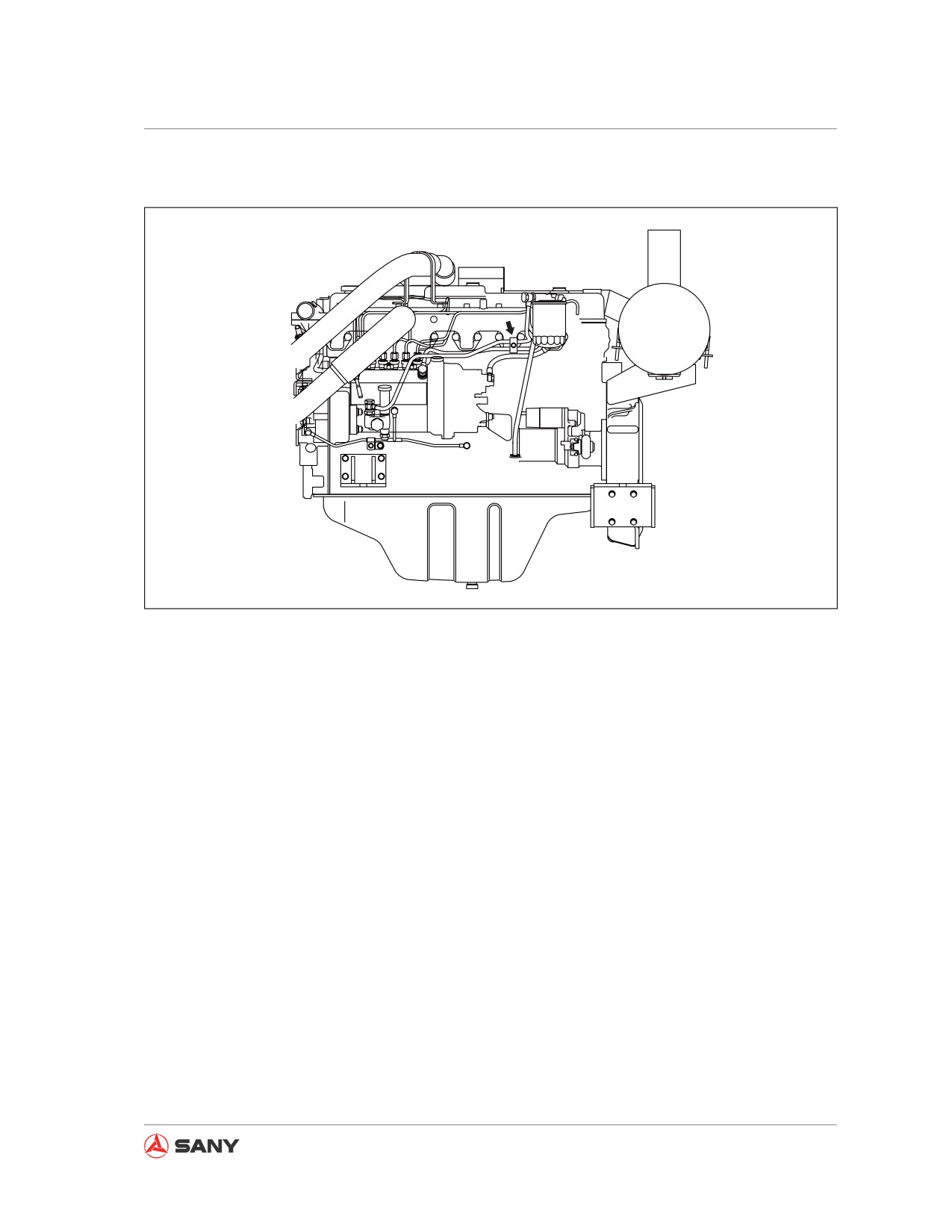
Check, through visual inspection and feel, for any loose bolts on the five mounting clamps of
high-pressure tubes between feed pump and injection nozzle. Check for any aged rubber. Con-
tact your Sany distributor to replace any part that fails.
5.8.9.5 Compressor working condition - inspect
The following two items are to be inspected:
1. Whether the compressor and the magnetic clutch are switched on/off when switching on/off
the air conditioner.
2. Whether the clutch or compressor produces abnormal noise.
In case of any problem, Contact your Sany distributor for disassembly, repair or replacement
of the parts.
5-97
Maintenance
5.8.10 Every 8000 service hours
Also perform maintenance for every 100, 250,
500, 1000, 2000 and 4000 service hours in the
meantime.
5.8.10.1 High-pressure tube clamps - re-
place
Contact your Sany distributor to replace the
high-pressure tube clamps on the engine.
5.8.11 Every 10000 service hours
Contact your Sany distributor for an overall
maintenance if your machine has worked for
10,000 hours.
5-98
Troubleshooting
Troubleshooting
6 Troubleshooting
6.1 Troubleshooting Preparation
6-3
6.1.1 Checks before troubleshooting
6-3
6.1.2 Troubleshooting procedure
6-4
6.1.3 Troubleshooting precautions
6-6
6.1.4 Electrical circuits troubleshooting precautions
6-9
6.1.5 Hydraulic components handling precautions
6-10
6.2 Pseudo Failures
6-12
6.3 Towing the Machine
6-13
6.4 Towing Hook for Light Loads
6-15
6.5 Severe Operating Conditions
6-15
6.6 Engine Failures
6-16
6.6.1 Engine troubleshooting table
6-16
6.6.2 Coolant temperature high
6-19
6.6.3 Engine oil pressure low
6-20
6.6.4 When fuel exhausts
6-22
6.6.5 When engine rotates reversely
6-24
6.7 Failures of the Electrical System
6-25
6.7.1 Electrical system troubleshooting table
6-25
6.7.2 Failure codes
6-28
6.8 Battery
6-30
6.8.1 Battery removal and installation
6-30
6.8.2 Battery charging
6-31
6.8.3 Jump-starting the engine
6-32
6.8.3.1 Connecting the jumper cables
6-33
6.8.3.2 Starting the engine
6-34
6-1
Troubleshooting
6.8.3.3 Disconnecting the jumper cables
6-34
6.9 Failures of the Hydraulic System
6-35
6.10 Other Common Failures
6-39
6-2

Troubleshooting
6 TROUBLESHOOTING
6.1 Troubleshooting Preparation
6.1.1 Checks before troubleshooting
Item
Judgement value
Remedy
1. Check fuel level and type of fuel
—
Add fuel
2. Check for impurities in fuel
—
Clean, drain
3. Check hydraulic oil level
—
Add oil
4. Check hydraulic oil strainer
—
Clean, drain
Lubricating
5. Check swing drive oil level
—
Add oil
oil, coolant
6. Check engine oil level (in oil pan)
—
Add oil
7. Check coolant level
—
Add water
8. Check dust indicator for clogging
—
Clean or replace
9. Check hydraulic filter
—
Replace
10. Check final drive oil level
—
Add oil
—
1. Check for looseness and corrosion of battery termi-
Tighten or replace
nal and wiring
—
Electrical
2. Check for looseness and corrosion of alternator ter-
Tighten or replace
equipment
minal and wiring
—
3. Check for looseness and corrosion of start motor
Tighten or replace
terminal and wiring
Hydraulic,
1. Check for abnormal noise and smell
—
Repair
mechanical
2. Check for oil leakage
—
Repair
equipment
3. Carry out air bleeding
—
Bleed air
1. Check battery voltage (engine stopped)
20-30V
Replace
2. Check battery electrolyte level
—
Add or replace
3. Check for discolored, burnt, exposed wiring
—
Replace
4. Check for missing wiring clamps and hanging wiring
—
Repair
5. Check for water leaking on wiring (be particularly
—
Electrics,
Disconnect con-
careful attention to water leaking on connectors or
electrical
nector and dry
terminals)
equipment
6. Check for blown or corroded fuses
—
Replace
7. Check alternator voltage (engine running at 1/2
After running for
Replace
several minutes:
throttle or above)
27.5~ 29.5V
8. Check operating sound of battery relay
—
Replace
(when switch is turned ON/OFF)
Table 6-1
6-3
Troubleshooting
6.1.2 Troubleshooting procedure
1.
Check and determine failure symptom.
Ask for the following information upon ser-
vice request of a client.
● Name of client
● Model and serial number of machine
● Detailed information on job site, etc.
Obtain general information through ques-
tions.
● Failure encountered
● Working condition when failure occurs
● Working environment
● Repair and maintenance history
2.
Determine possible locations of failure.
Refer to Troubleshooting Section in this
manual in order to find possible locations
of the failure.
3.
Prepare tools for troubleshooting.
Tools required:
● T-connector
● Hydraulic gauge, etc.
● Refer to the Parts Book and prepare
necessary replacement parts.
4.
Go to job site.
5.
Ask operator for more information on the
failure.
● Is there any abnormality before the fail-
ure occurred?
● Does the failure occurred suddenly?
6-4
Troubleshooting
● Did you do any repair when the failure
occurred?
6.
Play back the failure.
7.
Start the engine and operate the machine
to make sure that the symptom does exist.
Simply determine location of failure and
make repair before performing trouble-
shooting.
● Checks before starting
● Other checking items
Refer to Troubleshooting Section in this
manual and choose troubleshooting pro-
cedure according to machine symptom be-
fore performing the service work.
8.
Work out a service plan.
● Repair in work shop.
● Repair on job site.
6-5
Troubleshooting
6.1.3 Troubleshooting precautions
WARNING
Observe the following items before per-
forming any troubleshooting operations.
Failure to do so can cause machine dam-
age, personal injury or death.
●
Park your machine on a hard, level
ground. Make sure that the safety pins,
blocks and machine brake are effective.
●
Co-workers must use the same signal
system. Keep irrelevant people a safe
distance from the machine.
●
If the radiator cap is removed when the
engine is hot. Hot coolant may squirt
out and cause burns, wait for the engine
to cool down before troubleshooting.
●
Take care not to touch any hot parts or
be caught by any rotating parts.
●
Before disconnecting any electrical wir-
ing, always disconnect the negative (-)
post of battery.
●
Before removing the plug or cap from
any vessel that contains pressurized
oil, water or air, release the internal
pressure. When installing a measuring
equipment, be sure to connect it prop-
erly.
The aim of troubleshooting is to pinpoint the
basic cause of the failure, to carry out repairs
swiftly, and to prevent reoccurrence of the fail-
ure.
When carrying out troubleshooting, it is impor-
tant to understand the structure and function.
However, a short cut to effective troubleshoot-
ing is to ask the operator various questions
to form some idea of possible causes of the
failure that would produce the reported symp-
6-6
Troubleshooting
toms.
1.
When carrying out troubleshooting, do not
hurry to disassemble the components.
If components are disassembled immedi-
ately any failure occurs:
★ Parts that have no connection with the
failure or other unnecessary parts will
be disassembled.
★ It will become impossible to find the
cause of the failure.
It will also cause a waste of man-hours,
parts, or oil or grease, and at the same
time, will also lose the confidence of the
user or operator.
For this reason, when carrying out trouble-
shooting, it is necessary to carry out thor-
ough prior investigation and to carry out
troubleshooting in accordance with the
fixed procedure.
2.
Points to ask user or operator:
1) Have any other problems occurred
apart from the problem that has been
reported?
2) Was there anything strange about the
machine before the failure occurred?
3) Did the failure occur suddenly, or were
there problems with the machine condi-
tion before this?
4) Under what conditions did the failure
occur?
5) Had any repairs been carried out before
the failure? When were these repairs
carried out?
6-7
Troubleshooting
6) Has the same kind of failure occurred
before?
3.
Check before troubleshooting
1) Check the oil level.
2) Check for any external leakage of oil
from the piping or hydraulic equipment.
3) Check the travel of the control levers.
4) Check the stroke of the control valve
spool.
5) O t h e r m a i n t e n a n c e i t e m s c a n b e
checked externally, so check any item
that is considered to be necessary.
4.
Confirming failure
★ Confirm the extent of the failure your-
self, and judge whether to handle it as
a real failure or as a problem with the
method of operation, etc.
★ When operating the machine to reenact
the troubleshooting symptoms, do not
carry out any investigation or measure-
ment that may make the problem worse.
5.
Troubleshooting
★ Use the results of the investigation
and inspection in Items 2 - 4 to narrow
down the causes of failure, then use the
troubleshooting flowchart to locate the
position of the failure exactly.
★ The basic procedure for troubleshooting
is as follows.
1) Start from the simple points.
2) Start from the most likely points.
6-8
Troubleshooting
3) Investigate other related parts or
information.
6. Measures to remove root cause of failure
★ Even if the failure is repaired, if the root
cause of the failure is not repaired, the
same failure will occur again. To prevent
this, always investigate why the problem
occurred. Then, remove the root cause.
6.1.4 Electrical circuits troubleshooting
precautions
1. Always turn the power off before discon-
necting or connect connectors.
2. Before carrying out troubleshooting, check
that all the related connectors are properly
inserted.
★ Disconnect and connect the related con-
nectors several times to check.
3. Always connect any disconnected connec-
tors before going on to the next step.
★ If the power is turned ON with the con-
nectors still disconnected, unnecessary
abnormality displays will be generated.
4. When carrying out troubleshooting of
circuits (measuring the voltage, resistance,
continuity, or current), move the related
wiring and connectors several times and
check that there is no change in the read-
ing of the tester.
★ If there is any change, there is probably
defective contact in that circuit.
6-9
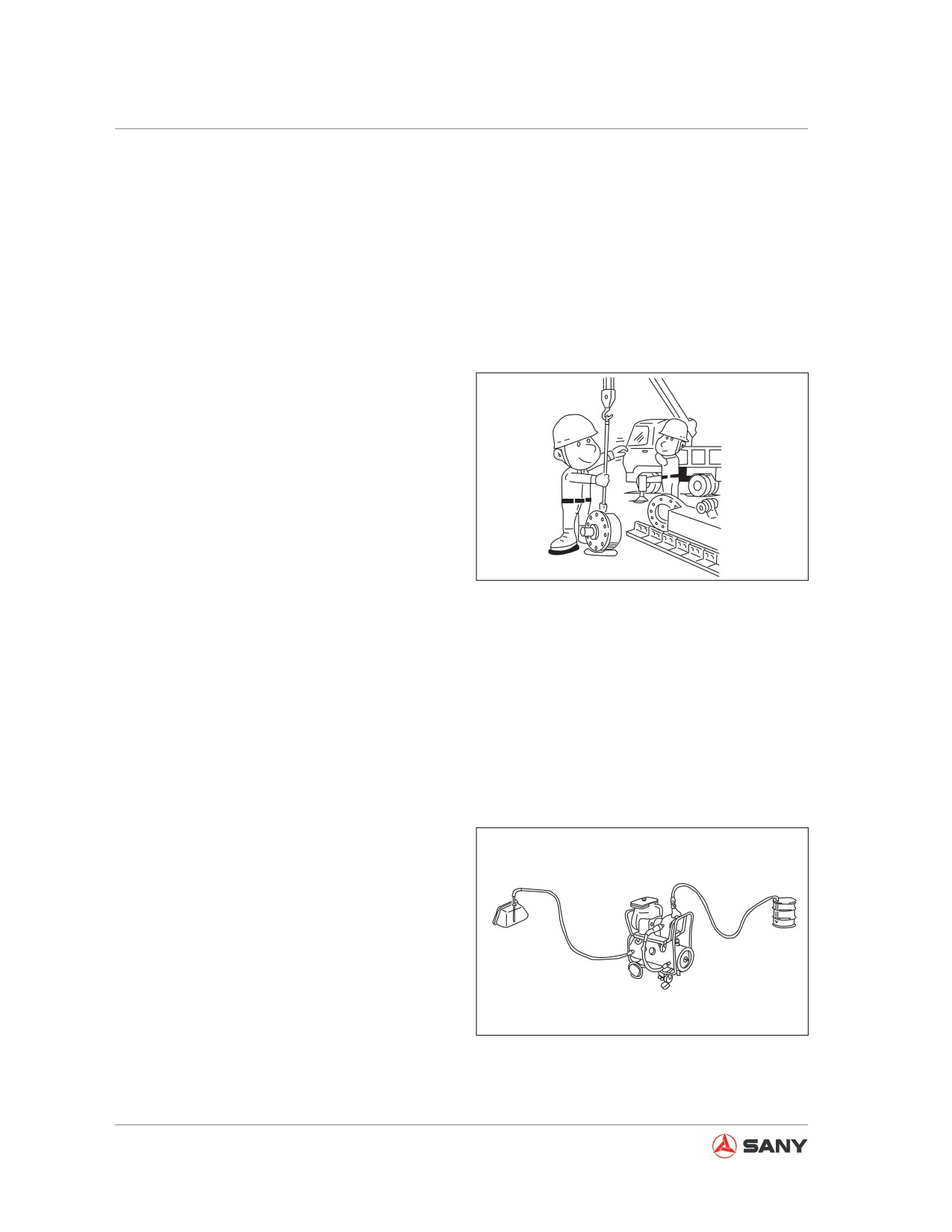
Troubleshooting
6.1.5 Hydraulic components handling precautions
With the increase in pressure and precision
of hydraulic equipment, the most common
cause of failure is dirt (foreign material) in the
hydraulic circuit. When adding hydraulic oil, or
when disassembling or assembling hydraulic
equipment, it is necessary to be particularly
careful.
1.
Be careful of the operating environment
Avoid adding hydraulic oil, replacing filters,
or repairing the machine in rain or high
winds, or places where there is a lot of
dust.
2.
Disassembly and maintenance work in the
field
ZX215-1000023
If disassembly or maintenance work is
Fig. 6-1
carried out on hydraulic equipment in the
field, there is danger of dust entering the
equipment. It is also difficult to confirm the
performance after repairs, so it is desir-
able to use unit exchange. Disassembly
and maintenance of hydraulic equipment
should be carried out in a specially pre-
pared dust-proof workshop, and the per-
formance should be confirmed with special
test equipment.
3.
Do not let any dirt or dust get in during
refilling operations.
Be careful not to let any dirt or dust get
in when refilling with hydraulic oil. Always
keep the oil filler and the area around it
clean, and also use clean pumps and oil
containers. If an oil cleaning device is
used, it is possible to filter out the dirt that
has been collected during storage, so this
ZX215-1000025
is an even more effective method.
Fig. 6-2
6-10