SANY Crawler Hydraulic Excavator SY115C9, SY135C8, SY135C9, SY155H. Safety, Operation and Manitenance Manual - page 7
Operation
4.17.3 After storage
Note:
If your machine has been stored for a long pe-
riod but no rusting prevention had been made
each month, please contact Sany distributor
before operating your machine again.
Before using your machine again after a long-
term storage, perform as described below:
● Wipe off the grease from the piston rod of
hydraulic cylinder.
● Apply lubricant or grease to all necessary
locations.
● The moisture of air can mix with oils when
your machine has been stored for a long
time. Check the oils before and after start-
ing the engine. If the oil contains water, re-
move the water timely.
4.17.4 Starting the engine after long-
term storage
Before starting a machine that has been
stored for a long period of time, it is important
to fully warm up the engine.
For more information see “Warm-up opera-
tion” on page 4-26.
4-56
Operation
4.18 Transportation Information
Related laws and regulations must be ob-
served when transporting the machine. Safety
must be ensured.
4.18.1 Transport methods
● Choose a method that is suitable for the
weight and dimension provided in the
section“Specification”.
● The weight and dimension provided in
"Specification" can vary due to different
type of track shoe, arm or other additional
equipment.
● For transport of the machine installed with
cab protection housing, please contact
Sany distributor for more information.
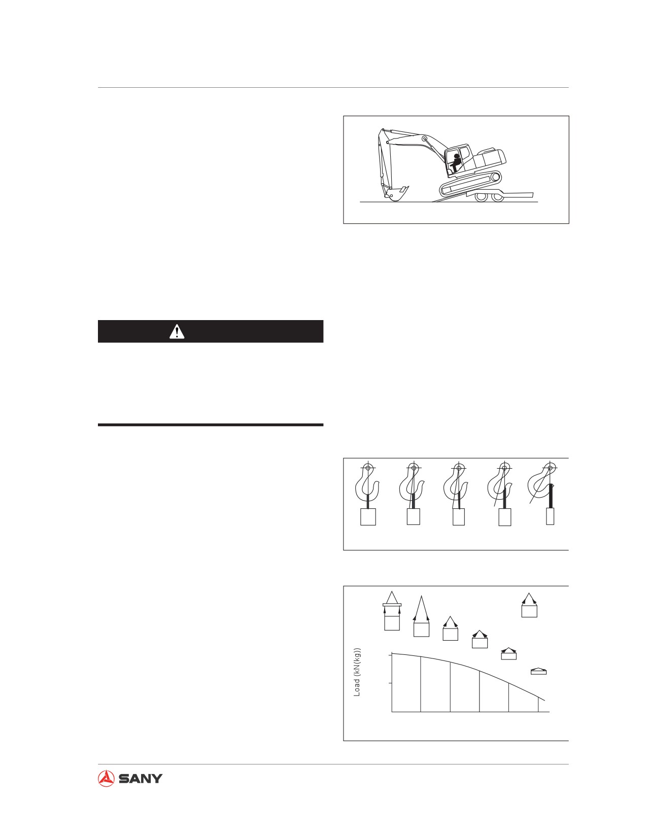
4.18.2 Loading/unloading machine to/
from a trailer
The following instruction must be followed
when loading/unloading the machine.
● Choose a hard, level ground to load and
unload your machine. Keep a safe dis-
tance to sides of road.
● Auto idle must be switched off. If the auto
idle switch is activated, the machine may
move suddenly.
● The travel speed must be set to low (Lo).
Run the engine at idle speed and operate
CZ335-1103227
your machine slowly when loading or un-
loading.
Fig.
4-97
● In a cold region, it is important to fully pre-
heat your machine and ensure a stable
rpm of the engine before loading or un-
loading.
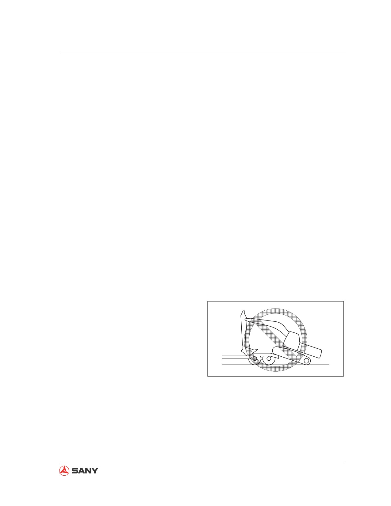
● Never reposition your machine on the ac-
cess ramp, which may otherwise cause
your machine to tip over. If necessary, re-
position your machine on a level ground or
4-57
Operation
on the trailer.
●
It is dangerous to load or unload your ma-
chine with the work equipment. The use of
an access ramp is necessary.
●
On an access ramp, never maneuver any
other control lever except the travel control
lever.
CZ335-1103228
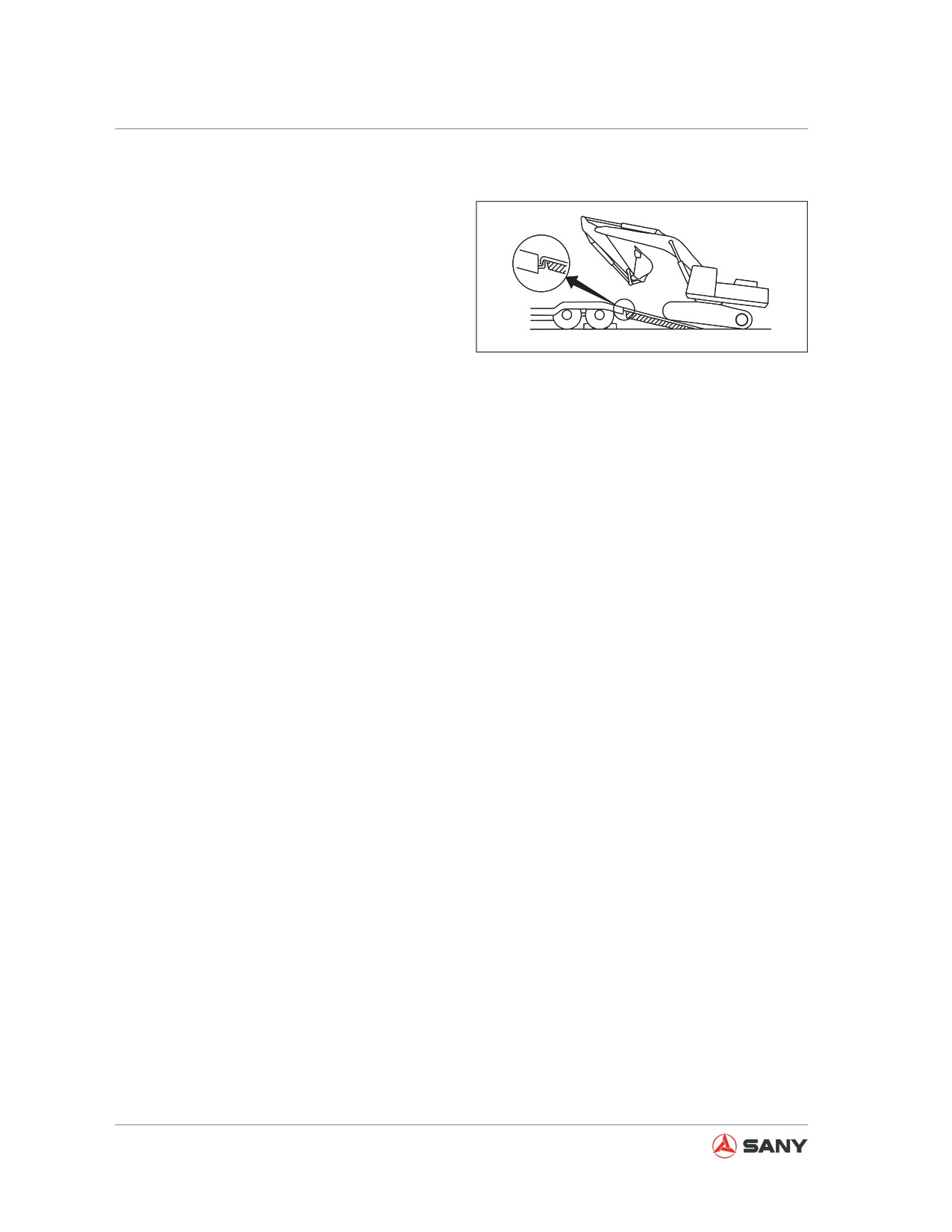
●
At the junction of the access ramp and
trailer, the machine's center of gravity may
Fig. 4-98
change suddenly and it is possible to loose
balance. Drive slowly when passing the
junction.
●
If you have to swing the work equipment
on the trailer, be extra careful with your
machine, which may tip over due to insta-
ble base.
If the work equipment has been installed
on the machine, it must be retracted slowly
to avoid the machine loosing balance.
●
Considering operating safety, a signal man
shall be assigned to alert preventing the
machine from falling off the ramp.
The following items must be carefully ob-
served:
● Use an access ramp with enough width,
length, thickness and strength. Ramp
grade shall not exceed 15°.
● When piling the earth to build a platform,
the platform must be fully compacted to
prevent landslide.
● To prevent the machine from skidding
on the ramp, clean its track shoes and
the ramp before loading and unloading.
The machine has the danger to skid when
the access ramp is contaminated with wa-
ter, snow, grease or ice.
4-58
Operation
4.18.2.1 Loading the machine
1. The machine shall only be loaded and
unloaded on a hard, level ground.
It is necessary to keep a safe distance to
roadside.
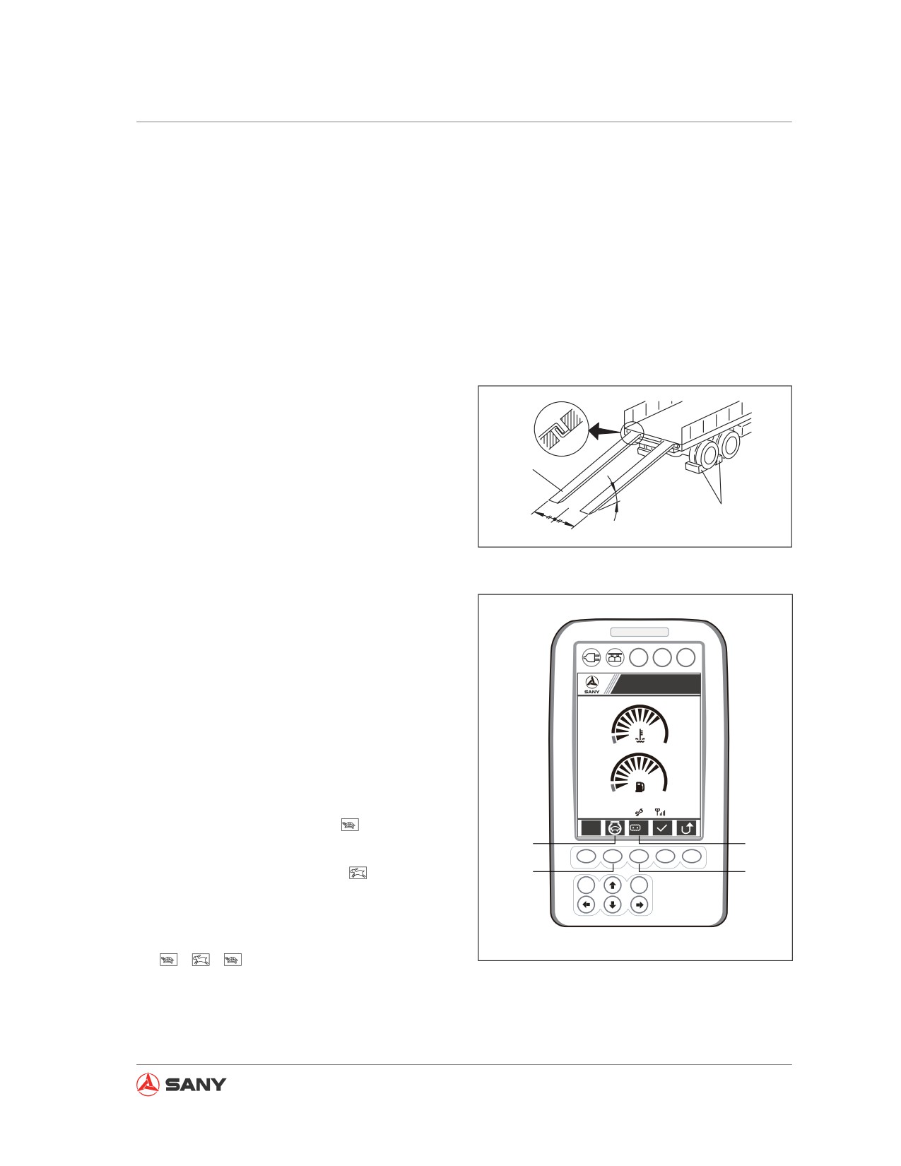
2. Choke the trailer and put blocks under its
wheels to prevent its moving.
Use two access ramps (2) and place them
at the left and right sides respectively. The
two ramps shall parallel each other and
have equal distance to trailer centerline (3).
Ramp grade (4) shall not exceed 15°. If the
2
ramps bend too much under the weight of
machine, supports must be placed under
1
the ramps to prevent their bending.
4
3
CZ335-1103229
Fig. 4-99
3.
Set the travel speed selector switch to low
speed (Lo).
●
Press travel speed button
(6) to change
A
B
C
travel speed (Lo, Hi), which will be dis-
Sany Hydraulic Excavator
played at (5) on the display screen.
S
1
4.
Press button (8) to turn off auto decelera-
tion. Use the fuel control dial to set engine
speed to low idle.
●
When machine is running in auto idle
09/03/05
0000h 00m
12
12:25:31
mode, the screen displays
at (7).
S
Lo
7
5
●
Press the button (8) again to cancel auto
F1
F2
F3
F4
F5
idle. The screen will display
at (5).
8
6
ESC
Enter
●
Auto idle is the default mode after the ma-
chine is started. Press the button (8) to
toggle between auto-idle and non auto-idle
CZ135-1103006
→
→
Fig. 4-100
4-59
Operation
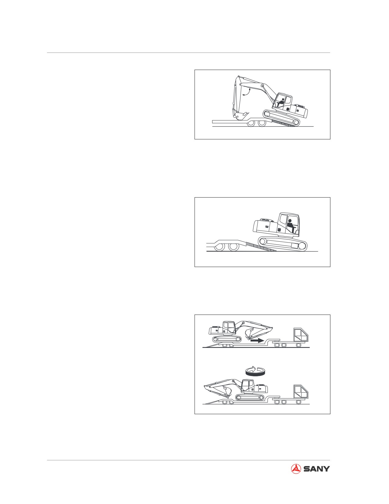
5. If the machine is installed with work equip-
ment, the work equipment must be placed
in front of the machine. Move the machine
straight forward up the ramp. Without the
90°-110°
work equipment, reverse the machine up
the ramp.
Lower the bucket on the trailer to sup-
CZ335-1103231
port the machine immediately after getting
aboard.
Fig. 4-101
Instruction and signals from a commander
must be followed, in especially reverse
travel.
6. Align your machine with the ramp before
driving up the ramp. The centerline of ma-
chine shall match the centerline of trailer.
Align your machine with the ramp and trav-
el slowly.
Lower the work equipment as low as pos-
CZ335-1103232
sible if it causes no trouble.
Fig. 4-102
On an access ramp, only the travel lever
can be maneuvered. Never maneuver any
other control levers.
7. Drive the machine slowly forward till all
tracks are on the trailer and have full
contact with trailer floor.
8. When the machine passes the rear wheels
of the trailer, the machine could lean
forward. So drive the machine slowly and
carefully in order to avoid impact with the
trailer.
9. Slightly raise the bucket, retract the arm
and maintain it in lower position, and slowly
CZ335-1103233
swing the upper structure by 180°.
Fig. 4-103
4-60
Operation
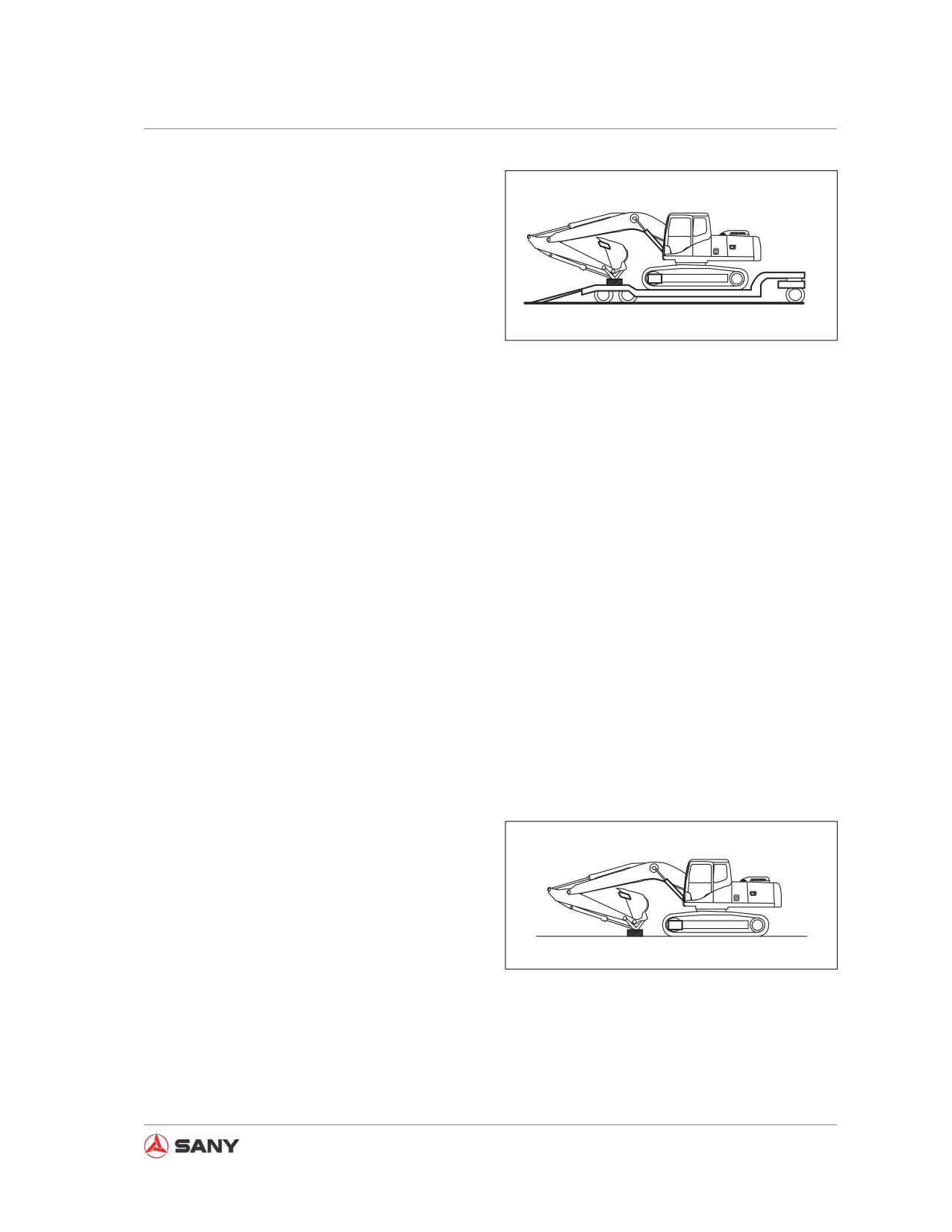
10. Fully extend the bucket cylinder and arm
cylinder, and slowly lower the boom.
11. Place a wood block under the end of the
bucket cylinder in order to prevent it from
touching the trailer floor, which could result
in damage to the cylinder.
CZ335-1103234
Fig. 4-104
4.18.2.2 Securing the machine
Note:
● Reinstall the rear view mirrors in order to
enable them to be within the sphere of ma-
chine width.
● To prevent damage to the bucket cylinder
during transit, place a wood block under
the top end of the bucket linkage so as to
prevent the bucket cylinder from touching
the trailer floor.
● Check if the engine hood is locked. Seize
the grip of engine hood and lift it slightly.
If it is not open, it indicates that the hood
catch is engaged. If the hood is not locked,
it might be swung open during transit.
Secure the machine to the trailer through the
following steps:
1. Fully extend the bucket cylinder and arm
cylinder, and slowly lower the boom.
CZ335-1103235
Fig. 4-105
4-61
Operation
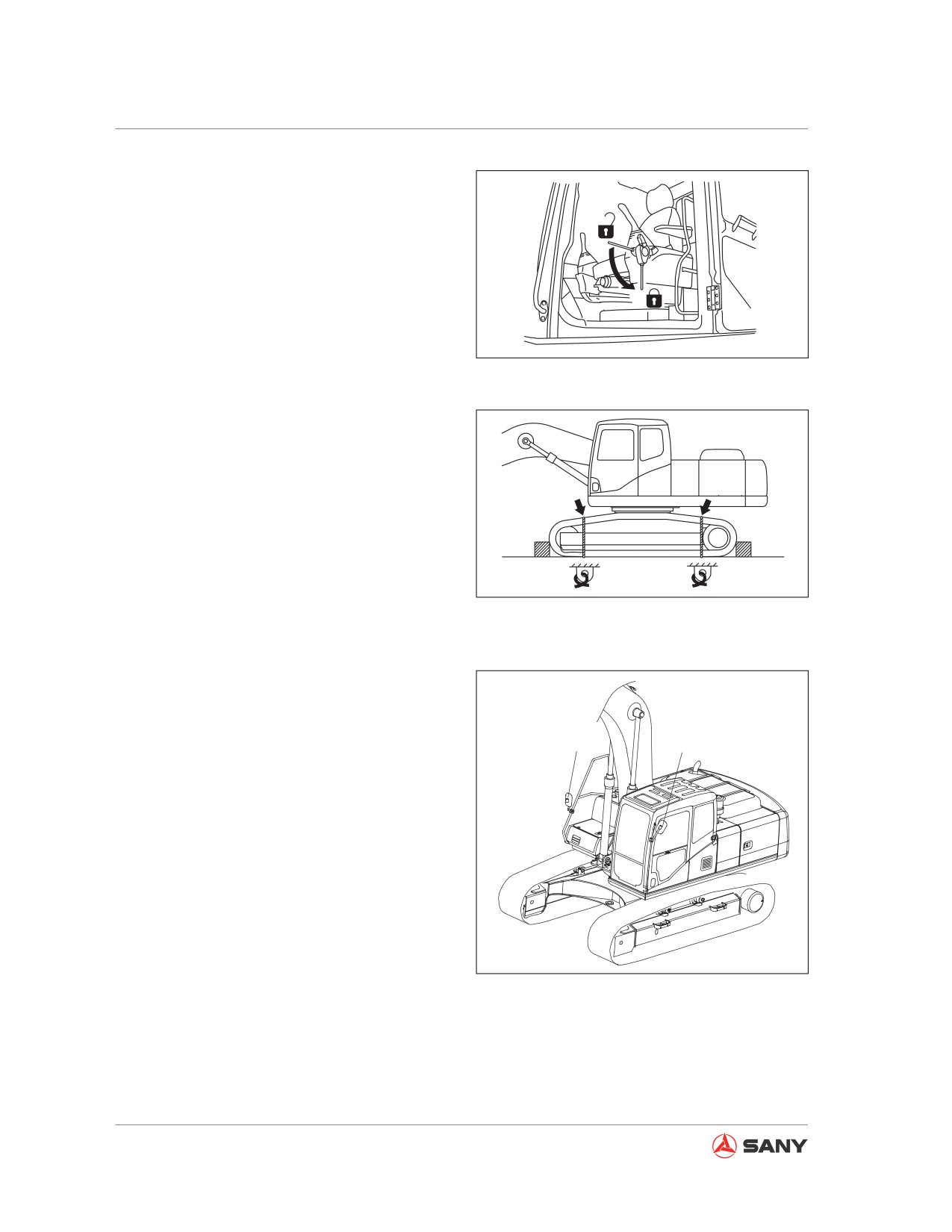
2.
Place the hydraulic lockout control to the
LOCK position (L).
F
3.
Stop the engine and remove the key from
the start switch.
4.
Close all doors, windows and covers
L
properly.
CZ335-1103251
Lock the covers, caps and doors.
Fig. 4-106
5.
Chock the tracks on both ends in order to
prevent the machine from moving during
transportation. Tie down the machine
with chains or wire ropes with sufficient
strength.
It is important to keep the machine in a
proper position in order to ensure that the
machine could not slip to the sides.
CZ335-1103237
Fig. 4-107
4.18.2.3 Rear view mirrors
The rear view mirror is located in the position
B
A
shown in the right illustration.
● If the rear view mirror is broken or it is nec-
essary to reinstall the mirror after disas-
sembling for shipping purpose, the follow-
ing procedure must be observed.
● The rear view mirror must be readjusted
after installation. For more information
see“Rear view mirrors” on page 4-17.
CZ335-1103238
Fig. 4-108
4-62
Operation
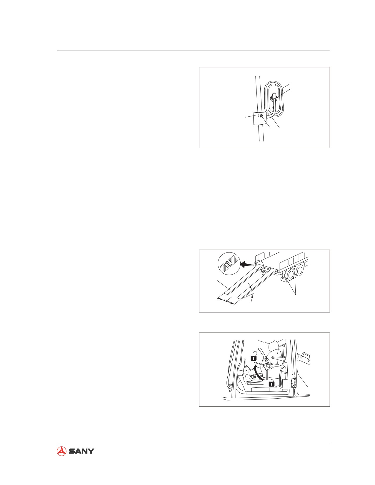
Removal
1
1. Loosen bolt (2) and remove the rear view
2
mirror (1) from the bar (3).
2. Loosen bolt (4) and remove the bar (3) and
the clasp (5).
5
4
3
CZ335-1103239
Fig. 4-109
Installation
1. Install the bar (3) and the clasp (5) to the
handhold, and tighten bolt (4).
2. Install the rear view mirror (1) to the bar (3),
and tighten the bolt (2).
4.18.2.4 Unloading the machine
1.
Load and unload the machine only on
a hard, level ground, and keep a safe
distance from roadside as well.
2
2.
Apply braking to the trailer and chock the
trailer under its wheels to prevent moving.
1
4
3
CZ335-1103240
Use two access ramps (2) and place them
at the left and right sides respectively. The
Fig.
4-110
two ramps shall parallel each other and
have equal distance to trailer centerline (3).
Ramp grade (4) shall not exceed 15°. If the
ramps bend too much under the weight of
F
machine, supports must be placed under
the ramps to prevent their bending.
3.
Remove the chains and wire ropes fasten-
L
ing the machine.
CZ335-1103236
4.
Start the engine and warm it up fully.
Fig.
4-111
5.
Move the hydraulic lockout control to FREE
position (F).
4-63
Operation
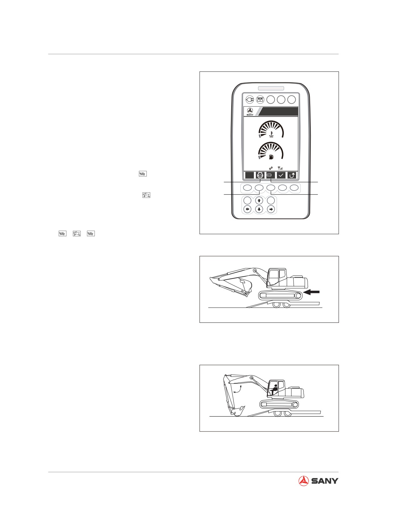
6.
Set the travel speed selector switch to low
speed (Lo).
●
Press travel speed button
(6) to change
A B C
travel speed (Lo, Hi), which will be dis-
Sany Hydraulic Excavator
played at (5) on the display screen.
S
1
7.
Press button (8) to turn off auto decelera-
tion. Use the fuel control dial to set engine
speed to low idle.
●
When machine is running in auto idle
09/03/05
0000h 00m
12
12:25:31
mode, the screen displays
at (7).
S
Lo
7
5
●
Press the button (8) again to cancel auto
F1
F2
F3
F4
F5
idle. The screen will display
at (5).
8
6
ESC
Enter
●
Auto idle is the default mode after the ma-
chine is started. Press the button (8) to
toggle between auto-idle and non auto-idle
CZ135-1103006
→
→
Fig. 4-112
8.
Raise the work equipment, retract the arm
below the boom, and drive the machine
slowly.
9.
Stop the machine when it comes to the
rear wheels of the trailer and is positioned
horizontally.
CZ335-1103242
Fig. 4-113
Remark:
● Make sure to keep an angle of 90 - 110°
between the arm and the boom when un-
loading the machine.
90°-110°
● The machine could be damaged if it is un-
loaded with retracted arm.
When the machine runs on the access
ramp, never penetrate the bucket into
CZ335-1103243
ground, which could damage the hy-
Fig. 4-114
draulic cylinder.
10. While the machine is on the ramp, it is
4-64
Operation
important to keep an angle of 90 - 110°
between the arm and the boom. Lower
the bucket to the ground and move the
machine slowly.
11. When the machine is going down the
ramp, slowly operate the boom and arm,
CZ335-1103244
and carefully drive the machine off the
ramp.
Fig. 4-115
4.18.3 Lifting the machine or its com-
ponents
WARNING
Using a single rope to lift an object is pos-
sible to cause turning of the load and un-
fastening or slipping of the rope. Serious
accidents could result.
4.18.3.1 Lifting precautions
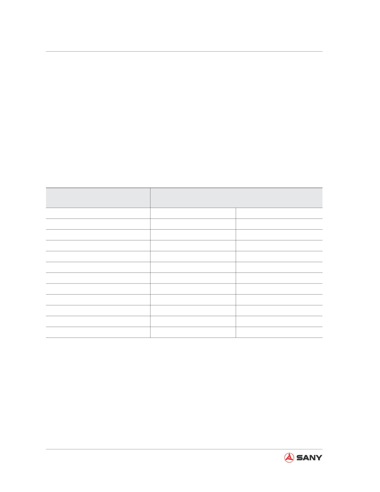
1. Put wire rope on the middle of hook.
If wire rope is hooked near hook end, the
rope may slide off the hook, causing seri-
100%
88%
79%
71%
41%
ZX215-1000002
ous accident. The middle part of hook is
stronger than the rest parts.
Fig. 4-116
2. Never lift an object when wire rope forms
a bigger sling angle with the hook. If two
or more ropes are used, the load on each
kN
rope increases with sling angle. The fol-
(kg)
19.6
lowing table shows variation of allowable
(2000)
18.6
16.7
(1900)
(1700)
13.7
load kN(kg) with different angles when
19.6
(1400)
(2000)
9.8
two ropes are used to lift a load. If a single
(1000)
4.9
rope is capable of lifting 9.8 kN(1000 kg)
9.8
(500)
(1000)
in vertical position, two ropes will be able
to lift
19.6 kN(1000 kg) perpendicularly.
30
60
90
120
150
However, when the two ropes forms a sling
Lifting angle (°)
ZX215-1000001
angle of 120 degrees, its lifting capacity
becomes 9.8 kN(1000 kg). On the other Fig. 4-117
4-65
Operation
hand, if the sling angle is 150 degrees, to lift a load of 19.6 kN(1000 kg), each rope has to
bear 39.2 kN(1000 kg).
3. Never use a single rope to lift an object. It’s better to bind the object with two or more rope
symmetrically.
4.18.3.2 Choosing a wire rope
Select a suitable wire rope according to the object to be lifted. See the table below.
Wire Rope
(Standard bright wire rope “Z”)
(JISG3525,No.6,6X37-A type)
Wire Rope
Allowable Load
Nominal Diameter
mm
kN
Ton
10
8.8
0.9
12
12.7
1.3
14
17.3
1.7
16
22.6
2.3
18
28.6
2.9
20
35.3
3.6
25
55.3
5.6
30
79.6
8.1
40
141.6
14.4
50
221.6
22.6
60
318.3
32.4
Table
4-1
Note:
The allowable load equals to one sixth of the breaking force of wire rope. (Safety factor: 6)
4-66
Operation
4.18.3.3 Lifting the machine
WARNING
● Only eligible, experienced operator with official license (according to local laws) is al-
lowed to operate a crane.
● Never lift the machine when someone is riding on it.
● Nobody shall be allowed to enter the area below or around the lifted machine.
● Make sure that the wire cables used for lifting the machine are strong enough to bear
the weight of machine. Never use damaged or aged wire cable or sling.
● Never lift the machine when its upper structure has swung aside. Before lifting, it is
important to move the work equipment to the final drive end and keep the longitudinal
centerlines of the upper structure and the lower structure parallel.
● Before lifting, the lockout control must be put to "locked" position in order to prevent
unexpected movement of the machine.
● Keep the machine parallel to the ground during lifting.
● Never lift the machine at fast speed, which may otherwise overload the wire cables or
slings and result in rupture.
Besides the attitudes recommended in the following procedure, never use any other at-
titudes to lift the machine. Never use the type of lifting equipment other than the ones
specified in the following procedure. Otherwise it may have the danger to loose balance.
Note:
The lifting procedure is applicable to machines of standard dimension.
The lifting methods may vary according to actual additional and optional components installed.
Contact Sany distributor for suitable lifting methods.
For more information on the weight of machine see the section "Specification".
When lifting the machine, operate on a level ground according to the following steps.
4-67
Operation
Machine of standard dimension
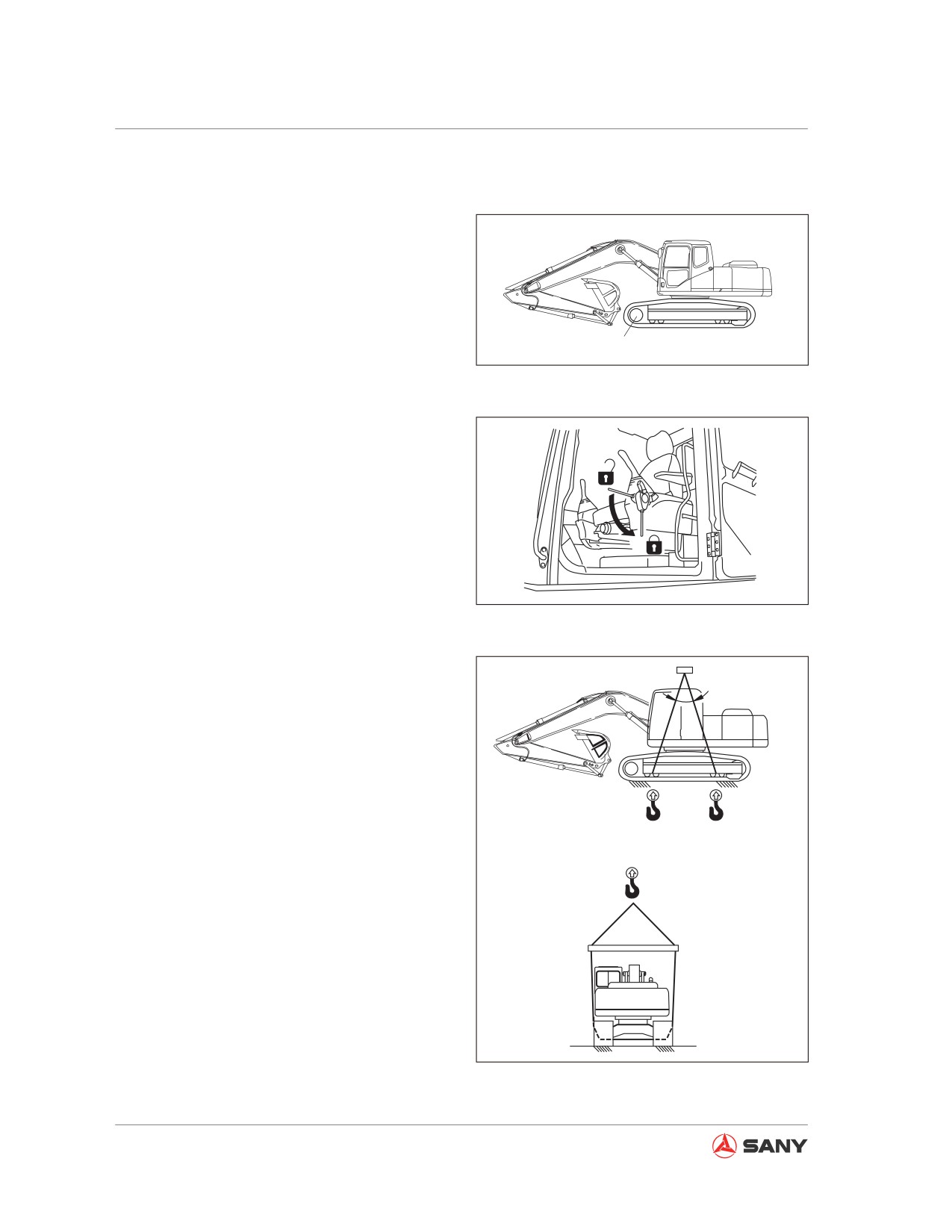
1.
Start the engine and swing the upper
structure in order to position the work
equipment at the side of the sprocket (1).
2.
Fully extend the bucket cylinder and the
arm cylinder, and use the boom cylinder to
lower the work equipment to the ground,
1
CZ335-1103245
as shown in the right illustration.
Fig. 4-118
3.
Move the hydraulic lockout control to
"locked" position (L).
F
4.
Shut off the engine. Check the surrounding
of the cab before leaving the machine.
Close the cab door and windows properly.
L
CZ335-1103251
Fig. 4-119
5.
Run a wire rope between the first two track
rollers and between the last two track
A
rollers. For machines installed with roller
guard, the ropes shall go through under
the tracks.
6.
Adjust the wire rope lifting angle (A) to 30 -
40°, and lift the machine slowly.
7.
When the machine is above the ground,
make sure that the hook condition and
the lifting condition are normal, and lift the
machine slowly.
CZ335-1103246
Fig. 4-120
4-68
Maintenance
Maintenance
5 Maintenance
5.1 Maintenance Information
5-5
5.2 General Service
5-9
5.2.1 Oil, fuel and coolant
5-9
5.2.1.1 Oil
5-9
5.2.1.2 Fuel
5-10
5.2.1.3 Coolant
5-11
5.2.2 Grease
5-12
5.2.3 Oil and fuel storage
5-13
5.2.4 Filter element
5-13
5.2.5 Electrical system
5-14
5.2.6 Hydraulic system
5-14
5.3 Replacement Parts
5-16
5.4 Recommended Fluids
5-17
5.4.1 Fluid capacities
5-19
5.4.2 Recommended oils:
5-20
5.5 Tightening Torque Specification
5-22
5.6 Safety-Related Parts
5-24
5.7 Maintenance Schedule
5-25
5.7.1 List of maintenance schedule
5-25
5.7.2 Hydraulic Breaker Service Interval
5-27
5.8 Maintenance Procedures
5-28
5.8.1 Maintenance after initial 50 service hours
5-28
5.8.1.1 Engine oil and filter - change/replace
5-28
5.8.1.2 Fuel filter - replace
5-28
5.8.2 When Required
5-29
5-1
Maintenance
5.8.2.1 Air cleaner - clean/replace
5-29
5.8.2.2 Cooling system - clean
5-37
5.8.2.3 Track shoe bolts - inspect/tighten
5-41
5.8.2.4 Track tension - inspect/adjust
5-42
5.8.2.5 Bucket tips (lateral pin) - replace
5-45
5.8.2.6 Bucket Replacement
5-47
5.8.2.7 Bucket clearance - adjust
5-49
5.8.2.8 Window washer fluid - check/refill
5-51
5.8.2.9 Air conditioner - inspect/service
5-52
5.8.2.10 Gas spring - inspect
5-54
5.8.2.11 Air in hydraulic system - purge
5-55
5.8.2.12 Hydraulic circuit internal pressure - release
5-58
5.8.3 Checks before starting
5-59
5.8.4 Every 100 service hours
5-60
5.8.4.1 Lubrication
5-60
5.8.5 Every 250 service hours
5-63
5.8.5.1 Compressor belt tension - inspect/adjust
5-63
5.8.5.2 Oil in engine oil pan and oil filter - change/replace
5-65
5.8.5.3 Primary fuel filter - replace
5-67
5.8.5.4 Secondary fuel filter - replace
5-71
5.8.6 Every 500 service hours
5-74
5.8.6.1 Swing bearing - lubricate
5-74
5.8.6.2 Swing pinion gear grease - check/refill
5-75
5.8.6.3 Coolant tank and radiator fins - inspect/clean
5-76
5.8.6.4 Air conditioner filters - clean
5-77
5.8.6.5 Swing drive oil - check/refill
5-80
5.8.6.6 Final drive oil - check/fill
5-81
5.8.7 Every 1000 service hours
5-82
5.8.7.1 Hydraulic oil filter - replace
5-82
5.8.7.2 Swing drive oil - change
5-84
5.8.7.3 Engine exhaust pipe clamps - check
5-85
5.8.7.4 Fan belt tension - check/replace
5-85
5.8.7.5 Nitrogen pressure in accumulator (breaker) - check
5-85
5.8.8 Every 2000 service hours
5-86
5.8.8.1 Final drive oil - change
5-86
5.8.8.2 Hydraulic tank filter screen - clean
5-88
5-2
Maintenance
5.8.8.3 Nitrogen pressure in accumulator (control oil circuit) - check
5-89
5.8.8.4 Hydraulic circuit internal pressure - release
5-92
5.8.8.5 Oil in hydraulic tank - change
5-93
5.8.8.6 Alternator - inspect
5-95
5.8.8.7 Engine valve clearance - check/adjust
5-95
5.8.9 Every 4000 service hours
5-95
5.8.9.1 Coolant pump - inspect
5-95
5.8.9.2 Start motor - check
5-95
5.8.9.3 Accumulator (control oil circuit) - replace
5-96
5.8.9.4 High-pressure tube clamps and rubber - check
5-97
5.8.9.5 Compressor working condition - inspect
5-97
5.8.10 Every 8000 service hours
5-98
5.8.10.1 High-pressure tube clamps - replace
5-98
5.8.11 Every 10000 service hours
5-98
5-3
Maintenance
5 MAINTENANCE
5.1 Maintenance Information
Never conduct any inspection and mainte-
nance work other than the scope specified in
this manual.
Hour meter reading
Keep track of the hour meter reading on a
daily basis. Make sure whether it is time to
perform the required maintenance.
Genuine Sany replacement parts
Always use genuine Sany replacement parts
listed in the Parts Manual.
Genuine Sany lubricants
Always use genuine Sany engine oil and
grease. Select engine oil and grease of suit-
able viscosity according to ambient tempera-
ture.
Window washer fluid
Use automotive windshield washer fluid only,
which shall not be contaminated by foreign
substances.
Oil and lubricants
Always use clean oils and greases. Keep the
oil reservoir and grease reservoir clean, which
shall be free from any impurities.
Drained oil and used filter element
After changing the oil and replacing the filter
element, check the used oil and filter element
for signs metal particles and foreign mate-
rial. If large amount of metal particles and/or
impurities are found in the used oil and filter
element, report to the personnel in charge and
take proper measures.
5-5
Maintenance
Primary fuel filter
Primary Fuel Filter must be installed before fill-
ing the fuel.
Welding instruction
● Turn off the engine start switch and wait for
1 minute before disconnecting the negative
(-) terminal of the battery.
● Connect the ground cable of the welder at
least 1 m (3.3 ft.) away from the place be-
ing welded.
● If the ground cable is connected to any
electrical components (instrument, con-
nector, etc.), the instrument will be out of
function. If there are any seals or bearings
between the weld and the grounding point,
choose another grounding point away from
these parts.
● Never use a grounding point in the vicinity
of the work equipment pin or hydraulic cyl-
inder .
● Never apply more than 200V continuously.
Preventing things from falling into machine
● When opening the access window or tank
filler for inspection, make sure that the
nuts, bolts or tools are not left inside the
machine. Failure to do so could result in
unexpected failure or damage to the ma-
chine, or accidents. In case that any mate-
rials fall into the machine, remove it imme-
diately.
● Never carry unnecessary items in your
pockets except those necessary for inspec-
tion.
Dusty work site
Observe the following items before working in
a dusty place.
● When inspecting your machine or chang-
ing the oil, park your machine in a dust-
5-6
Maintenance
free place in order to prevent dust from
getting into the oil.
● Clean the air filter cartridge immediately if
the filter's alarm indicates clogging.
● Clean the fins and other heat exchanger
parts frequently to avoid them being
clogged.
● Clean and replace the fuel filter frequently.
● Clean the electrical components, espe-
cially the start motor and the alternator, to
prevent dust from building up on them.
Lubricants of different brands
Never mix lubricants of different brands and/or
grades together. If you need to use the lubri-
cant of another brand or grade, drain the old
lubricant completely and replace with the new
brand.
Securing access cover
When servicing the machine with the access
covers open, use a locking lever to secure the
cover to certain position. Otherwise, the cover
can be swung close by wind and cause bodily
injury.
Purging air from hydraulic system
When any hydraulic units have been repaired
or replaced or any hydraulic lines have been
removed or installed, always bleed the air from
the system. For more information see "Air in
hydraulic system - purge."
Connecting hydraulic hoses
● In removal of parts with O-rings or gaskets,
clean the installation surfaces and replace
with new parts. Remember to install the O-
rings or gaskets.
● Never twist or bend the hydraulic hoses
when assembling. Failure to do so could
cause damage to the hoses and consider-
ably reduce their service life.
5-7
Maintenance
After inspection and maintenance
If no checks have been made after inspection
and maintenance, unexpected failure may oc-
cur, causing severe injury or damage. The fol-
lowing items must be observed:
●
Checks when machine is running.
● For more information on checks during
engine operation see "Maintenance dur-
ing Engine Running." Be alert to your
safety in the meantime.
● Whether the checked or maintained
parts work normally.
● Whether oil leakage occurs when the
engine speed increases and the oil is
under pressure.
●
Checks after the operation (when the en-
gine has been shut down)
● Whether you have missed the items to
be checked or maintained.
● Whether all the checks and mainte-
nance have been performed correctly.
● Whether any tools and parts are left in
the machine. It is very dangerous to
have a foreign object blocked in the link-
age.
● Whether leakage of water or oil occurs;
whether all the bolts have been screwed
tightly.
Closing engine hood properly
When the engine hood is closed after inspec-
tion and maintenance, hold the lever and lift
the engine hood slightly in order to check
whether the lock is securely engaged. An un-
locked hood may be opened and cause acci-
dents.
5-8
Maintenance
5.2 General Service
● Use genuine Sany replacement parts,
grease and oil.
● Never change or refill oil with a different
type. When different oil is to be used, the
used oil must be drained completely before
filling the fresh oil. Meanwhile, the oil filter
must be replaced. (A small amount of used
oil remaining in the lines would affect noth-
ing.)
● Unless specified otherwise, your machine
contains the following oils and coolants
when delivered from the factory.
Item
Type
Engine Oil Pan
Diesel Oil CH-4 15W-40
Swing Drive
Gear Oil 85W/140
Final Drive
Hydraulic System
Caltex HDZ46
Radiator
TEEC-L35 antifreeze
Table 5-1
5.2.1 Oil, fuel and coolant
5.2.1.1 Oil
● The oils in engine and hydraulic units keep
deteriorating when operating your machine
under extreme conditions, such as high
pressure and high temperature.
● Always use the type of oil recommended
in the "Maintenance Section", which shall
also be applicable under extreme ambient
temperatures.
● Within the specified oil change interval, the
oil must be changed even if it is not dirty.
● Like the blood in human body, lubricant
shall be handled carefully in order to pre-
vent impurities such as water, metal par-
ticles and dust.
5-9
Maintenance
●
Most troubles of the machine are caused
by impurities.
Pay special attention to the prevention of
any impurities when storing or filling the oil.
●
Fill the amount of oil as specified. Failure
to do so could result in abnormality.
●
Never mix oils of different grades or brands
together.
●
Contact your Sany distributor when the oil
in your work equipment has been contami-
nated by water or air.
●
To know the condition of your machine,
regular oil quality analysis is recommend-
ed. Contact your Sany distributor if you
need such service.
●
Related filter elements must be replaced
when changing the oil. In replacement of
engine oil filter element, acceptable clean
oil shall be filled into the new filter element
prior to installation.
●
Use the oils approved by Sany.
●
Never use the hydraulic oil that has not
been approved by Sany, which can block
filter cartridge.
●
Remove the remaining oil as much as pos-
sible from the lines and cylinders when
changing the hydraulic oil. A small amount
of different residual is acceptable.
5.2.1.2 Fuel
● To prevent the moisture in air from con-
densing in the fuel tank, the tank must be
fully refueled after each workday.
● The fuel injection pump is a precise com-
ponent, which may not work normally if the
fuel contains water or other foreign sub-
stances.
● The sediment and water in the fuel tank
must be drained before starting the engine
or after 10 minutes since injection of oil.
5-10
Maintenance
● Flush the fuel tank and the fuel system
in case of any impurities found in the fuel
tank.
● The air in fuel path must be eliminated in
case that the engine runs out of fuel or the
filter cartridge has been replaced.
● Always use the type of fuel specified in the
"Maintenance Section."
● The fuel can freeze below the speci-
fied temperature (especially lower than
-15°C (5°F)).
● When the fuel is used above the speci-
fied temperature, its viscosity and out-
put power will decrease .
● Pay special attention to prevention of
impurities when storing or refilling the
fuel.
Note:
Always use diesel oil as the fuel.
To ensure favorable consumption and exhaust
of the fuel, the engine installed to your ma-
chine uses high-pressure oil injection unit with
mechanical control. The unit contains high-
precision components that require high-quality
lubrication. Therefore, the use of low-viscosity
fuel with low lubricating capability will consid-
erably reduce the service life of the unit.
5.2.1.3 Coolant
● The coolant is also an important fluid
against corrosion and freezing.
Anti-freezing coolant is also necessary in
regions where freezing prevention is un-
necessary.
Sany machines are prefilled with TEEC-
L35 antifreeze, which has excellent perfor-
mance in anticorrosion, anti-freezing and
cooling, and can last for 1 year or 2000
5-11
Maintenance
hours.
As a basic principle, we do not recommend
you using coolants other than TEEC-L35
antifreeze. The use of other coolants is
possible to cause serious problems, such
as corrosion of the light metal parts of the
engine and cooling system.
●
Use distilled water or tap water (softened
water) to dilute anti-freezing coolant.
Natural water, such as river water and well
water (hard water), contains large amount
of minerals (calcium, magnesium, etc.),
which can easily scale in the engine and
radiator. The scale is hardly removed once
formed in the engine and radiator. Over-
heat can occur due to unfavorable heat
exchange. The water with overall hardness
lower than 10 PPM is recommended when
diluting the coolant.
●
Precautions in this manual must be fol-
lowed when using antifreeze.
●
Anti-freezing coolant is flammable. There-
fore, it must be kept away from naked fire.
●
If the engine is overheating, wait for the
engine to cool down before refilling cool-
ant.
●
Overheat can be caused if the coolant
level is low. In addition, the air trapped in
coolant can result in corrosion problem.
5.2.2 Grease
● Grease is used to prevent distortion and
noise of joints.
● It is necessary to add grease to any com-
ponent that appears inflexible or noisy after
operation for a long period.
● Always use the recommended greases.
Select the grease according to change
interval and ambient temperature recom-
5-12
Maintenance
mended in this manual.
● Wipe off the used grease that has been
squeezed out when greasing. Make sure
to wipe off the used grease that has been
contaminated by sand or debris, which can
otherwise lead to wear of rotating compo-
nents.
5.2.3 Oil and fuel storage
● Store the oils and fuel indoors in order to
keep them free from water, dust and other
foreign substances.
● To store the barrel of oil or fuel for a
long period, it is necessary to place the
barrel with its opening facing the side
in order to prevent intake of moisture.
If you have to place the barrels outdoors,
cover them properly with waterproof can-
vas or take other protective measures.
● To prevent deterioration of oil or fuel during
long-term storage, use the oil or fuel that
has been stored earlier than others.
5.2.4 Filter element
● Filter element is extremely important for
safety. It can prevent failures by keep-
ing important devices free from impurities
coming from oil path or air path. All filter el-
ements must be replaced regularly. When
operating in unfavorable conditions, the
filter elements shall be replaced more fre-
quently according to the sulfur content in
lubricant and fuel.
● Never use an element that has been
cleaned. Replace it with a new one.
● In replacement of filter element, check the
element for attached metal particles. Con-
tact your Sany distributor if metal particles
are found.
● Never open the package of a spare ele-
ment when it is in storage.
5-13
Maintenance
● Use genuine Sany elements.
5.2.5 Electrical system
●
Humid electrical devices or damaged wire
can cause short circuit and machine fail-
ure. Never flush the interior of your cab
with water. When flushing your machine,
be careful with water, which shall not pen-
etrate into the electrical components.
●
Electrical system maintenance correlates
to checking the tension, damage or wear of
fan belt.
●
Never install any other electrical compo-
nents except those specified by Sany.
●
External electromagnetic interference can
cause failure of system controller. Contact
your Sany distributor before installing radio
receiver or other wireless devices.
●
Operating on beach requires cleaning the
electrical system thoroughly in order to
prevent corrosion.
●
When installing an electrical device,
connect it to dedicated power source.
Never connect other power sources to the
fuse, start switch or battery relay.
5.2.6 Hydraulic system
During operation and immediately after opera-
tion is ended, the temperature of the hydraulic
system still remains high.
In addition, high hydraulic pressure is applied
to the system. Take care when inspecting and
maintaining the hydraulic system.
Stop the machine on lever ground; lower the
bucket to the ground, then set so that there is
no pressure applied to the cylinder circuit.
Always stop the engine Immediately after op-
erations, the hydraulic oil and lubricating oil
5-14
Maintenance
are at high temperature and high pressure, so
wait for the oil temperature to go down before
starting maintenance.
Even when the temperature goes down, the
circuit may still be under internal pressure, so
when loosening the plug or screw, or the hose
joint, do not stand in front of the part. Loosen it
slowly to release the internal pressure before
removing it.
When carrying out inspection or maintenance
of the hydraulic circuit, always bleed the air
from the hydraulic tank to remove the internal
pressure.
Periodic maintenance includes the inspection
of the hydraulic oil lever, replacement of the
filter and refilling of hydraulic oil.
When the high pressure hose, etc. Is removed,
check the O-ring for damage. If necessary, re-
place it.
After the hydraulic filter element and strainer
are cleaned or replaced, or after the hydraulic
system is repaired of replaced or the hydraulic
piping is removed, bleed air from the hydraulic
circuit.
The accumulator is charged with high-pres-
sure nitrogen gas. Incorrect handling may be
dangerous.
For the handling procedure “Accumulator”
on page 2-67.
5-15
Maintenance
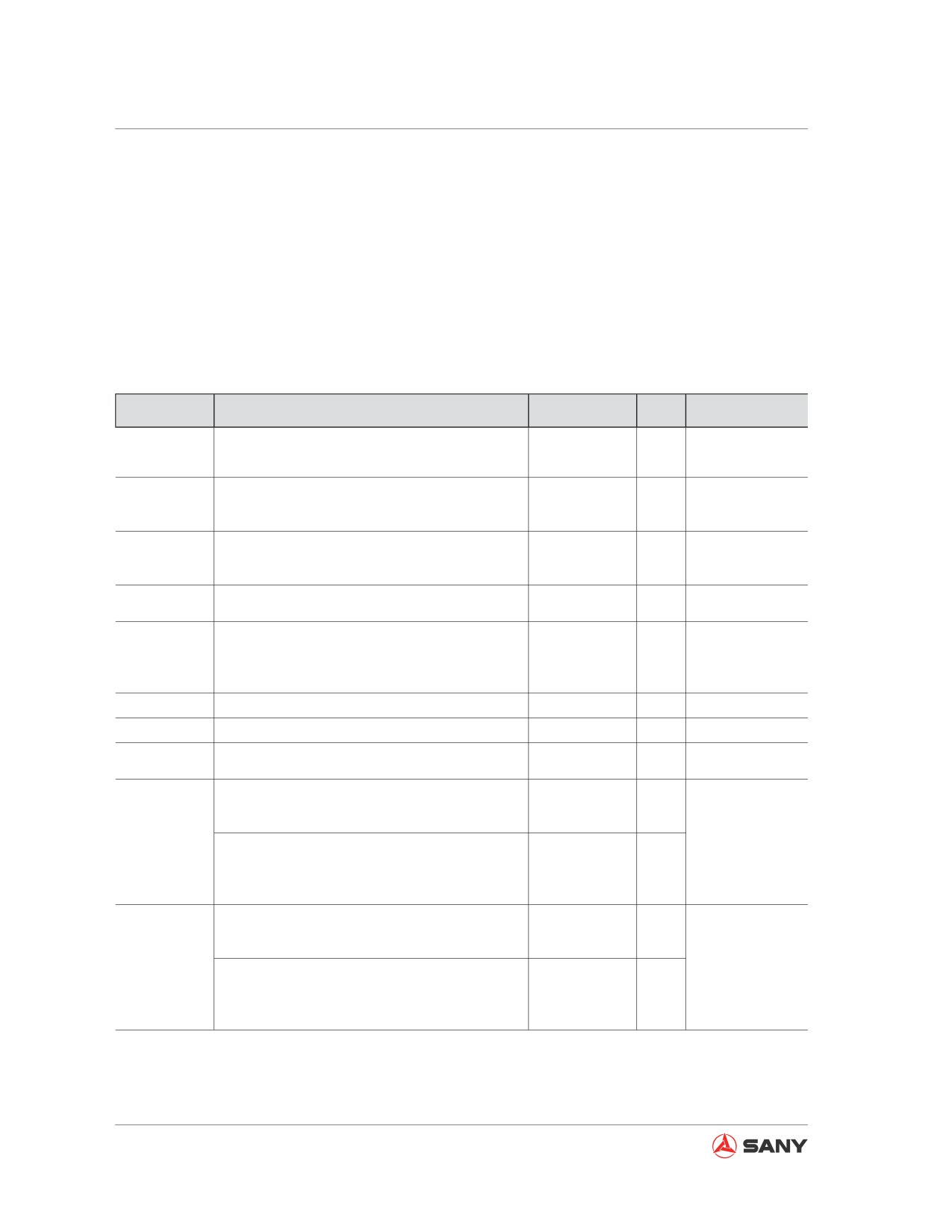
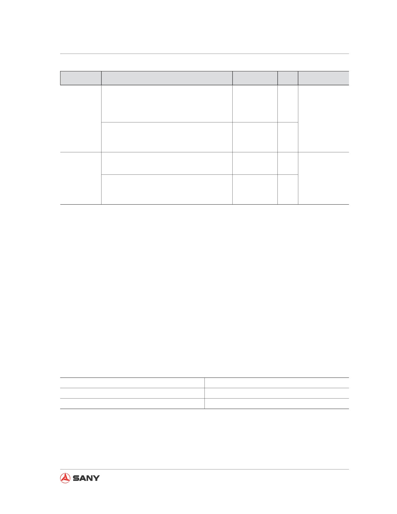
5.3 Replacement Parts
● Replacement parts, such as filter element and bucket tips, should be replaced according to
maintenance schedule or before the wearing limits are reached.
● Replacement parts shall be replaced properly in order to use your machine economically.
● Select Sany genuine quality parts for replacement.
● Check the part number in the Parts Manual when ordering a part.
Also replace the part in brackets.
Component
Part Number
Part
Qty
Interval
Fuel filter, pri-
60064761(SY115C9, SY135C8/C9, SY155H)
Filter element
1
Every 250 hours
mary
60033346(SY135C8(M))
B222100000453(SY115C9, SY135C8/C9,
Fuel filter, sec-
SY155H)
Filter
1
Every 250 hours
ondary
B222100000415(SY135C8(M))
B222100000488(SY115C9, SY135C8/C9,
Oil filter
SY155H)
Filter
1
Every 250 hours
B222100000386(SY135C8(M))
Filter element
1
Pilot filter
B229900000063
Every 500 hours
(O-ring seal)
(1)
Filter element,
Hydraulic oil
60101257
oil suction
1
Every 1000 hours
filter
60101256
Filter element,
(1)
oil return
Air filter, main
B222100000500
Filter element
1
─
Air filter, safety
B222100000501
Filter element
1
─
Breather valve
60174894
Filter element
1
Every 1500 hours
filter element
Lateral pin
60102737
Bucket tips
5
(60102738)
(Pin group)
(5)
Bucket
A229900007131
Left cutter
1
─
(SY115C)
A229900007130
Right cutter
1
(A210111000301)
(Bolt)
(8)
(A210307000006)
(Nut)
(8)
Lateral pin
10143956
Bucket tips
4
(10143975)
(Pin)
(4)
Bucket
A229900007131
Left cutter
1
─
(SY135C8)
A229900007130
Right cutter
1
(A210111000301)
(Bolt)
(8)
(A210307000006)
(Nut)
(8)
5-16
Maintenance
Component
Part Number
Part
Qty
Interval
Lateral pin
60100572
Bucket tips
4
(10143975)
(Pin)
(4)
A229900005244
Tip adaptor
4
Bucket
A229900005241
Tip pin
4
─
(SY135C9)
A229900007131
Left cutter
1
A229900007130
Right cutter
1
A210111000301
(Bolt)
(8)
60012073
(Nut)
(8)
Lateral pin
60100572
Bucket tips
4
(A229900005241)
(Pin)
(4)
Bucket
A229900007131
Left cutter
1
─
(SY155H)
A229900007130
Right cutter
1
(A210111000301)
(Bolt)
(8)
(A210307000006)
(Nut)
(8)
5.4 Recommended Fluids
● To keep your machine at the maximum state for a long period of time, it is necessary follow
the oil instructions described in this manual. Failure to do so can cause overwear and service
life reduction of the engine, power train, cooling system and other components.
● The additives available in market could benefit your machine, but they could impair your ma-
chine as well. We do not recommend any lubricant additives.
● The specific capacity refers to the overall oil volume in tanks and lines. Supplementary vol-
ume refers to the amount of oil used to make up the system in inspection and maintenance.
● The use of multigrade oils is strongly recommended when starting the engine at temperatures
below 0°C (32°F), even if the daytime temperatures rise above 0°C(32°F).
● Use the recommended oils according the ambient temperatures given in the following table.
● When the sulfur content of fuel is less than 0.5%, change the fuel according to the required
maintenance interval given in this manual. If the sulfur content is more than 0.5%, change the
fuel according to the following table:
Sulfur Content in Fuel
Oil-Change Interval - Engine Oil Pan
0.5
- 1.0%
1/2 of standard interval
More than 1.0%
1/4 of standard interval
Table 5-2
5-17
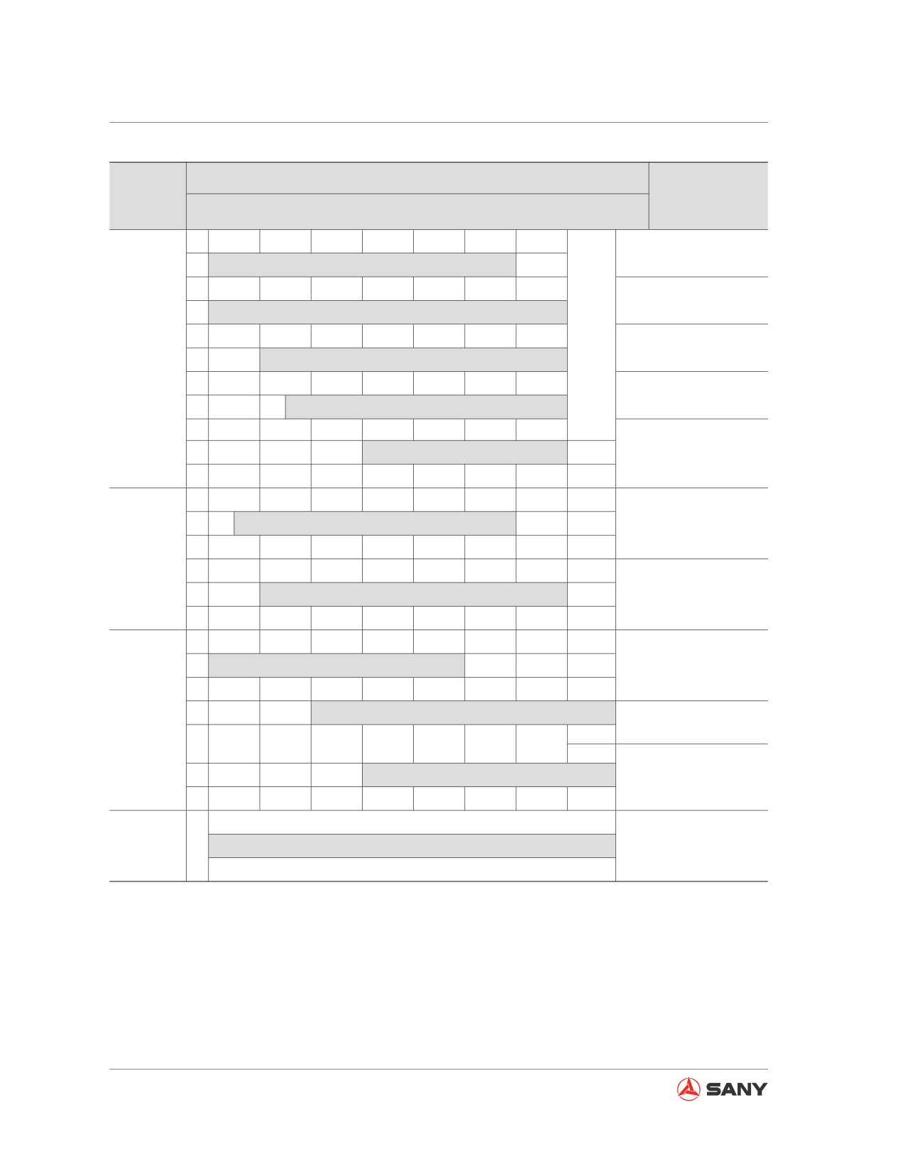
Maintenance
Ambient Temperature
Recommended
Fluid
-22
-4
14
32
50
68
86
104
122 °F
fluids
-30
-20
-10
0
10
20
30
40
50°C
5W-30
5W-40
10W-30
Oil
15W-40
(Note 1)
40
HDZ32
(ISO VG32)
Hydraulic
oil
HDZ46
(ISO VG46)
-30 diesel
Diesel fuel
-10 light diesel
0 light diesel
Coolant
TEEC-135
(Note 2)
antifreeze
Table 5-3
5-18
Maintenance
5.4.1 Fluid capacities
Engine Oil
Hydraulic
Cooling Sys-
Swing Drive
Final Drive
Fuel Tank
Pan*
System
tem
L
13.2(*)
3.0
2.5
150
16
240
US gal
3.5
0.79
0.66
39.62
4.23
63.4
Note:
* Capacity of engine oil pan on SY135C8M is 15 L (3.98 US gal).
Always use diesel oil as the fuel.
To ensure favorable consumption and exhaust of the fuel, the engine installed to your machine
uses high-pressure oil injection unit with mechanical control. The unit contains high-precision
components that require high-quality lubrication. Therefore, the use of low-viscosity fuel with low
lubricating capability will considerably reduce the service life of the unit.
Note 1: The HTHS (high-temperature high-shear viscosity at 150°C) required by ASTM D4741
must be equal to or more than 3.5 mPa-S. Sany strongly recommend the use of engine
oil 15W-40.
Note 2: Coolant
1) The coolant is also an important fluid against corrosion and freezing.
Antifreezing coolant is also necessary in regions where freezing prevention is unnecessary.
Sany machines are prefilled with TEEC-L35 antifreeze, which has excellent performance in
anticorrosion, antifreezing and cooling.
2) For more information on diluting TEEC-L35 antifreeze with water see “Cooling system -
clean” on page 5-37.
3) The proper concentration of coolant must be kept in order to ensure the coolant's performance
against corrosion.
Recommended brands and quality of recommended products besides Sany genuine oils
Consult your Sany distributor before using any oils other than those recommended by Sany.
5-19
Maintenance
5.4.2 Recommended oils:
1.
Engine oil
Select the oil of proper viscosity according
to the temperature range given in the oil
change schedule.
Engine oil grade: Above API CF-4
Recommended engine oil brand and type:
Caltex CH-4 15W-40
2.
Engine fuel
Light diesel oil (GB252.81)
● In most cases, the use of fuel ASTH2
and the diesel oil (minimum cetane
number is 40) can achieve the best
economic result and operating perfor-
mance. At where the elevation is high or
the ambient temperature is too low, it is
necessary to use the fuel whose cetane
number is more than 40 in order to pre-
vent flameout and too much smoke.
● When the fuel of low sulfur content is
used, its cloud point shall be at lease
10°C lower than the expected minimum
fuel temperature. Cloud point is the
temperature at which the waxy crystals
begin to form.
● The universal diesel fuel of commercial
brands shall contain sulfur that is less
than 0.5%.
● Clean fuel free from water and/or impu-
rities shall be ensured before refueling.
3.
Hydraulic oil
The hydraulic system uses Caltex HDZ46
hydraulic oil (code B420106000036).
When the ambient temperature is below
0°C, the following items have to be fol-
lowed to heat the hydraulic system in order
5-20
Maintenance
to ensure the safety of the hydraulic sys-
tem.
●
Run the engine at idle speed for 7-10
minutes before increasing its rpm to
1000 - 1200. Never operate your exca-
vator except running the engine unload-
ed for 30-40 minutes or longer in order
to heat the hydraulic oil to a tempera-
ture above 20°C.
●
Now your machine can be used for
normal construction operation after the
hydraulic oil temperature rises above
20°C. However, the heating time shall
be adjusted according to ambient tem-
perature. In normal construction work,
the joystick controls and pedals shall be
maneuvered slowly while paying close
attention to the system's running condi-
tion. Operating your machine with the
hydraulic oil temperature being below
20°C could damage the hydraulic ele-
ments.
●
Anti-friction hydraulic oil L-HM46 is
widely used in temperate zones.
●
Low-temperature, anti-friction hydraulic
oil L-HV32, whose pour point is -42°C,
is used in extremely cold regions (below
-30°C) such as Russia and Northeast
China.
●
Anti-friction hydraulic oil L-HM68 is gen-
erally used in torrid regions such as the
Middle East and India.
●
Select proper hydraulic oil according to
the region where your machine is to be
operated. The machine has been filled
with hydraulic oil of suitable brand and
type before it is delivered. User is re-
sponsible to change the oil after the ma-
chine is delivered. You may consult our
after-sale service personnel to obtain
correct brand and type of the hydraulic
oil.
5-21
Maintenance
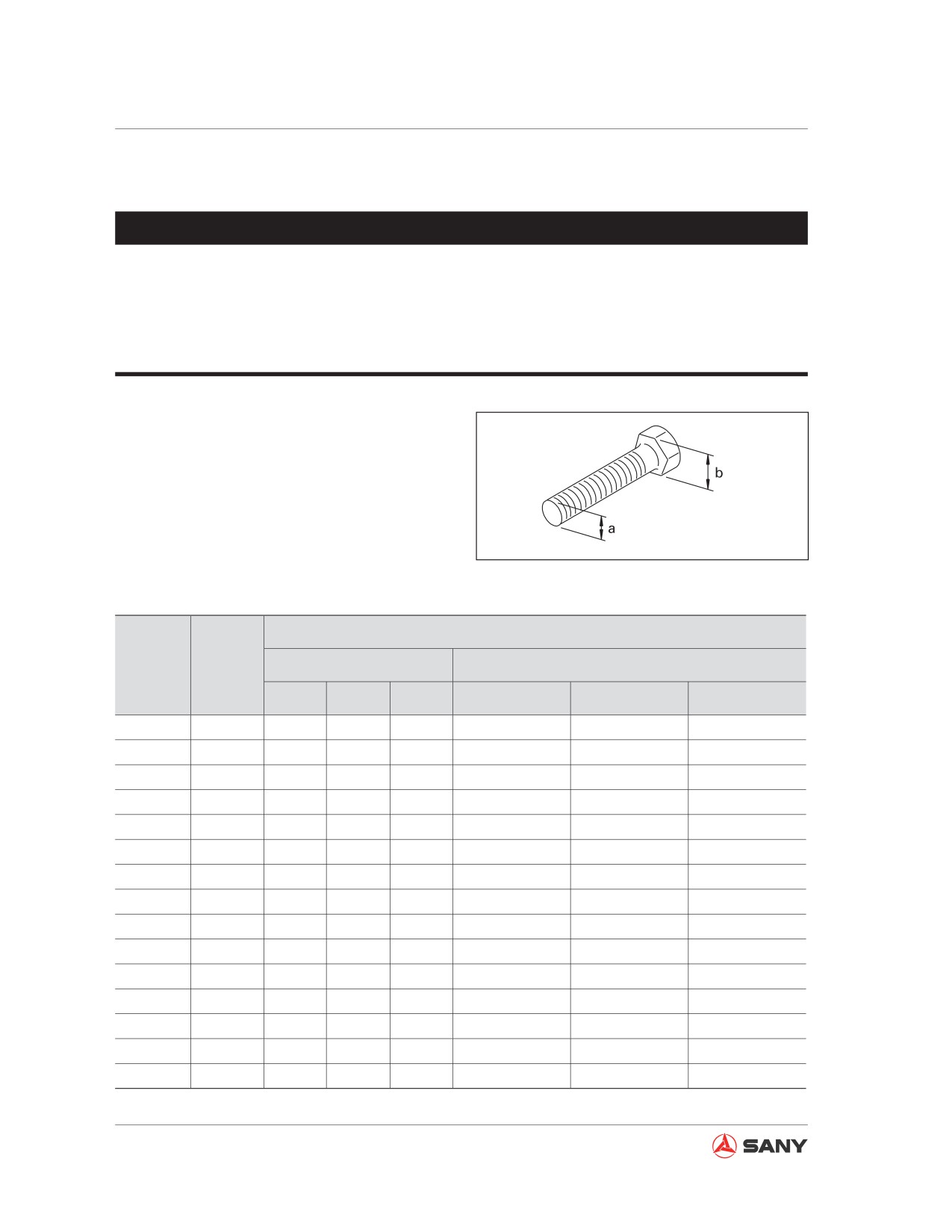
5.5 Tightening Torque Specification
NOTICE
● The nuts, bolts or other parts having not been tightened to specific torque values can
lead to loose or damaged parts, hence resulting in machine failure and operating trou-
bles.
● Special attention shall be paid when tightening any parts.
Unless specified otherwise, the metric nuts
and bolts shall be tightened to the values giv-
en in the following table.
The tightening of torque is determined by the
width of screw cap or nut.
CZ335-1104001
In replacement of the bolts or nuts, use Sany
Fig. 5-1
genuine parts of equivalent size.
Tightening Torques
Thread
Square
Diameter
Size
Target Values
Torque Limits
a
b
(mm)
(mm)
N·m
kgf·m
lbft
N·m
kgf·m
lbft
6
10
13.2
1.35
9.8
11.8
- 14.7
1.2
- 1.5
8.7
- 10.8
8
13
31
3.2
23.1
27 - 34
2.8
- 3.5
20.3
- 25.3
10
17
66
6.7
48.5
59 - 74
6.0
- 7.5
43.4
- 54.2
12
19
113
11.5
83.2
98 - 123
10.0
- 12.5
72.3
- 90.4
14
22
177
18
130.2
157 - 196
16.0
- 20.0
115.7
- 144.7
16
24
279
28.5
206.1
245 - 309
25.0
- 31.5
180.8
- 227.8
18
27
382
39
282.1
343 - 425
35.0
- 43.5
253.2
- 314.6
20
30
549
56
405
490 - 608
50.0
- 62.0
361.7
- 448.4
22
32
745
76
549.7
662 - 829
67.5
- 84.5
488.2
- 611.2
24
36
927
94.5
683.5
824 - 1030
84.0
- 105.0
607.6
- 759.5
27
41
1320
135
976.5
1180 - 1470
120.0
- 150.0
868.0
- 1085.0
30
46
1720
175
1265.8
1520 - 1910
155.0
- 195.0
1121.1
- 1410.4
33
50
2210
225
1627.4
1960 - 2450
200.0
- 250.0
1446.6
- 1808.3
36
55
2750
280
2025.2
2450 - 3040
250.0
- 310.0
1808.3
- 2242.2
39
60
3280
335
2423.1
2890 - 3630
295.0
- 370.0
2133.7
- 2676.2
Table 5-4
5-22
Maintenance
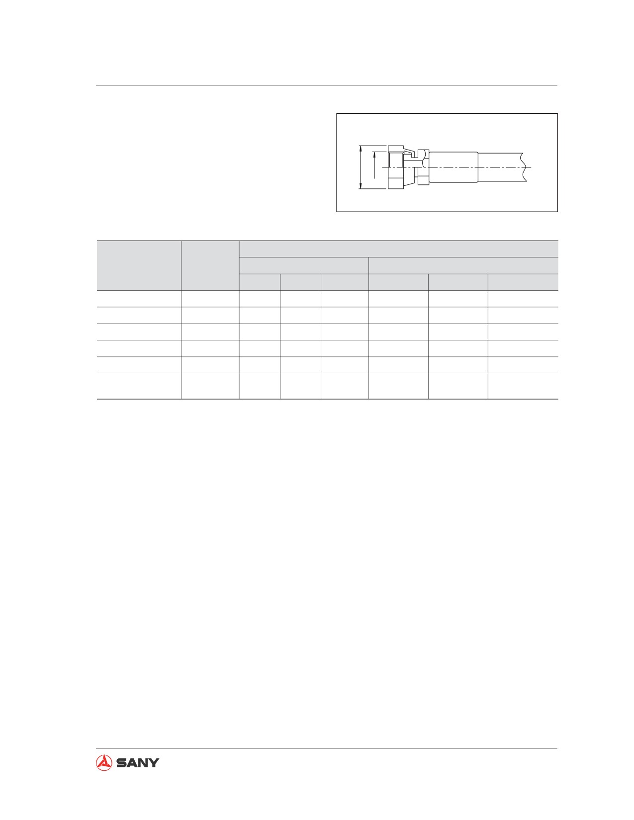
Hydraulic hoses are tightened according to the
torques given below.
b
a
Fig. 5-2
Nominal Thread
Tightening Torques
Square Size
Number
Target Values
Permissible Range
(b)(mm)
(a)
N·m
kgf·m
lbft
N·m
kgf·m
lbft
9/16-18UNF
19
44
4.5
32.5
35-63
3.5-6.5
25.3-47
11/16-16UN
22
74
7.5
54.2
54-93
5.5-9.5
39.8-68.7
13/16-16UN
27
103
10.5
75.9
84-132
8.5-13.5
61.5-97.6
1-14UNS
32
157
16.0
115.7
128-186
13.0-19.0
94-137.4
13/16-12UN
36
216
22.0
159.1
177-245
18.0-25.0
130.2
-180.8
☆ 1 -7/16 - 12UN
41
215
22.0
159.1
176-234
18.0-24.0
130.2-180.8
- 2B
Table 5-5
Note: The item marked with ☆ is used for tightening the hose on top of the swivel joint.
5-23
Maintenance
5.6 Safety-Related Parts
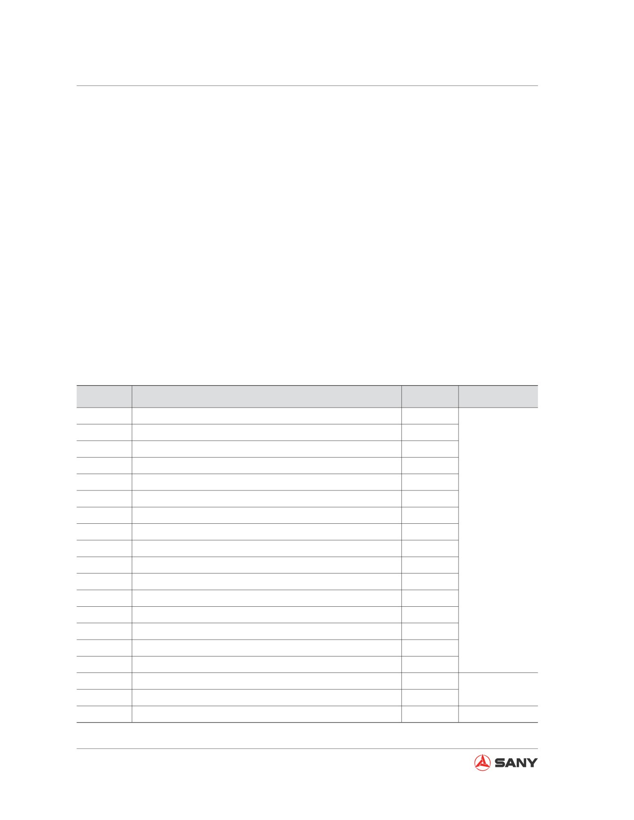
To ensure your safety during operating or driving the machine, user shall carry out regular main-
tenance on the machine. In addition, user shall also replace the parts listed in the table in order to
further improve the safety condition. These parts are closely related to safety and fire prevention.
Since the safety-related parts may become easily worn or deteriorated due to material changing
along with the time, it is hard to judge their conditions through regular maintenance. These parts
shall be replaced as scheduled regardless of their conditions, which can effectively guarantee the
functions of these parts.
If any safety-related part becomes abnormal before its scheduled replacement, it must be re-
paired or replaced immediately.
If any hose deteriorates, such as deforming or cracking, the hose clamps shall also be replaced
while replacing the hose.
O-ring, gasket and other similar parts shall also be replaced while replacing a hose.
Consult your Sany distributor to replace the following safety-related parts on a regular basis.
No.
Safety-related parts subject to regular replacement
Quantity
Frequency
1
Fuel hose (fuel tank - water separator)
1
2
Fuel hose (water separator - primary filter)
1
3
Fuel return hose (engine - fuel tank)
1
4
Fuel hose (primary filter - engine)
1
5
Pump outlet hose (pump - control valve)
2
6
Work equipment hose (boom cylinder oil inlet)
4
7
Work equipment hose (Bucket cylinder line - boom root)
2
Every 2 years
8
Work equipment hose (bucket cylinder oil inlet)
2
or 4000 hours,
9
Work equipment hose (arm cylinder line - boom root)
2
whichever occurs
first.
10
Work equipment hose (arm cylinder oil inlet)
2
11
Swing drive hose (swing motor oil inlet)
2
12
Main oil suction hose
1
13
Travel control hose (control valve - swivel joint)
4
14
Travel control hose (swivel joint - travel motor)
4
15
Pump pressure hose
1
16
Accumulator (control oil)
1
17
High-pressure tube clamps
1
Every 8000 hours
18
Cover - fuel squirt prevention
1
19
Seat belt
1
Every 3 years
Table 5-6
5-24
Maintenance
5.7 Maintenance Schedule
If your machine is equipped with hydraulic breaker, the maintenance schedule for some parts
may vary. For more information and proper maintenance see "Hydraulic Breaker Maintenance
Schedule."
5.7.1 List of maintenance schedule
Maintenance after initial 50 service hours
5-28
Engine oil and filter - change/replace
5-28
Fuel filter - replace
5-28
When Required
5-29
Air cleaner - clean/replace
5-29
Cooling system - clean
5-37
Track shoe bolts - inspect/tighten
5-41
Track tension - inspect/adjust
5-42
Bucket tips (lateral pin) - replace
5-45
Bucket Replacement
5-47
Bucket clearance - adjust
5-49
Window washer fluid - check/refill
5-51
Air conditioner - inspect/service
5-52
Gas spring - inspect
5-54
Air in hydraulic system - purge
5-55
Hydraulic circuit internal pressure - release
5-58
Checks before starting
5-59
Every 100 service hours
5-60
Lubrication
5-60
Every 250 service hours
5-63
Compressor belt tension - inspect/adjust
5-63
Oil in engine oil pan and oil filter - change/replace
5-65
Primary fuel filter - replace
5-67
Secondary fuel filter - replace
5-71
Every 500 service hours
5-74
5-25
Maintenance
Swing bearing - lubricate
5-74
Swing pinion gear grease - check/refill
5-75
Coolant tank and radiator fins - inspect/clean
5-76
Air conditioner filters - clean
5-77
Swing drive oil - check/refill
5-80
Final drive oil - check/fill
5-81
Every 1000 service hours
5-82
Hydraulic oil filter - replace
5-82
Swing drive oil - change
5-84
Engine exhaust pipe clamps - check
5-85
Fan belt tension - check/replace
5-85
Nitrogen pressure in accumulator (breaker) - check
5-85
Every 2000 service hours
5-86
Final drive oil - change
5-86
Hydraulic tank filter screen - clean
5-88
Nitrogen pressure in accumulator (control oil circuit) - check
5-89
Hydraulic circuit internal pressure - release
5-92
Oil in hydraulic tank - change
5-93
Alternator - inspect
5-95
Engine valve clearance - check/adjust
5-95
Every 4000 service hours
5-95
Coolant pump - inspect
5-95
Start motor - check
5-95
Accumulator (control oil circuit) - replace
5-96
High-pressure tube clamps and rubber - check
5-97
Compressor working condition - inspect
5-97
Every 8000 service hours
5-98
High-pressure tube clamps - replace
5-98
Every 10000 service hours
5-98
5-26
Maintenance
5.7.2 Hydraulic Breaker Service Interval
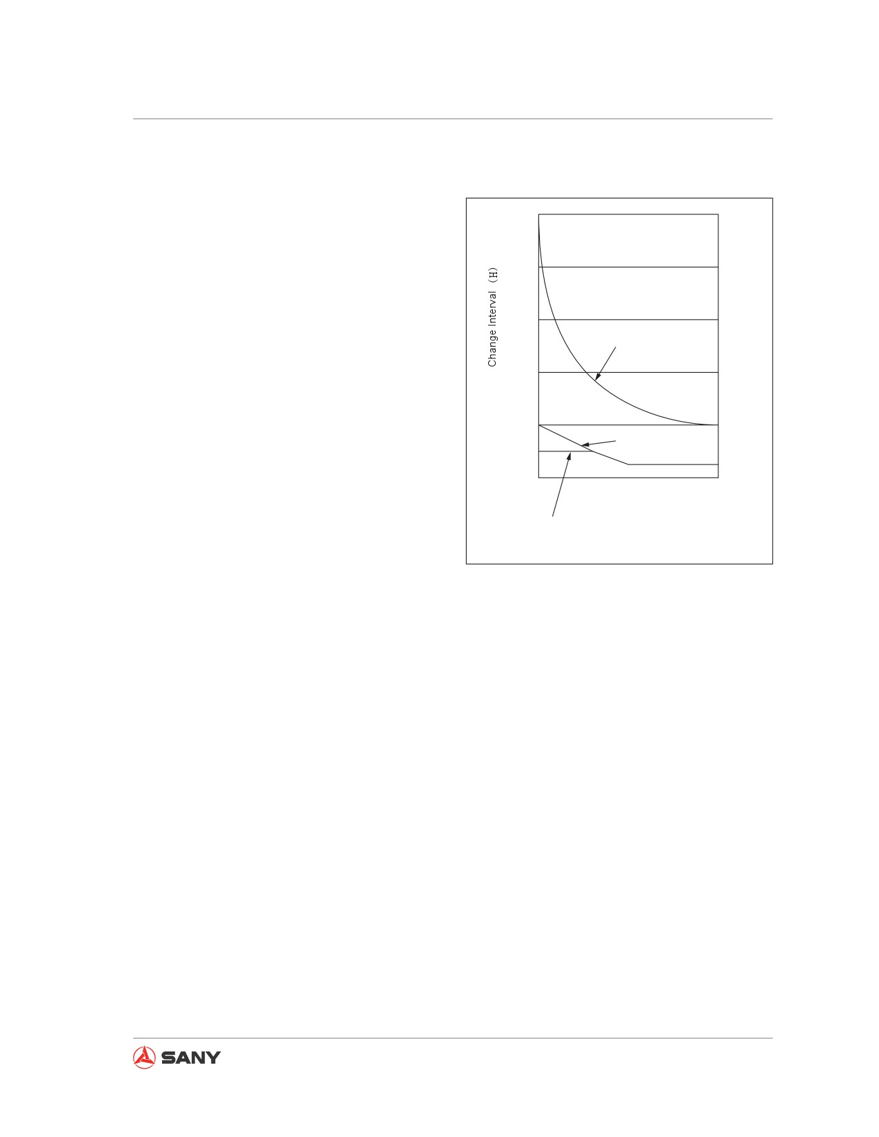
For machines equipped with a hydraulic
5000
breaker, the hydraulic oil deteriorates faster
(H)
than that of machines operating with a bucket.
In this case, the following steps shall be fol-
4000
lowed in order to adjust the service intervals.
● Change hydraulic filter element
3000
Hydraulic oil change interval
For a new machine, the filter element is to
be replaced after the first 100-150 service
2000
hours. Subsequent replacement shall be
carried out according to the right chart.
1000
● Change the oil of hydraulic tank
Hyd filter element
500
Pilot filter element
Change the oil according to the right chart.
When unused
0
20
40
60
80
100
(%)
● Replace the additional filter element (if
When used
equipped) of the breaker
Additional filter element
Replace the pilot filter element (if
CZ335-1104003
equipped).
Fig. 5-3
The filter element is to be replaced accord-
ing the right chart when the breaker has
served for 250 hours (breaker operating
proportion more 50%).
Remark:
100% breaker operation means that the break-
er is used all the time, while 0% means that
the breaker never used.
5-27
Maintenance
5.8 Maintenance Procedures
5.8.1 Maintenance after initial 50 ser-
vice hours
The following maintenance is to be carried out
after initial 50 service hours.
Consult your Sany distributor for special tools
used for checks and maintenance.
5.8.1.1 Engine oil and filter - change/
replace
For the procedures of changing engine oil and
replacing oil filter see “Oil in engine oil pan
and oil filter - change/replace”on page 5-65.
5.8.1.2 Fuel filter - replace
For the procedures of replacing fuel filters see
“Primary fuel filter - replace”on page 5-67
and “Secondary fuel filter - replace” on
page 5-71.
5-28