SANY Crawler Hydraulic Excavator SY115C9, SY135C8, SY135C9, SY155H. Safety, Operation and Manitenance Manual - page 6
Operation
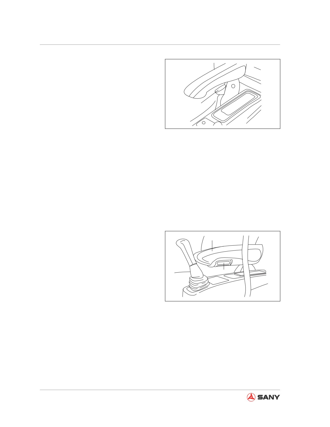
(B) Backrest adjustment
Lift lever (2), move the backrest to an optimum
position at where operation can be easily con-
ducted, and release the lever.
Make sure the backrest does not interferes
2
with the cover plate of the air conditioner at
rear when adjusting the inclination of backrest.
CZ335-1103140
Be careful with the control levers, which shall
not be touched by armrest.
Fig. 4-23
(C) Height adjustment
The seat can be raised by 30 mm when you
hear a "click" sound, and another 30 mm at
the second "click". The seat can be lowered to
the minimum height if you continue to raise it.
Adjustable height: 60mm (30mm for each ad-
justment)
(D) Armrest angle adjustment
Turning the plate (4) beneath armrest (3) can
adjust the angle of armrest to desired position.
3
The armrest can be placed vertically so that
the operator could leave the seat easily.
4
Adjustable angle: 40°
CZ335-1103141
Fig. 4-24
4-16
Operation
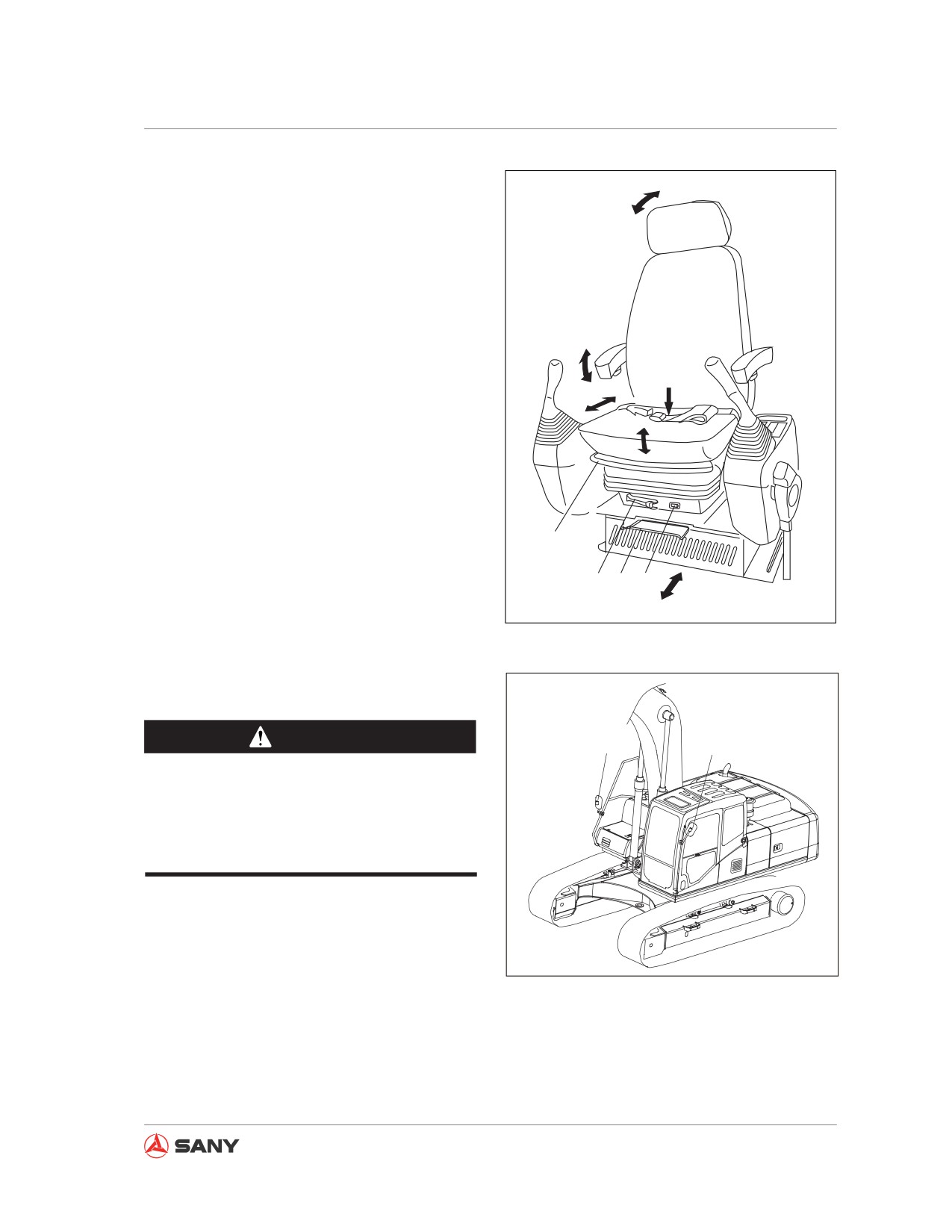
(E) Adjust the seat forward and backward
B
as a whole
Pull the lever (5), slide the seat to desired po-
sition, and release the lever. In this case, the
operator seat moves along with both armrest
boxes and pilot hydraulic lockout control.
(F) Suspension adjustment (if equipped)
D
Turning the lever (6) counterclockwise will
F
A
bring you a hard suspension which is suitable
for heavy operator; turning the lever (6) clock-
C
wise will bring you a soft suspension which is
suitable for light operator.
Remark:
1
To achieve the best adjustment, adjust the
reading (kg) on dial (7) to weight of operator.
6
5
7
E
CZ335-1103139
Fig. 4-26
4.1.3.2 Rear view mirrors
WARNING
B
A
The rear mirrors must be adjusted before
operation. Without proper adjustment,
a good visibility cannot be ensured and
which may lead injury.
CZ335-1103238
Fig. 4-25
4-17
Operation
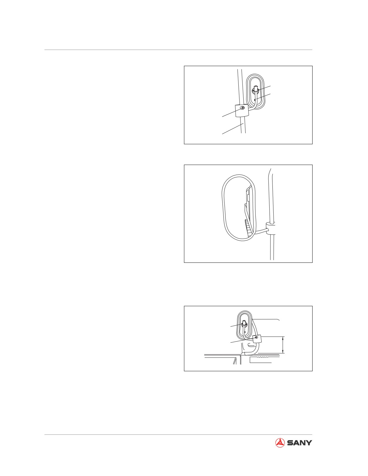
Rear mirror (A)
Adjust installation of rear mirror (A) so that
2
people to rear left of machine can be seen
1
clearly.
Install rear mirror (A) to the position as shown
3
in the right illustration.
4
CZ335-1103143
Turn the rod (1) around rod (4) to a suitable
position and fix rod (1).
Fig. 4-27
When adjusting mirror angle, if the mirror can-
not move smoothly, you may loosen bolt (2)
and bolt (3) to release the mirror.
Torque of bolt (2):
4.0~5.4 N·m (0.41~0.55 kgf·m)
Adjustment of rear mirror is accomplished
when side of machine can be seen in the mir-
ror, as shown in the right illustration.
CZ335-1103144
Fig. 4-28
Rear mirror (B)
Adjust installation of rear mirror (B) so that
people to rear right of machine can be seen
clearly.
5
Install rear mirror (B) to the position as shown
6
in the right illustration.
M
M: 120 mm
CZ335-1103145
Fig. 4-29
4-18
Operation
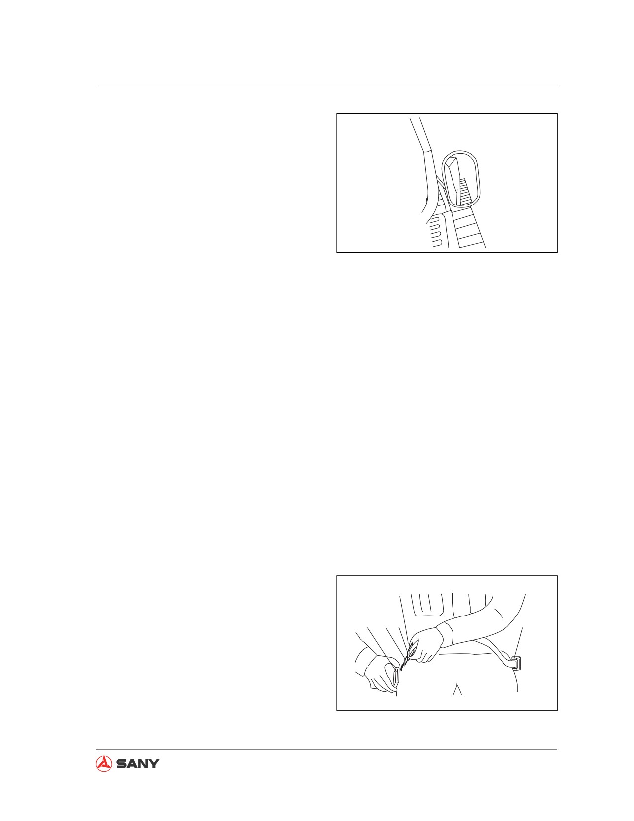
When adjusting mirror angle, if the mirror can-
not move smoothly, you may loosen bolt (5)
and bolt (6) to release the mirror.
Torque of bolt (5): 4.0~5.4 N·m
(0.41~0.55 kgf·m)
Adjustment of rear mirror is accomplished
when side of machine can be seen in the mir-
CZ335-1103146
ror, as shown in the right illustration.
Fig.
4-30
4.1.3.3 Seat belt
● Check the condition of the seat belt and
the buckle before you fasten it. Replace
the belt if excessive wear or damage is
observed.
● Replace the seat belt every 3 years re-
gardless of its condition. See the produc-
tion date on the back of the belt.
● Be sure to fasten your seat belt during ma-
chine operation.
● Never twist the seat belt.
Buckle up and release
The seal belt has a coiler, and belt length
needs no adjustment.
1. Buckle up
Hold clip (2) and pull the belt out of coiler
(1). Check that there is no twist on the belt
and insert catch (3) into buckle (4).
Check if the belt has been fastened by
pulling it slightly.
4đ5
3
2
1
2. Release
Press button (5) on buckle (4) to release
catch (3). The belt will retract into the coil-
er automatically.
CZ335-1103147
Hold clip (2) so that the belt retract slowly
Fig. 4-31
into the coiler.
4-19
Operation
4.1.4 Before Starting the Engine
WARNING
● Before starting the engine, check the
hydraulic lockout control whether it is
secured in "locked" position.
● If the hydraulic lockout control is not
secured in position, accidental touch-
ing of control lever or pedal when start-
ing the engine may lead to unexpected
movement of machine, which could
cause serious accident.
● When rising from operator seat, make
sure the hydraulic lockout control is in
LOCK position, regardless of that the
engine is running or not.
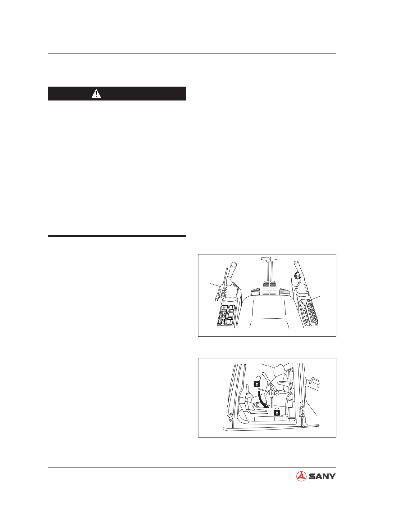
1. Check if the hydraulic lockout control (1) is
in the LOCK position (L).
2. Check if all control levers and pedals are in
1
a NEUTRAL position. They should remain
2
in NEUTRAL position if left touched.
Fig. 4-32
F
L
CZ335-1103149
Fig. 4-33
4-20
Operation
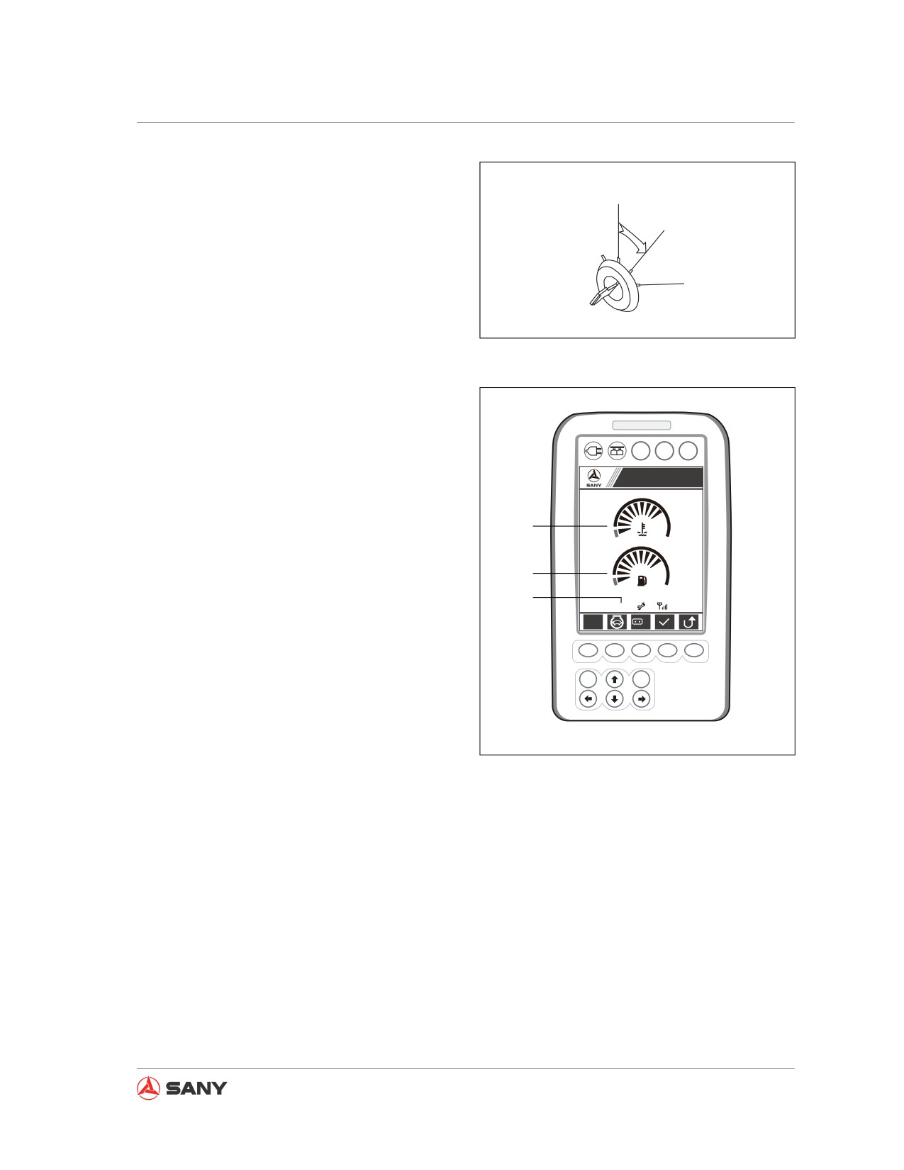
3. Insert your key into start switch (2), turn
the key to ON position (B), and then check
A
the following:
B
C
CZ335-1103150
Fig. 4-34
Two seconds after the key is turned to ON po-
sition, default screen will be displayed under
normal condition, as shown in the right illustra-
tion.
A B C
Sany Hydraulic Excavtor
● Engine coolant temperature gauge (3)
S
1
● Fuel level gauge (4)
3
● Failure code (5)
4
5
09/03/05
0000h 00m
12
12:25:31
S
Lo
F1
F2
F3
F4
F5
ESC
Enter
CZ135-1103002
Fig. 4-35
4-21
Operation
4.2 Engine Starting
WARNING
● Always start the engine from the opera-
tor seat.
● Never start the engine in a way that
may cause short circuit, which can lead
to serious injury or fire.
● Sound the horn and start the engine
after you have confirmed that the sur-
rounding area is clear of personnel or
barriers.
● Never use start-assisting solution as
which may cause explosion.
● Exhaust gas is poisonous. Pay special
attention to keeping a good ventila-
tion when starting the engine in an en-
closed space.
Note:
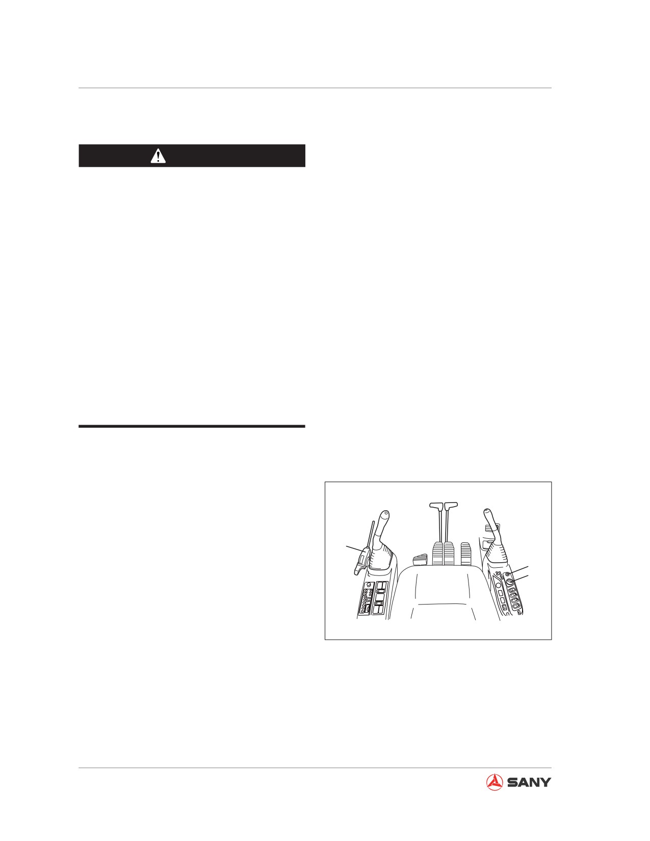
● Before starting the engine, check that the
fuel control dial (2) is in MIN position for
low idling speed. If the knob is in MAX po-
sition, starting the engine can lead to sud-
den acceleration and damage to its parts.
1
● Never keep the ignition key in START
3
position for more than 20 seconds.
2
If the engine fails to start, wait at least two
minutes before restarting it.
● After the engine is started, operation is not
CZ335S-1103062
allowed until oil pressure stays in the nor-
mal range. Never manipulate any control
Fig. 4-36
lever or pedal in case of abnormal oil pres-
sure.
4-22
Operation
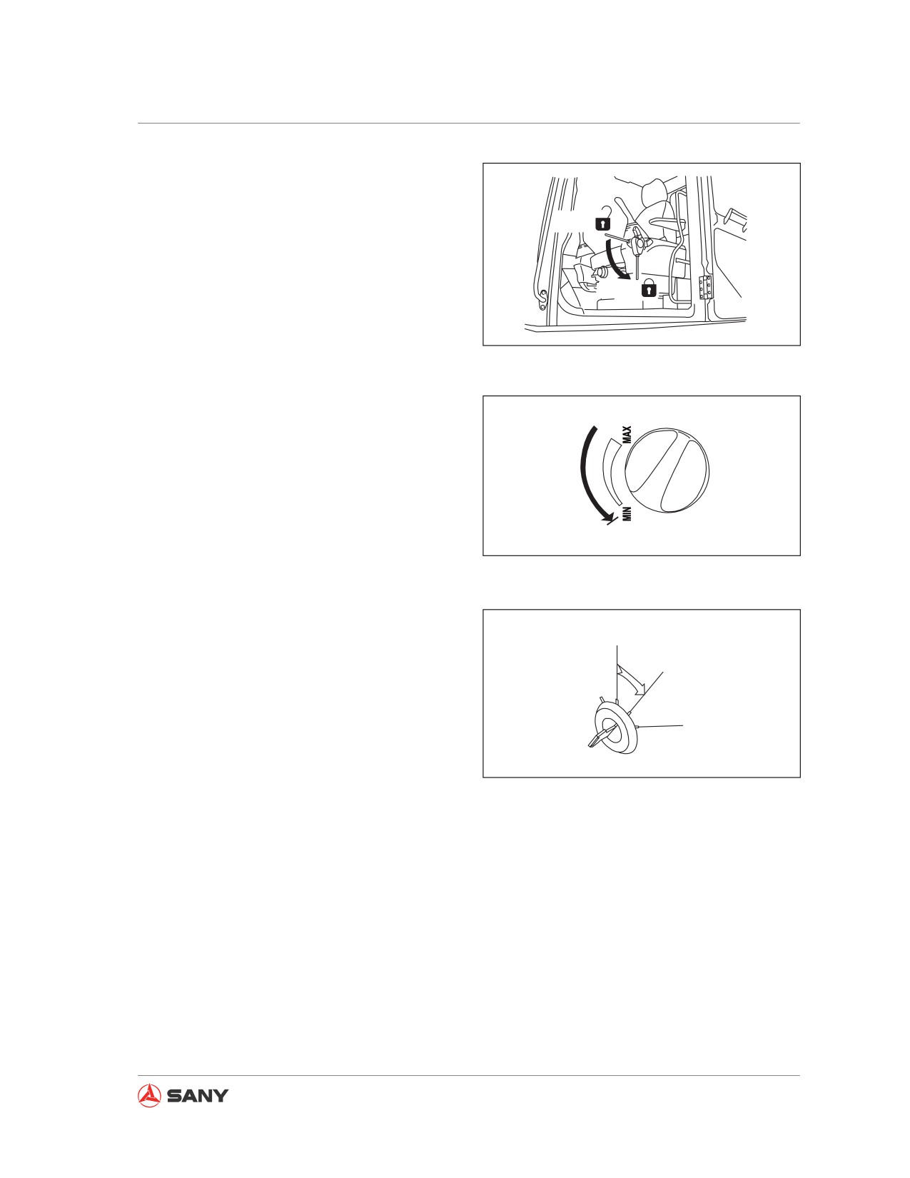
1. Check if the hydraulic lockout control (1)
is in the LOCK position (L). If it remains in
FREE position (F), the engine cannot be
F
started.
L
CZ335-1103149
Fig. 4-37
2. Turn the fuel control dial (2) to MIN posi-
tion.
CZ335-1103153
Fig. 4-38
3. Turn the ignition key to ON position (B).
A
B
C
CZ335-1103154
Fig. 4-39
4-23
Operation
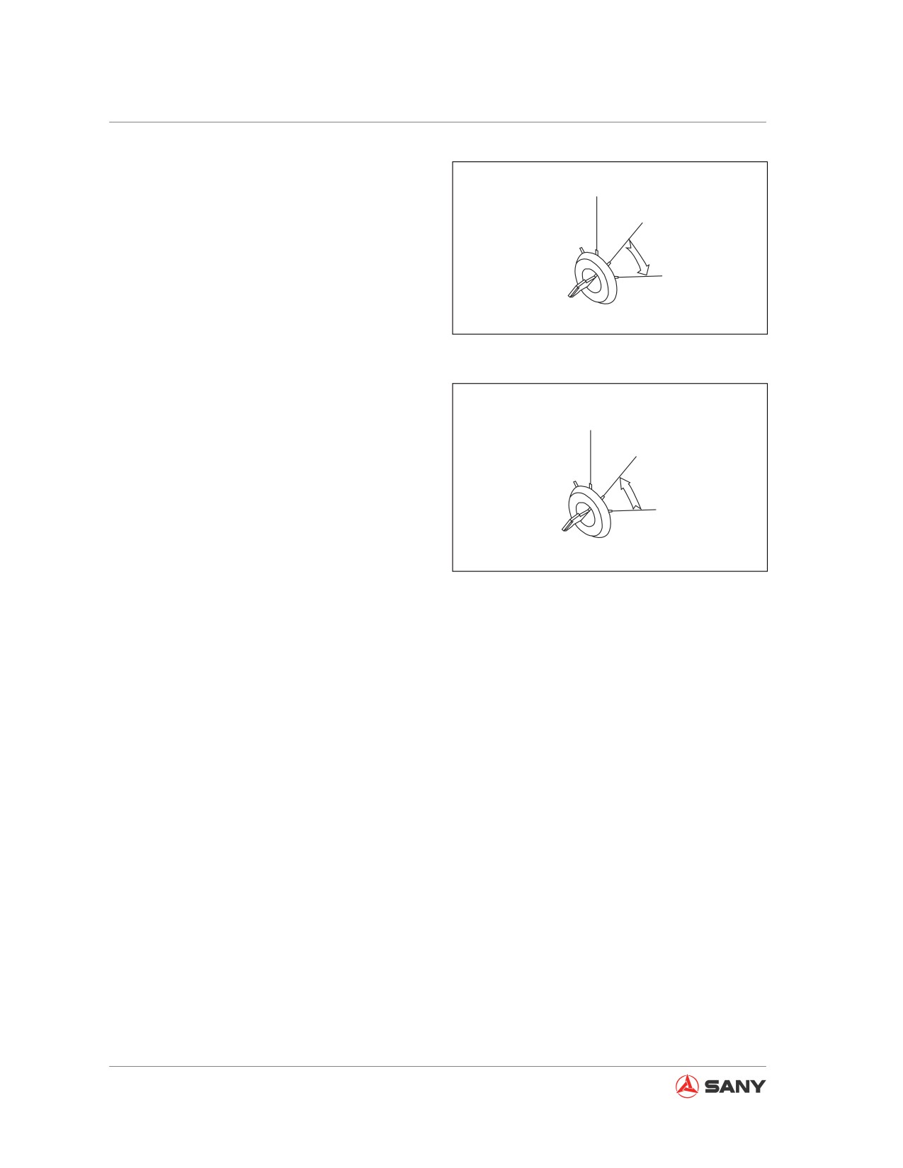
4. Turn the ignition key to START position (C).
A
B
C
CZ335-1103155
Fig. 4-40
5. Release the key (3) after starting the
engine. The key will be back to the ON
A
position (B) by itself.
B
Remark:
When ambient temperature is low, the engine
C
may fail to start after the start switch is kept at
START position for more than 10 seconds. In
CZ335-1103156
this case, wait at least for 1 minute before re-
starting the engine.
Fig. 4-41
6. Wait until engine oil pressure alarm is
reset even if the engine is started. Never
maneuver any control lever or pedal when
engine oil is abnormal.
Note:
If oil pressure remains abnormal after 4-5
seconds, immediately shut down the engine,
check oil level and check for oil leak. Take
necessary actions in case of abnormality.
4-24
Operation
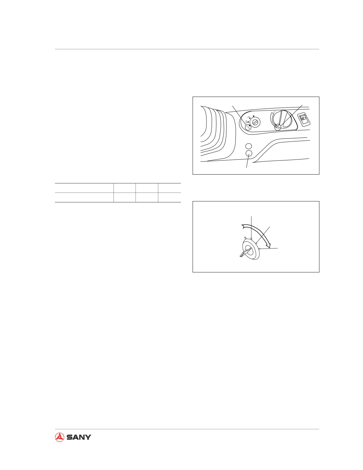
4.2.1 Engine Preheating
When ambient temperature is below 10ºC, it is
necessary to preheat the engine before start-
ing.
a
b
START
1. For model SY135C8M
Turn the fuel control dial to MIN position (b),
and turn the ignition key to HEAT position
(a). At the same time, switch on the pre-
heat switch. When preheating indicator (c)
lights, engine preheating begins. See the
following table for preheating period.
c
CZ335-1103247
Temperature (ºC)
0~10
-10~0
<-10
Preheating period
10s
20s
30s
A
2. For models SY115C9, SY135C8, SY
135C9 and SY155H
B
Turn fuel control dial to the MIN position (b).
Turn ignition key to the HEAT position (a).
C
The preheat indicator (c) will be on and the
engine begins preheating. The preheat in-
CZ335-1103157
dicator (c) will be off after preheating. The
engine is now ready to start up.
● After preheating, turn the ignition key to
the START position (C) to start the en-
gine.
● If the engine fails to start, wait at least
one(1) minute before re-preheating and
restarting the engine.
4-25
Operation
4.2.2 Warm-up operation
WARNING
● In case of emergency, abnormal running of engine, or other faults, turn the start switch
to OFF position and shut off the engine.
● Never operate any control lever or pedal suddenly when temperature of hydraulic oil is
low. Make sure to preheat the machine till temperature of hydraulic oil rises to a suit-
able point.
● Failure code 37 will be displayed when hydraulic oil becomes abnormal in tempera-
ture.
● If the machine has not been preheated completely, it may fail to respond or move sud-
denly and quickly during operation, and cause serious accidents. Complete warming-
up is especially necessary in cold region.
● Never accelerate your machine suddenly before finishing preheat operation. Never
continuously run the engine at low or high speed for more than 20 minutes, which
may cause leaks in oil supply pipe of turbo charger. If the engine has to be run at idle
speed, it is necessary to add load to it or run it at a moderate speed.
Never enter into operation immediately after starting the engine. Proceed and check the following
items:
1. Adjust fuel control dial to make the engine run unloaded at low speed (about 1,100 rpm) for
about five minutes.
2. Adjust fuel control dial to make the engine run at moderate speed (about 1,400 rpm), and then
slowly operate the bucket for five minutes.
3. Adjust fuel control dial to make the engine run at high speed, and operate the boom, arm and
bucket for 5-10 minutes.
4. Cycle each action of excavator for several times before ending the preheat operation.
5. Check all gauges for normal display after preheating the machine.
Continue to preheat the machine if coolant temperature (see display) and hydraulic oil tem-
perature (50~80℃ ) fail to reach normal values.
6. Check exhaust color, noise or vibration for abnormality. Repair it if any.
4.2.3 Selecting a working mode
Press the working mode selection key F1 on machine monitor to choose a mode you want.
For more information see “Working mode” on page 4-37.
4-26
Operation
4.3 Engine Shutdown
Remark:
● Shutting off the engine suddenly may con-
siderably reduce service life of its compo-
nents.
● Never shut off the engine suddenly except
1
for emergency.
● Never shut off the engine suddenly if the
engine is too hot. Run the engine at low
CZ215-1103061
idle in order to let it cool down gradually.
Stop the engine.
Fig. 4-42
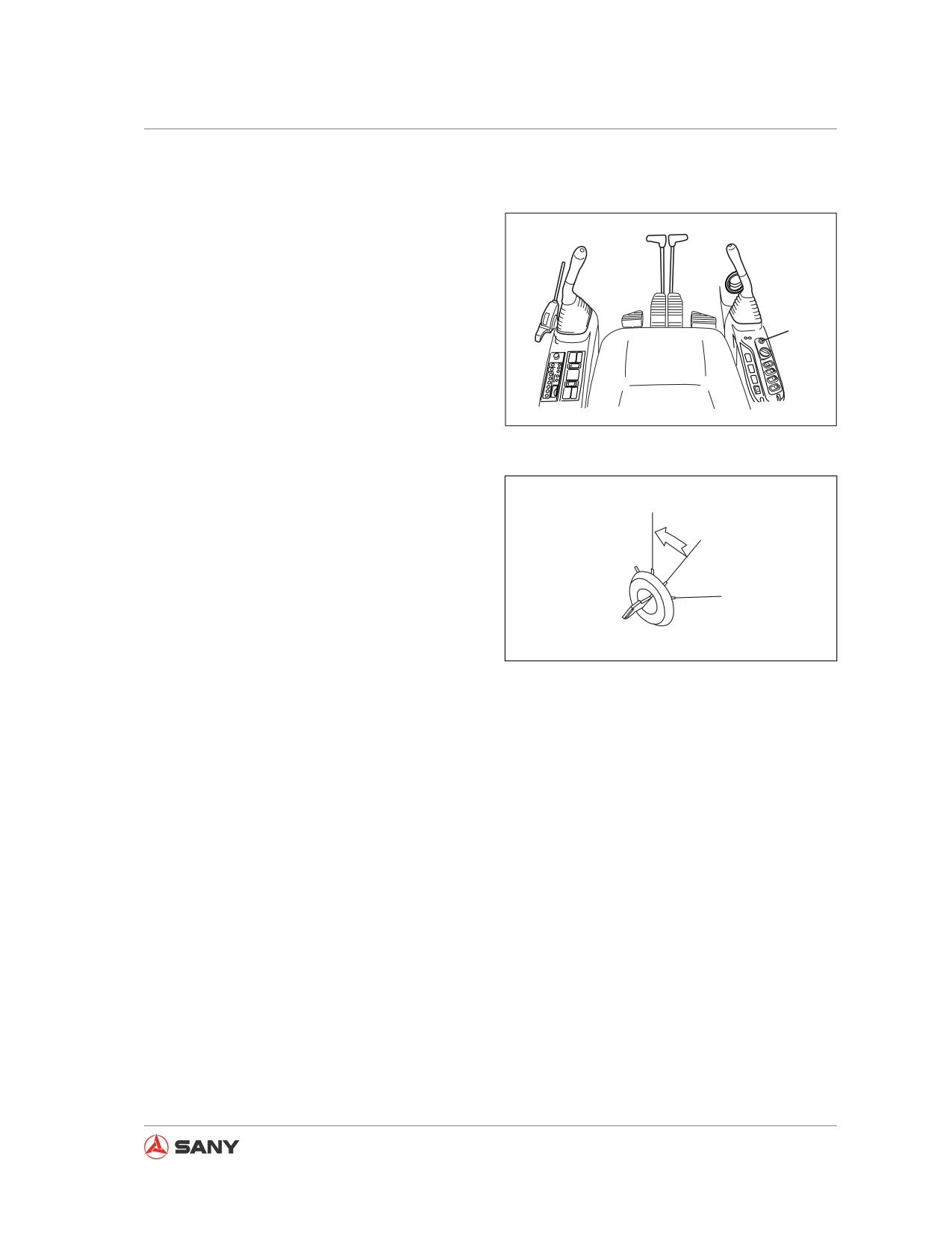
1. Run the engine at idle speed for about five
minutes to cool it down gradually.
A
2. Turn the start switch key (1) to OFF posi-
B
tion (A) to shut off the engine.
3. Remove the key (1) from the start switch.
C
CZ335-1103158
Fig. 4-43
4-27
Operation
4.4 Machine Operation
WARNING
● Check the surrounding of machine for safety and sound the horn before moving the
machine.
● Nobody is allowed to enter the area around the machine.
● Remove any barriers from the travel route.
● There is a blind area behind the machine. Therefore, pay special attention to reverse
travel.
● Check alarm devices for normal functioning before moving the machine.
Check the correct travel direction before operating travel control lever or pedal. If the track frame
faces the rear (behind the sprockets), the machine will move in a direction opposite to the operat-
ing direction of travel control lever or pedal (Both the forward and backward travels are reversed,
and the leftward and rightward travels as well).
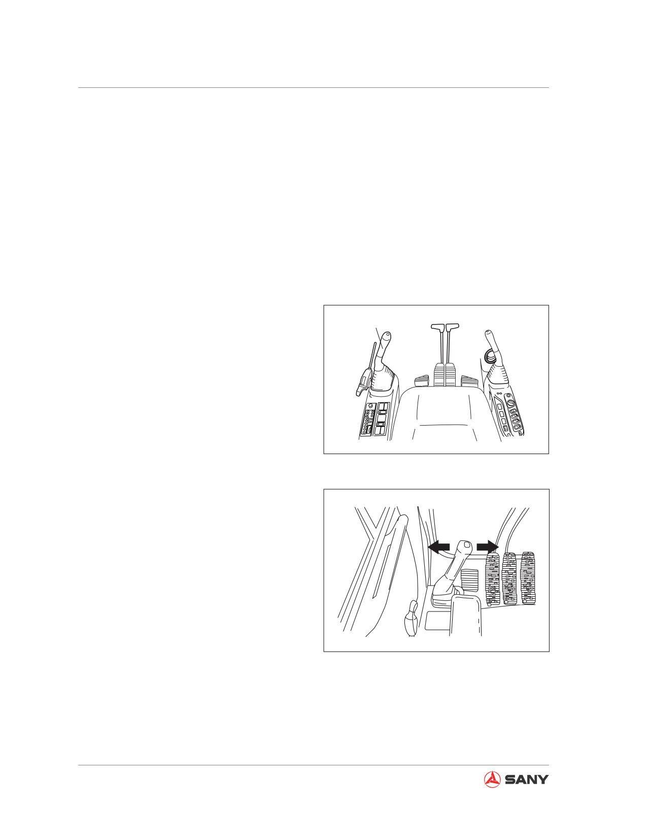
4.4.1 Before moving the machine
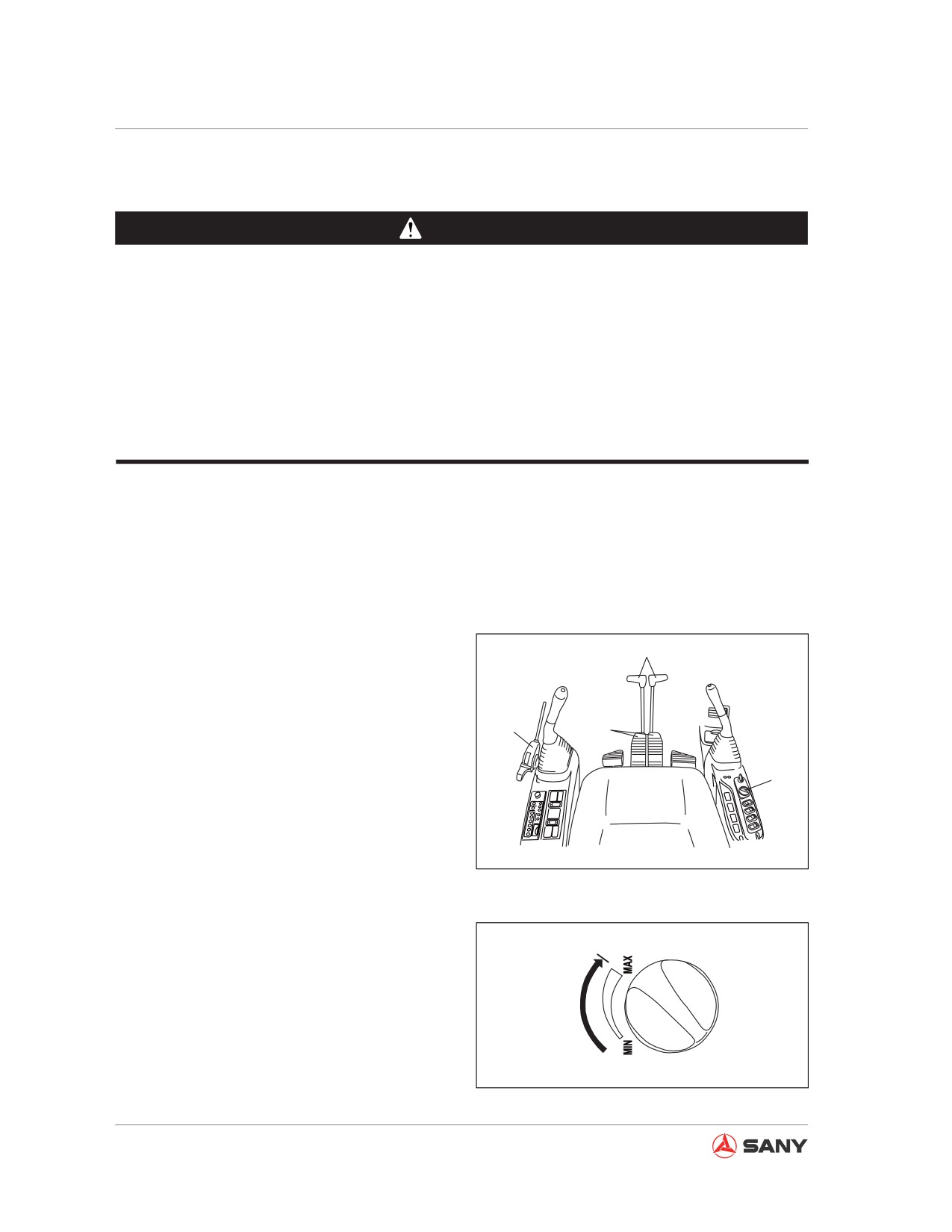
3
(1) Fuel control dial
(2) Hydraulic lockout control
2
4
(3) Travel control levers
(4) Travel control pedals
1
CZ335-1103161
Fig. 4-44
Turn the fuel control dial in the MAX direction
to the desired position in order to increase en-
gine speed.
CZ335-1103162
Fig. 4-45
4-28
Operation
4.4.2 Moving the machine forward
1.
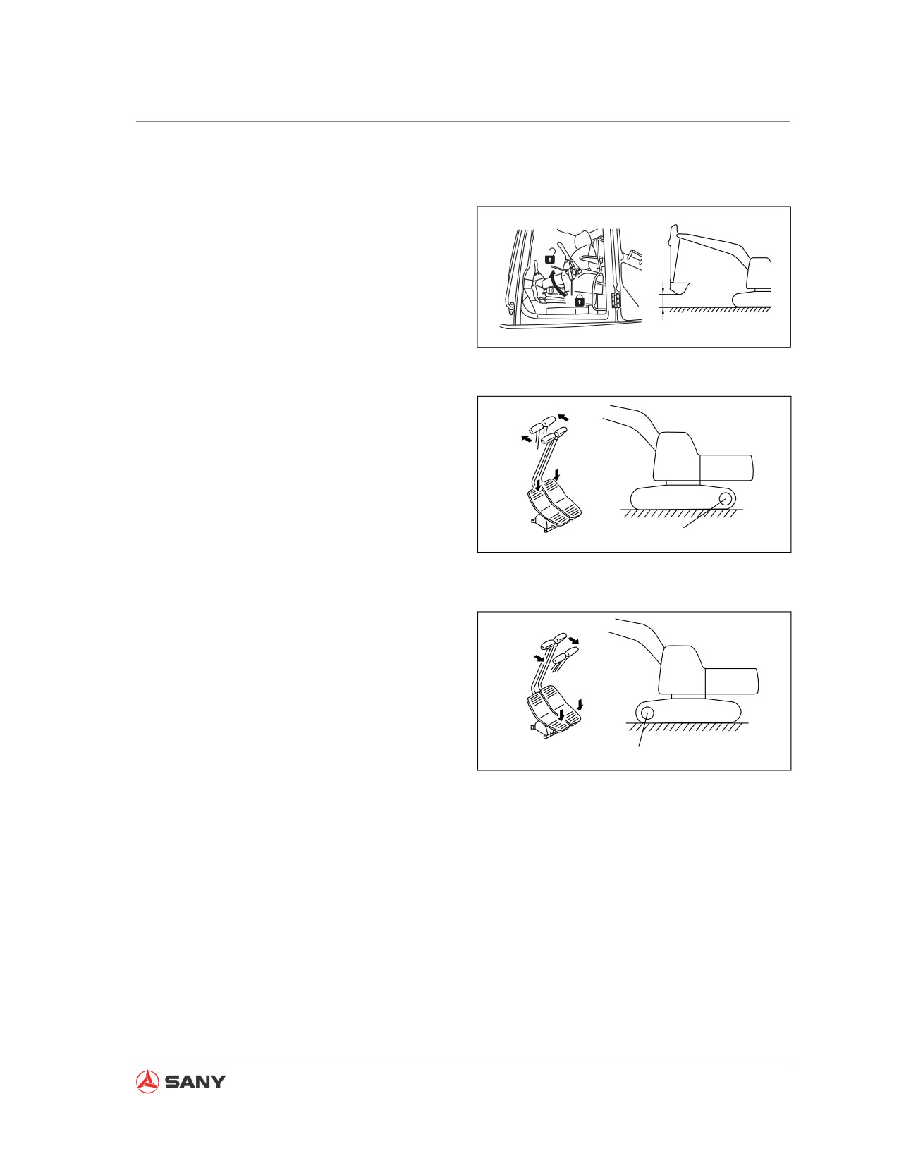
Place the hydraulic lockout control to the
FREE position (F), and retract the work
equipment till it is 40-50 cm above the
F
ground, as shown in the right illustration.
L
●
If you never have a good visibility to the
right, raise the boom to ensure a good vis-
40~50cm
CZ335-1103163
ibility.
Fig. 4-46
2.
Operate the left and right travel control
levers or the left and right travel pedals
according to the following instruction:
●
When the sprocket (A) is under the rear
part of machine:
Slowly push the control lever or slowly
A
CZ335-1103164
push down the front part of pedal to move
the machine.
Fig. 4-47
●
When the sprocket (A) is under the front
part of machine:
Slowly pull the control lever or slowly push
down the rear part of pedal to move the
machine.
A
CZ335-1103165
Fig. 4-48
Remark:
Fully preheat your machine if its travel speed
is abnormal in cold weather. In addition, if the
undercarriages is stuck with mud and the ma-
chine's travel speed becomes irregular, it is
necessary to remove the mud from the under-
carriage.
4-29
Operation
4.4.3 Moving the machine backward
1.
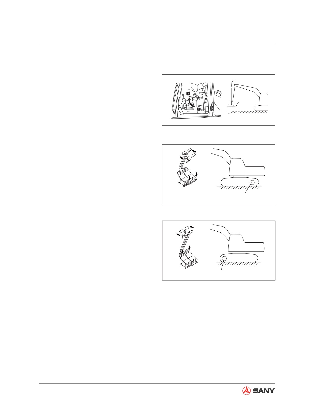
Place the hydraulic lockout control to the
FREE position (F), and retract the work
equipment till it is 40-50 cm above the
F
ground, as shown in the right illustration.
L
●
If you never have a good visibility to the
right, raise the boom to ensure a good vis-
40~50cm
CZ335-1103163
ibility.
Fig. 4-49
2.
Operate the left and right travel control
levers or the left and right travel pedals as
the following:
●
When the sprocket (A) is under the rear
part of machine:
Slowly pull the control lever or slowly push
A
down the rear part of pedal to move the
CZ335-1103166
machine backward.
Fig. 4-50
●
When the sprocket (A) is under the front
part of machine:
Slowly push the control lever or slowly
push down the front part of pedal to move
the machine backward.
A
CZ335-1103167
Fig. 4-51
Remark:
Fully preheat your machine if its travel speed
is abnormal in cold weather. Moreover, if the
tracks are stuck by mud and the machine's
travel speed becomes irregular, it is necessary
to remove the mud from the tracks.
4-30
Operation
4.4.4 Parking the machine
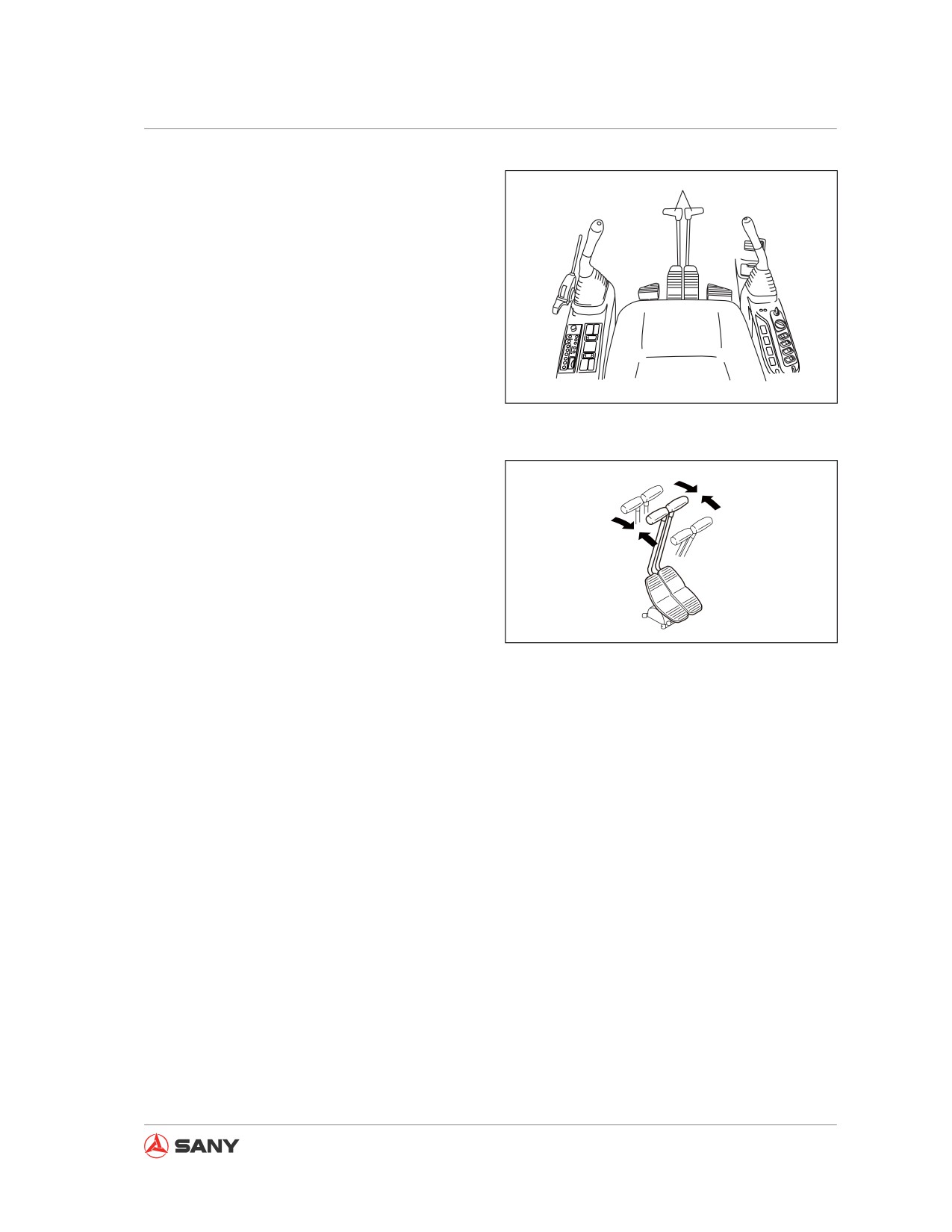
1
Never park your machine suddenly.
Before parking your machine, leave yourself
enough space so that you could leave the ma-
chine easily.
Place the left and right travel control levers
(1) to neutral position before parking your ma-
chine.
CZ335-1103168
Fig. 4-52
N
N
CZ335-1103169
Fig. 4-53
4-31
Operation
4.5 Steering Operation
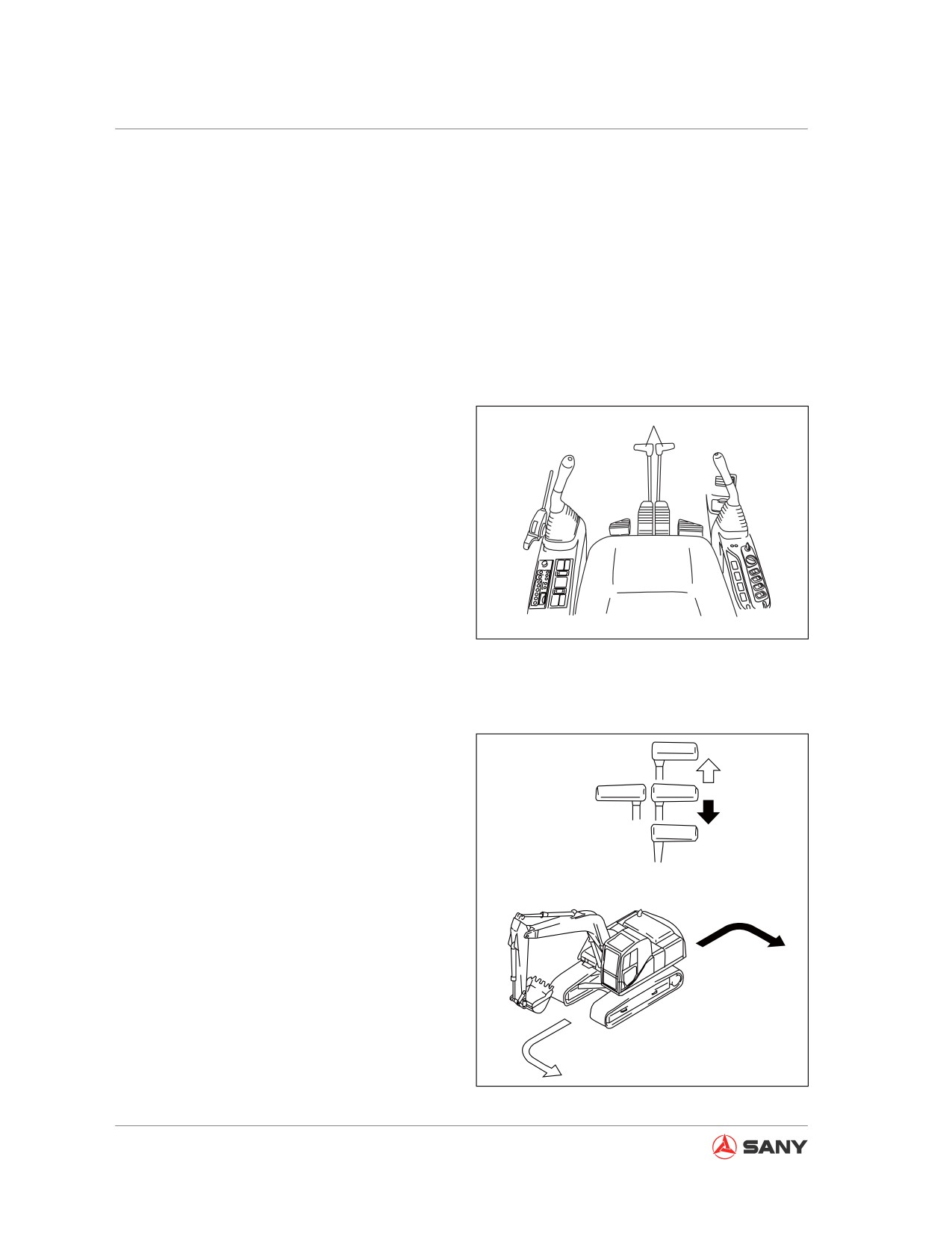
Check the direction of track frame (position of
sprocket) before maneuvering the travel con-
trols. When the operator faces the sprockets,
moving direction of travel controls is opposite
to travel direction of machine.
4.5.4.1 Steering with travel controls
Avoid changing travel direction suddenly if
1
possible. Stop your machine before making a
turn, especially before a pivot turn.
Operate travel controls (1) according to the
following instructions.
CZ335-1103168
Fig. 4-54
4.5.4.2 Steering with machine stopped
When turning to the left side:
A
Push the right travel control lever to turn the
machine to the left side in forward travel.
B
Pull the right travel control lever to turn the
machine to the left side in backward travel.
(A) Turning left in forward travel
(B) Turning left in backward travel
Remark:
Operate the left travel control lever in the
same way to turn your machine to the right
side.
CZ335-1103170
Fig. 4-55
4-32
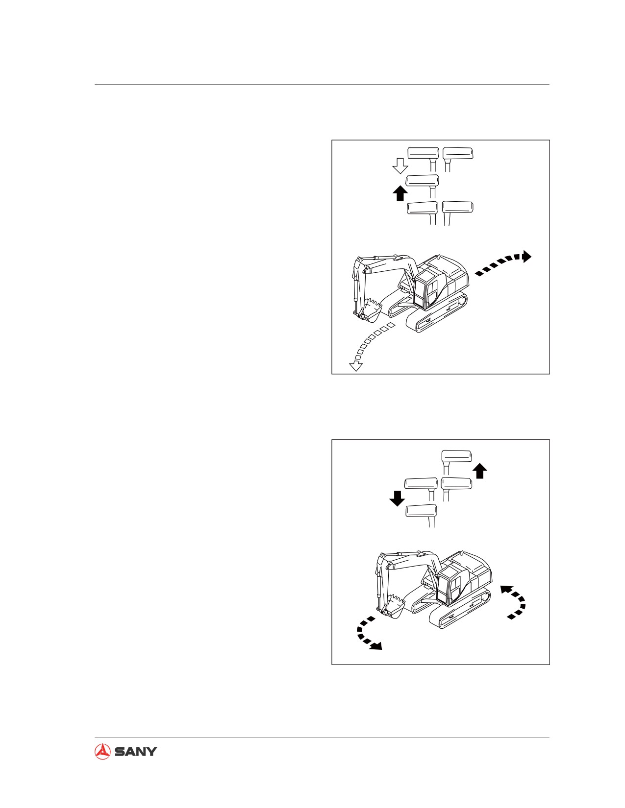
Operation
4.5.4.3 Steering during traveling
When turning to the left side:
A
Place the left travel control lever in the neutral
position to turn your machine to the left side
during traveling.
B
(A) Turning left during forward travel
(B) Turning left during backward travel
Remark:
Operate the right travel control lever in the
same way to turn your machine to the right
side during traveling.
CZ335-1103171
Fig.
4-56
4.5.4.4 Pivot turn
Pull the left travel control lever and push the
right one to make a pivot turn to the left side.
Remark:
Pull the right travel control lever and push the
left one to make a pivot turn to the right side.
CZ335-1103172
Fig. 4-57
4-33
Operation
4.5.1 Swing operation
● When the rear part of the machine is posi-
tioned away from the track, check whether
the surrounding area of the machine is
safe before carrying out swinging opera-
tion.
● When the engine's speed decreases due
to automatic idling function, the engine's
speed could increase abruptly if any con-
trol lever is maneuvered. Be careful with
the operation of control levers.
Maneuver the left joystick (1) in the illustrated
1
directions to swing the turntable of upper
structure.
(A) Swing to left
(B) Swing to right
CZ215-1103064
Fig. 4-58
A
B
CZ335S-1103067
Fig. 4-59
4-34
Operation
4.6 Work Equipment Control and
Operation
CAUTION
Operation of the control levers while the
engine is idling may cause engine speed
to increase abruptly. Be careful with the
operation of joystick controls.
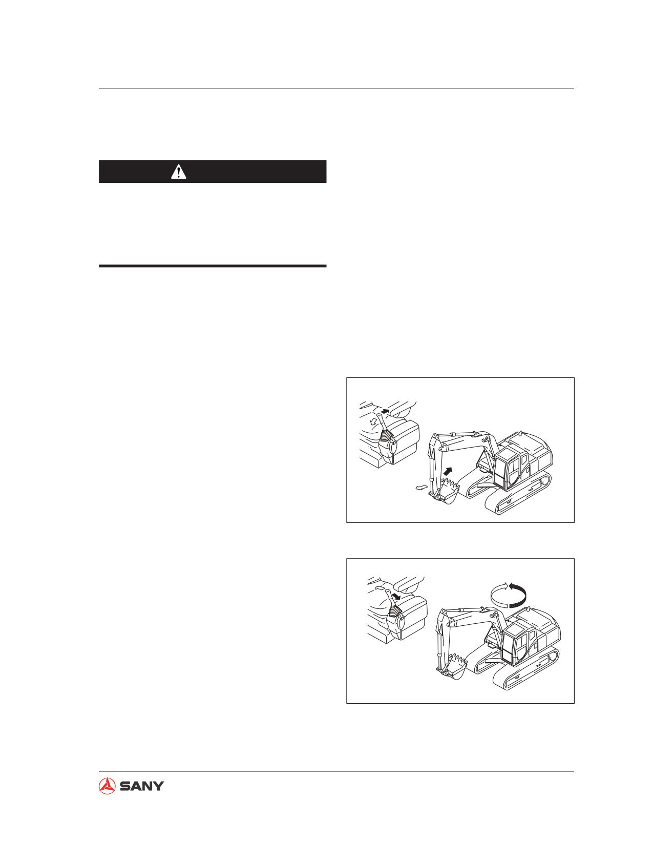
Work equipment is controlled through the joy-
sticks.
Note that joystick control will return to neutral
position when released and movement of work
equipment will be held.
● Arm control
Push or pull the left joystick to control arm op-
eration.
CZ335-1103175
Fig. 4-60
● Swing control
Move the left joystick left or right to control
swing operation.
CZ335-1103176
Fig. 4-61
4-35
Operation
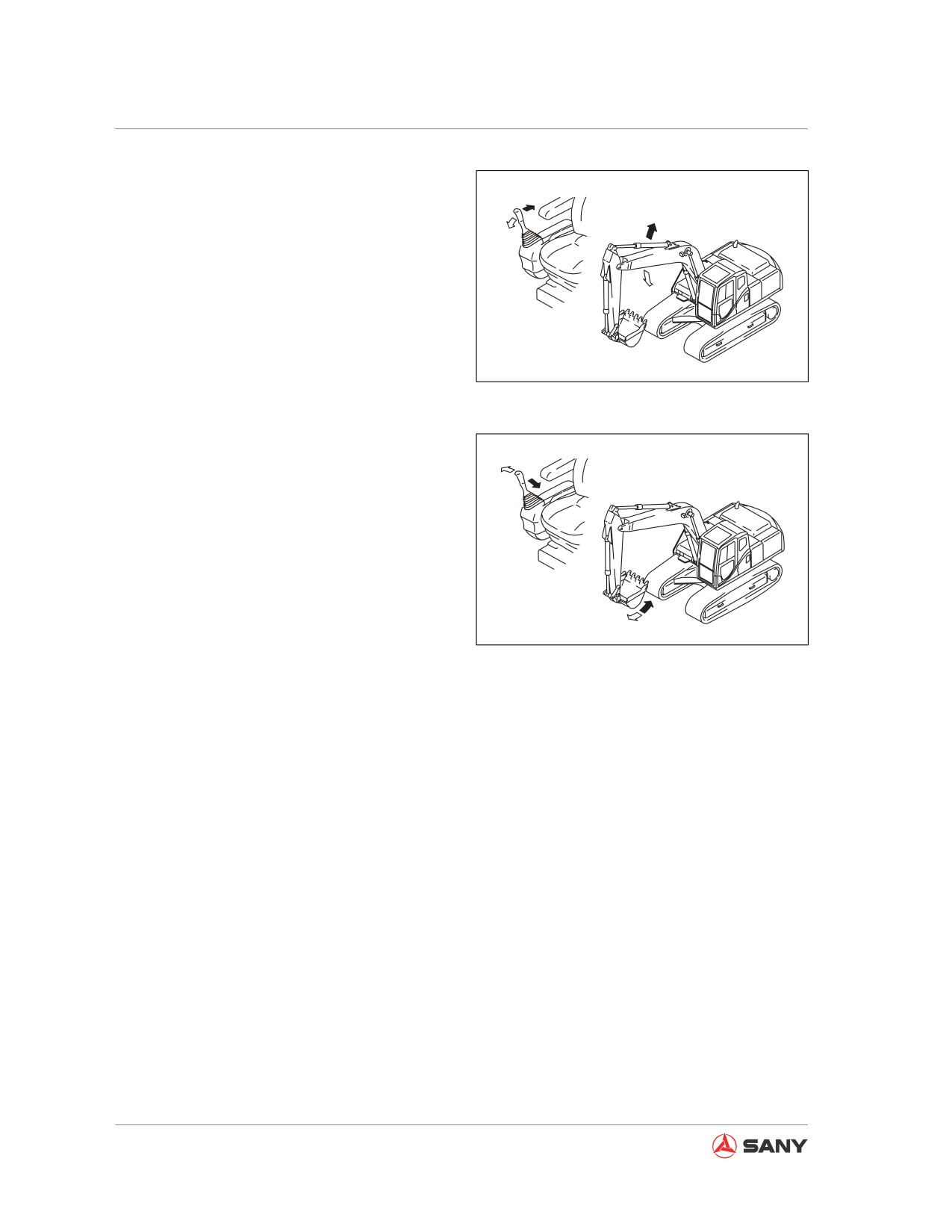
● Boom control
Push or pull the right joystick to control boom
operation.
CZ335-1103177
Fig. 4-62
● Bucket control
Move the right joystick left or right to control
bucket operation.
When joystick control is in the neutral position,
the auto deceleration system will be activated
to lower engine speed to a moderate level if
no operation is performed within 5 seconds.
This will happen even if you turn the fuel con-
CZ335-1103178
trol dial to the MAX position.
Fig. 4-63
Remark:
This machine includes an energy accumulator
installed in oil control lines. Turning the start
switch key to ON position and placing the hy-
draulic lockout control to the FREE position,
within 15 minutes after shutting off the engine,
allows you to maneuver the control levers to
lower the work equipment to ground.
This method can also be used to release the
remaining pressure of hydraulic system, or to
lower the boom after the machine has been
loaded onto a trailer.
4-36
Operation
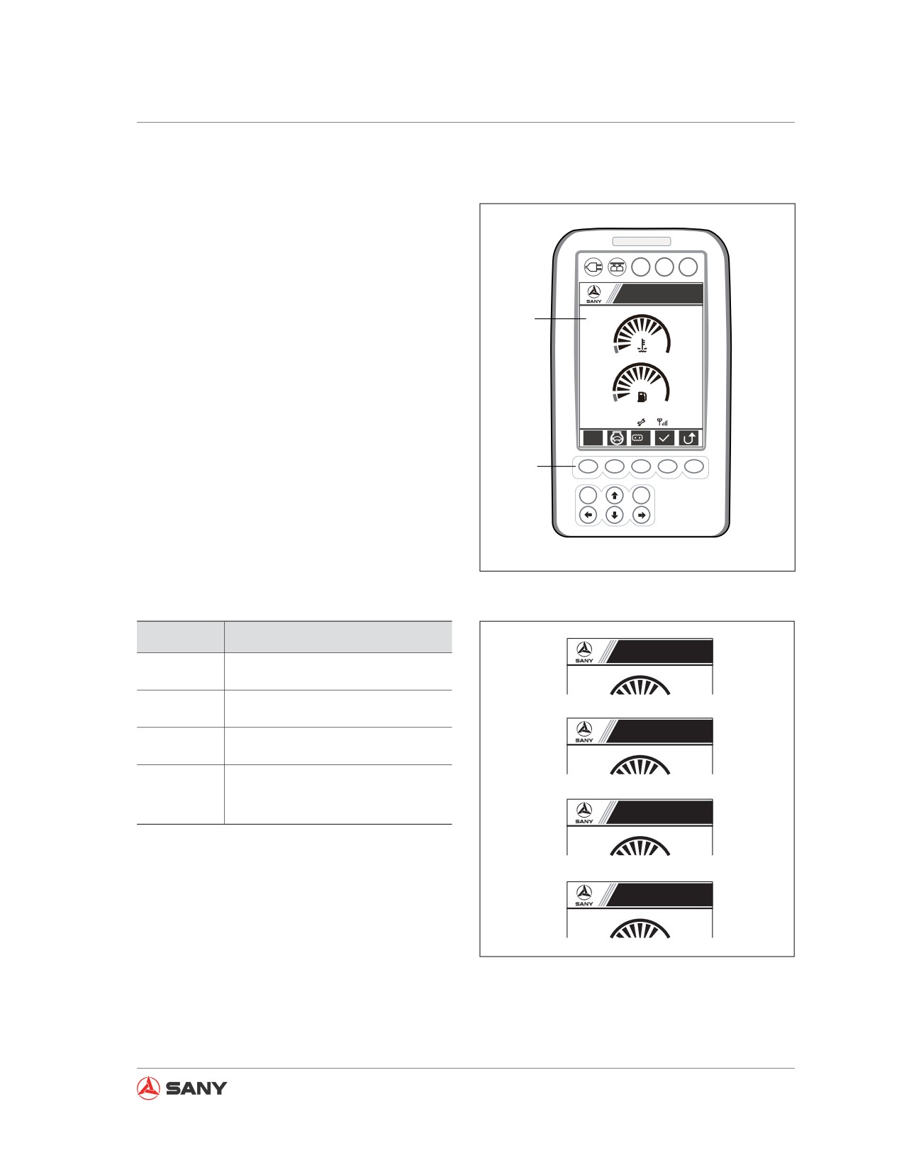
4.7 Working mode
The working modes selection switch (1) is
used to select a mode suitable for your work-
ing condition and purpose. In this way, effec-
tive operation can be achieved.
A B C
Sany Hydraulic Excavator
Select the most effective working modes
2
S
1
through the following steps:
● Default working modes H will be displayed
when the start switch is ON.
● Working modes selection key F1 is used to
09/03/05
0000h 00m
12
12:25:31
set the optimum mode according to operat-
S
Lo
ing practices.
1
F1
F2
F3
F4
F5
When pressing down the working modes
ESC
Enter
selection key (1), the working modes will be
cycled (H → S → L → B) at (2) on the screen.
CZ135-1103003
Fig.
4-64
Mode
Suitable Operations
Sany Hydraulic Excavator
Heavy-loaded operation for such
H
as ore excavation
H
5
Standard operation for such as
S
earth removing
Sany Hydraulic Excavator
Breaking operation performed
B
with breaker
S
5
Light-loaded operation for level-
L
ing ground or trimming a slope.
Sany Hydraulic Excavator
B
5
Note:
If breaking operation is performed in a mode
Sany Hydraulic Excavator
other than mode B, the hydraulic unit could be
L
5
damaged.
CZ215-1103053
Never perform breaking operation in a mode
Fig.
4-65
other than mode B.
4-37
Operation
4.8 Restricted Operations
● Never maneuver the control levers of the
work equipment when the machine is trav-
eling. Stop the machine before maneuver-
ing any control lever.
● The engine's speed could increase abrupt-
ly if you maneuver any control lever when
the automatic idling function is active.
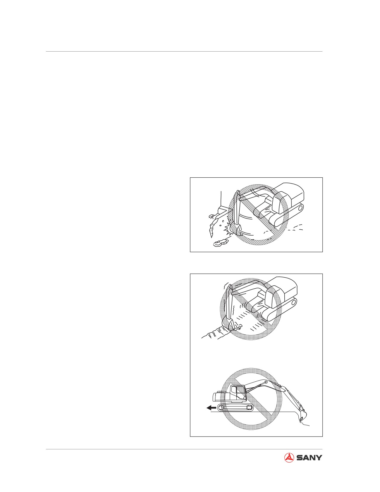
4.8.1 Operation with swinging force
Never use the swinging force to compact the
ground or break objects. Doing this is danger-
ous. In addition, the service life of machine
would be reduced considerably.
CZ335-1103181
Fig. 4-66
4.8.2 Operation with traveling force
Never cut your bucket into ground and use the
traveling force to excavate, which could dam-
age your machine or work equipment.
CZ335-1103182
Fig. 4-67
4-38
Operation
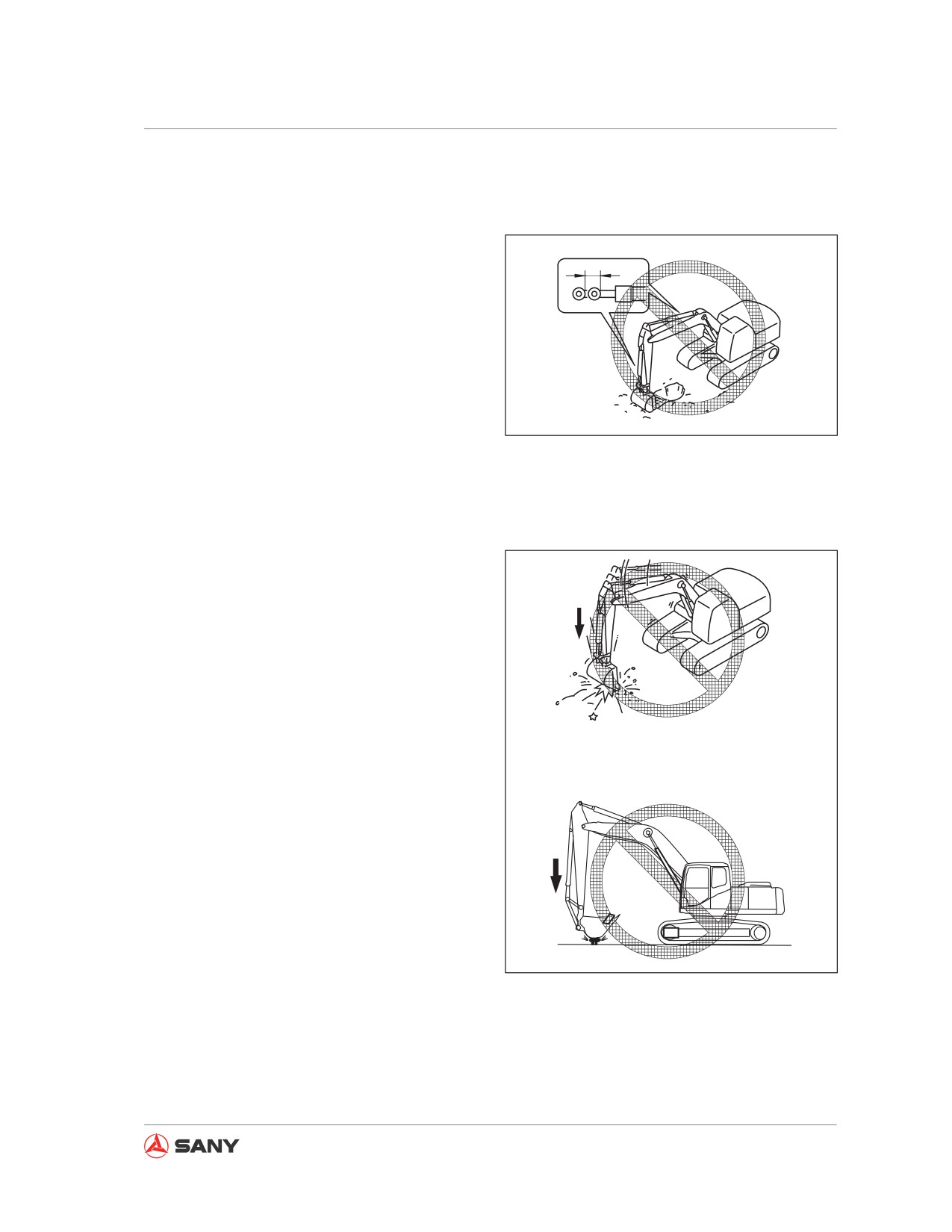
4.8.3 Operation when hydraulic cylin-
der reaches its stroke end
If the cylinder's piston reaches its end of
stroke, using the work equipment under ex-
ternal impact could damage hydraulic cylinder
and cause personal injury. Avoid operating the
machine when its hydraulic cylinder is fully re-
tracted or extended.
CZ335-1103183
Fig. 4-68
4.8.4 Operation with bucket landing
force
1. Never use the bucket's landing force for
excavating, digging, breaking or pile-driving
operation, which may otherwise reduce the
service life of the machine considerably.
2. To avoid damage of hydraulic cylinders,
never use the bucket to strike or compact
the ground while its cylinder is fully ex-
tended or retracted.
CZ335-1103184
Fig. 4-69
4-39
Operation
4.8.5 Operation with machine weight
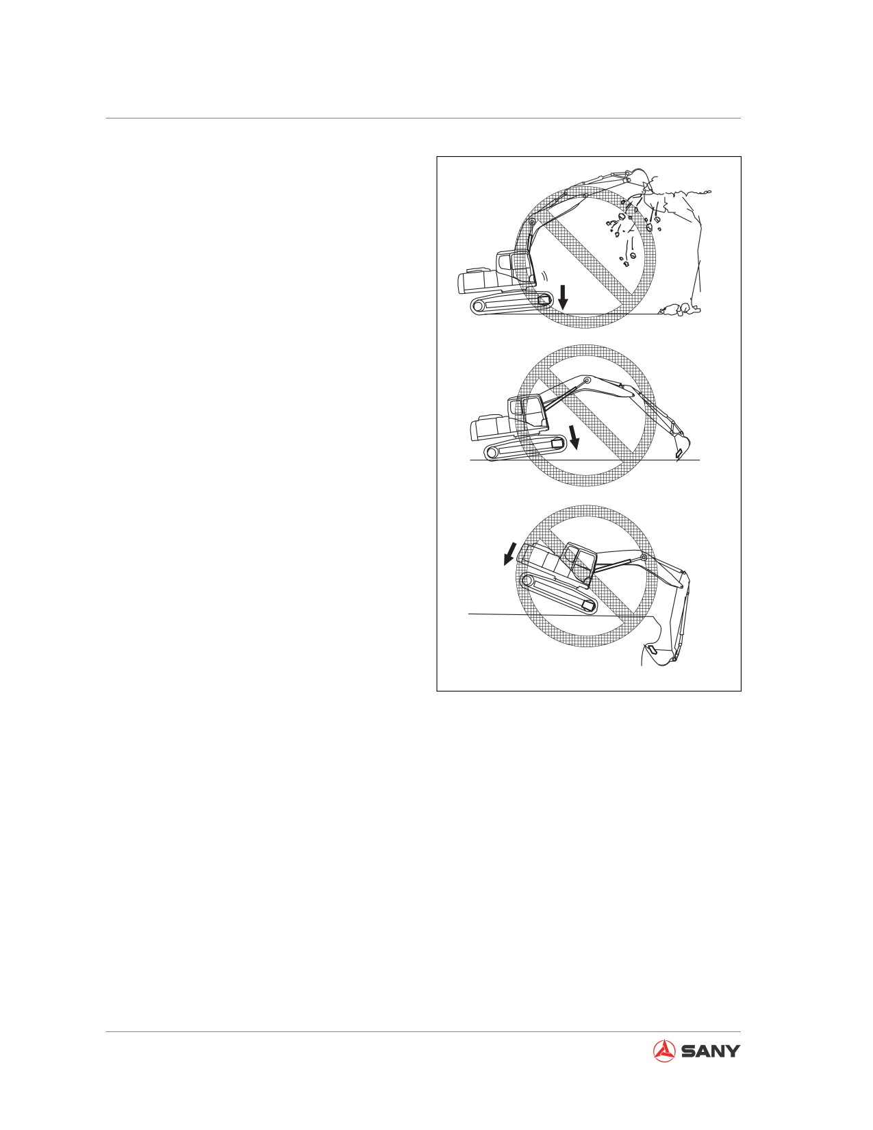
Never use the weight of machine to excavate.
CZ335-1103185
Fig. 4-70
4.8.6 Hard rocky ground
Never try to directly excavate hard rocky
ground. Perform excavation after breaking the
rocks through other means. By doing so, dam-
age to your machine could be minimized, in
addition to cost reduction.
4-40
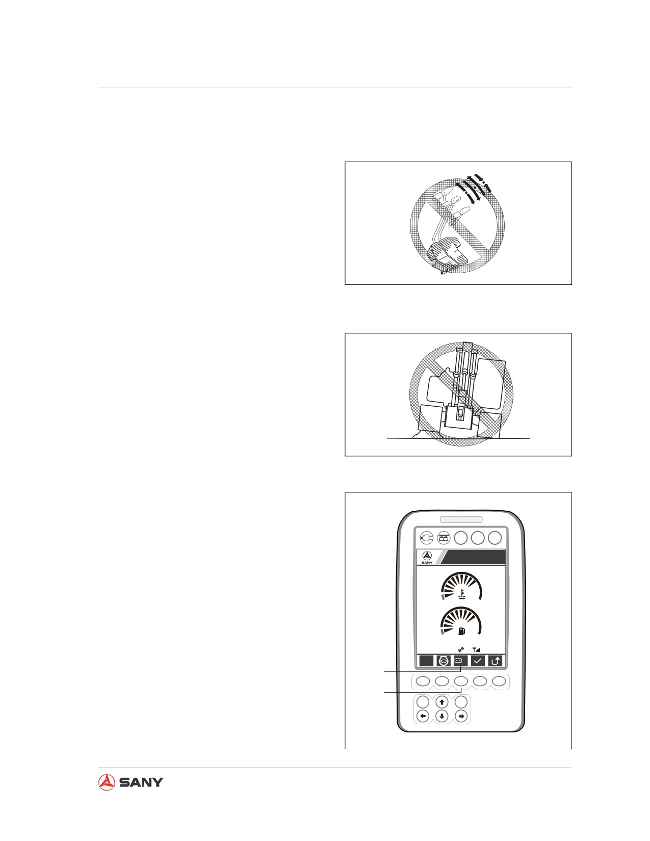
Operation
4.8.7 Sudden shift of travel speed dur-
ing fast traveling
1. Never maneuver any control lever or pedal
abruptly to change the action of machine.
A
3
2
2. Never suddenly change the position of
1
control lever or pedal from forward (A) to
B
reverse (B), or vice versa.
3. Never stop the machine by suddenly
CZ335-1103186
releasing the control lever or pedal while
traveling at high speed.
Fig. 4-71
4.9 General Operation
4.9.1 Traveling operation
Traveling over road shoulders, stumps or other
barriers could bring strong impact on the chas-
sis (especially the tracks), and cause damage
CZ335-1103187
to the machine. In this case, remove the bar-
riers or bypass them. You can also take other
Fig.
4-72
actions to avoid barriers.
If there is no way to avoid traveling over barri-
ers, drive your machine slowly while keeping
its work equipment close to ground and run-
A B C
ning the track over barriers along the track's
Sany Hydraulic Excavator
centerline.
S
1
4.9.2 High-speed travel
Run your machine slowly on rough surfaces
09/03/05
with rocky bed or large stones. Place the ten-
0000h 00m
12
12:25:31
S
Lo
sion wheel in forward direction while traveling
2
at high speed.
F1
F2
F3
F4
F5
1
ESC
Enter
● Press F3 (1) to change the travel speed.
The travel speed (Hi or Lo) will be dis-
played at (2) above the F3 key.
CZ135-1103004
Fig. 4-73
4-41
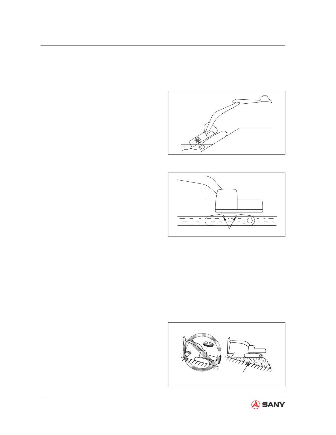
Operation
4.9.3 Permissible depth of water
Note:
When driving your machine out of water, an
inclination of slope exceeding 15° would have
the rear of its upper turntable immersed in
water, thus the fan could be damaged due to
water.
Pay special attention to your machine when
driving it out of water.
CZ335-1103189
● Don not drive your machine into water
Fig. 4-74
where water level could reach the center of
carrier roller (1).
● Add grease to parts that have been soaked
long in water, till old grease is completely
squeezed out of the bearing (especially the
area around the pin of bucket).
● Never operate your machine in water un-
less the foundation of job site is strong
enough so that the level of water could not
1
CZ335-1103190
reach the center of carrier roller.
Fig. 4-75
● If the swing bearing, swing gear and cen-
tral swing joint are soaked in water, the
drain plug should be opened to remove
mud and water. Clean the swinging area
and reinstall the plug. Lubricate the mesh
gear and swing bearing inside the swing
unit.
4.10 Traveling on Slope
● When operating your machine on a slope,
never turn your machine or operate the
work equipment as that would cause your
machine to loose balance.
● It is dangerous to swing downward on a
slope when your bucket is loaded. If such
operation is necessary, you have to pile
Platform
up a platform on the slope with earth so
CZ335-1103191
that your machine could be kept on a level
ground.
Fig. 4-76
4-42
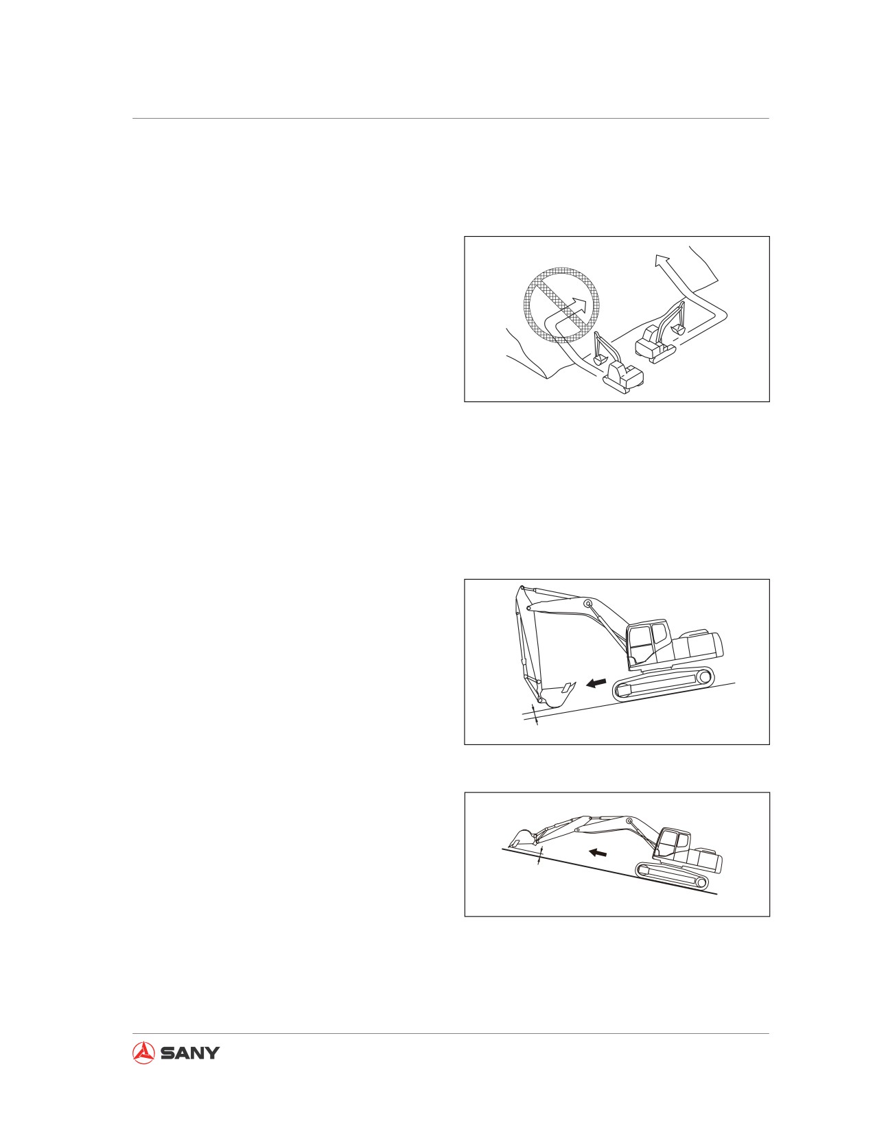
Operation
●
Never travel on a steep slope, which could
cause your machine to tip over.
●
The bucket must be lifted 20-30 cm above
the ground during traveling.
●
Never travel reversely down a slope.
●
Never turn your machine on a slope or tra-
verse a slope.
●
The above operations must be carried out
on a level ground. You might have to travel
a long distance for the sake of safety.
●
The operations must be performed in this
CZ335-1103192
way because the machine can be stopped
Fig. 4-77
safely at any time when it skids or be-
comes instable.
●
If the track shoes skid or the power of
tracks is unable to help your machine run
up a slope, never use the pulling force of
arm to run up the slope as that could dam-
age your machine.
1.
The travel control lever and fuel control dial
are used to keep your machine traveling at
a low speed when running down a steep
slope. When angle of the slope is more
than 15°, adjust your work equipment to
an attitude as shown in the right illustration
and lower engine speed.
20~30cm
CZ335-1103193
2.
When running up a steep slope, it is
necessary to move your work equipment
Fig. 4-78
to the forward direction. Maintain the work
equipment at about 20-30 cm above the
ground and travel at a low speed.
20~30cm
CZ335-1103194
Fig. 4-79
4-43
Operation
4.10.1 Traveling downhill
Place the travel control levers to the neutral
position, which can make the brake function
automatically.
4.10.2 Engine stalls on an incline
If the engine stops while traveling on a slope,
place the travel control lever to its neutral po-
sition, lower the bucket to the ground and park
the machine before restarting the engine.
4.10.3 Cab door on an incline
● If the engine stalls out on a slope, never
perform swinging operation with the left
joystick. The upper turntable will swing
naturally under its weight.
● When your machine is on a slope, never
open or close the cab door, which can
change suddenly the force on machine.
Always keep the cab door in an opening or
closing position.
4.11 Removing Machine from Mud
Be careful with operation and avoid being
trapped in the mud. If your machine is trapped
in the mud, drive it out according to the follow-
ing method.
4.11.1 One track trapped
Note:
When the boom or arm is used to lift your ma-
chine, make sure that the bottom of bucket
contacts the ground. The boom and arm shall
form an angle between 90 and 110°.
This is also applicable to a reversely-mounted
4-44
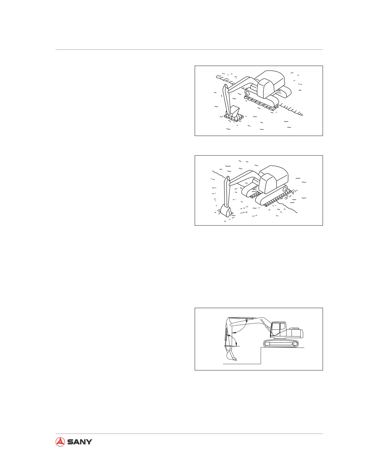
Operation
bucket.
When one of the tracks is trapped in the mud,
use the bucket to lift the track, place wood
planks or logs under the track and then drive
your machine out of the mud.
4.11.2 Both tracks trapped
CZ335-1103195
Fig.
4-80
When both tracks are trapped in the mud and
the machine cannot move due to skidding, use
wood planks as described in the above meth-
od and cut your bucket into the ground in front
of your machine. Retract the arm as you do
in normal excavation, place the travel control
lever in "FORWARD" position, and drive your
machine out.
CZ335-1103196
Fig.
4-81
4.12 Recommended Applications
Besides the following applications, the scope
of application could be expanded by using
various additional attachments.
4.12.1 Backhoe operation
Backhoe operation is suitable for digging an
area which is lower than your machine.
90°
When your machine is in a state shown in the
right illustration (the angle between (bucket
90°
cylinder and link) and (bucket cylinder and
arm) is 90°), maximum digging force can be
obtained through the thrusting force of each
CZ335-1103197
hydraulic cylinder.
Fig.
4-82
When digging, using this angle effectively can
help you achieve the maximum working effi-
ciency.
4-45
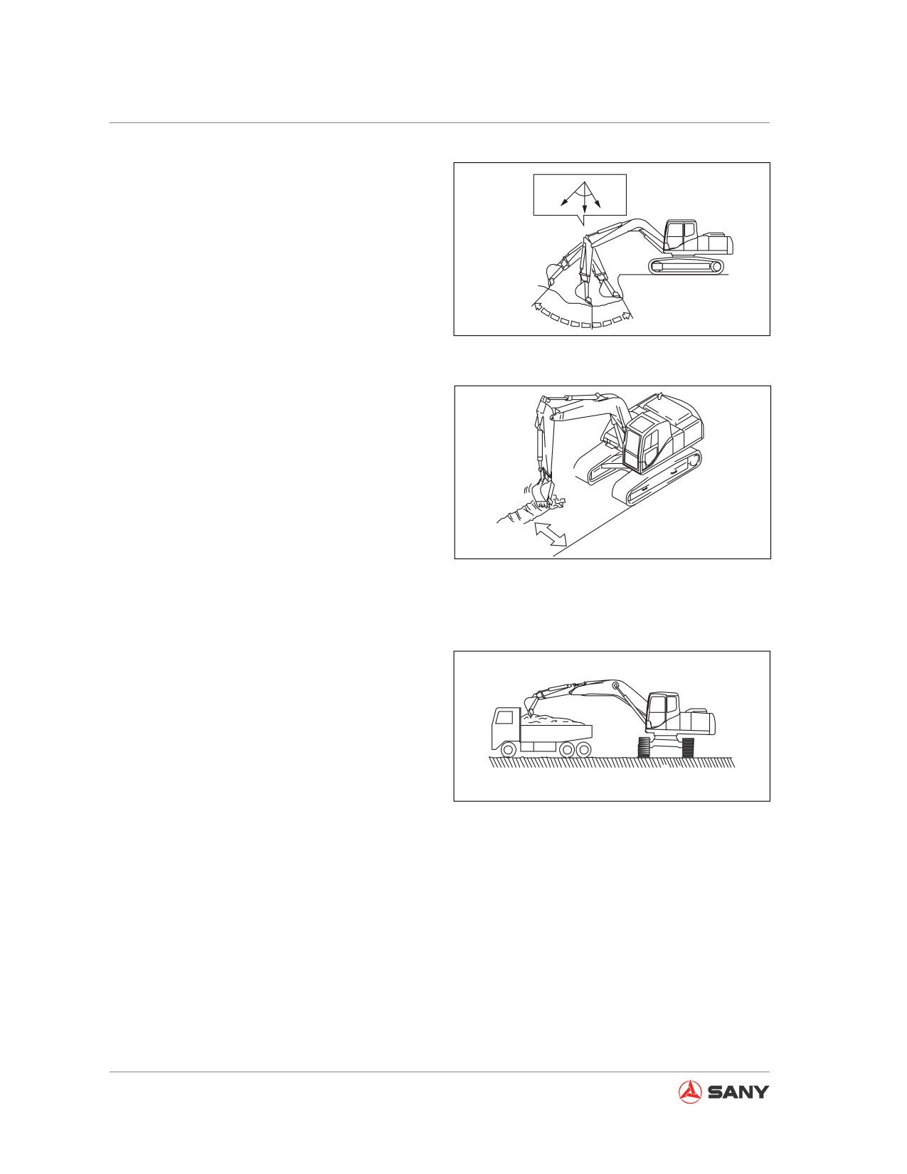
Operation
The digging range of arm is from 30 to 45°, as
45°
30°
relative to the machine.
The angle may vary according to digging
depth, but it is better to keep it within the
above range if possible. Never operate the hy-
draulic cylinders to their full stokes.
CZ335-1103198
Fig. 4-83
4.12.2 Trench work
You can dig a trench efficiently by installing
a bucket suitable for this job and adjust your
tracks to parallel the to-be-dug trench line.
When digging a wider trench, excavate first
Parallel
both sides of the trench and then remove the
CZ335-1103199
middle part.
Fig. 4-84
4.12.3 Loading operation
In a place where the swinging angle is small,
working efficiency can be improved by parking
the dump truck at where the operator could
see easily.
It is more convenient to load more material if
the truck is loaded from rear rather than from
CZ335-1103200
its sides.
Fig. 4-85
4-46
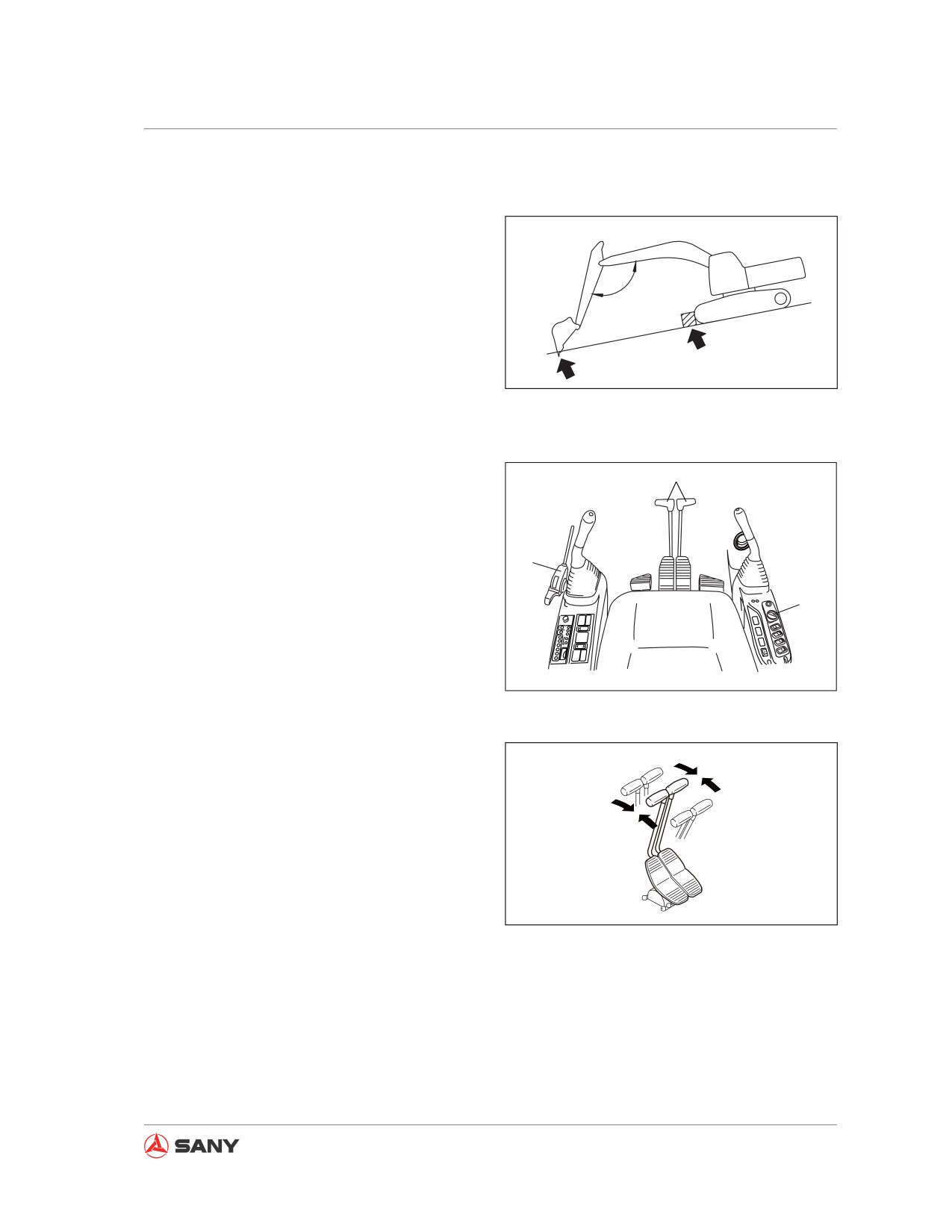
Operation
4.13 Parking Operation
Park your machine on a hard, level ground
that is free from dangers. If you have to park
your machine on a slope, chock the tracks
with blocks. You can also penetrate the bucket
120°
into ground as additional safety support.
If any of the control levers is moved unexpect-
edly, the machine may move suddenly and
CZ335-1103205
cause serious accidents. Make sure that the
hydraulic lockout control has been placed in
Fig. 4-86
"locked" position before you leave the cab.
1. Place both right and left travel control
1
levers (1) in neutral position to stop your
machine.
3
2
CZ215-1103065
Fig. 4-87
N
N
CZ335-1103169
Fig. 4-88
4-47
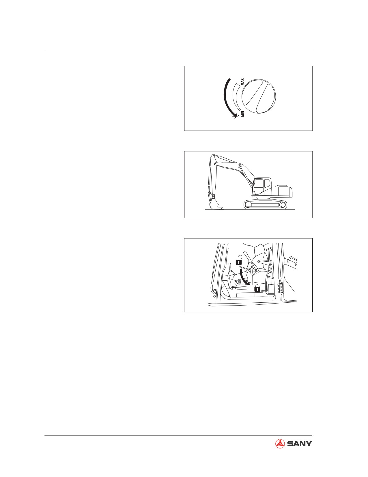
Operation
2. Turn fuel control dial to low idle (MIN) posi-
tion in order to reduce engine speed.
CZ335-1103153
Fig. 4-89
3. Lower the bucket horizontally until its bot-
tom is in contact with ground.
CZ335-1103207
Fig. 4-90
4. Place hydraulic lockout control in LOCK
position (L).
F
L
CZ335-1103149
Fig. 4-91
4-48
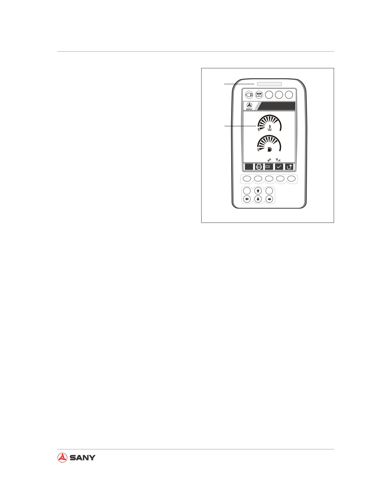
Operation
5. Check engine coolant temperature and oil
pressure on machine monitor.
1
● If red segments appear on coolant tem-
A B C
perature gauge (2), cool down the engine
Sany Hydraulic Excavator
until red segments disappear. Shut down
S
1
the engine.
2
● If alert indicator (1) is on and you are sure
it is caused by abnormal oil pressure, shut
down the engine immediately.
09/03/05
6. Shut down the engine. For engine shut-
0000h 00m
12
12:25:31
S
Lo
down steps see “Engine Shutdown”
on page 4-27.
F1
F2
F3
F4
F5
ESC
Enter
CZ135-1103005
Fig. 4-92
4.14 Checks after Each Workday
1. Inspect your machine and check the work
equipment, the exterior of machine, and
the undercarriage. Check for leaks of oil or
coolant. Repair it in case of any problem.
2. Refuel the tank to maximum level.
3. Check the engine compartment for any
paper or other debris. Remove them, if
any, in order to prevent fire.
4. Remove mud built up on the undercar-
riage.
5. If the ambient temperature is below -35°C,
make sure to drain the coolant of radiator
and engine (Sany uses the type of anti-
freeze liquid that freezes at -35°C. )
4-49
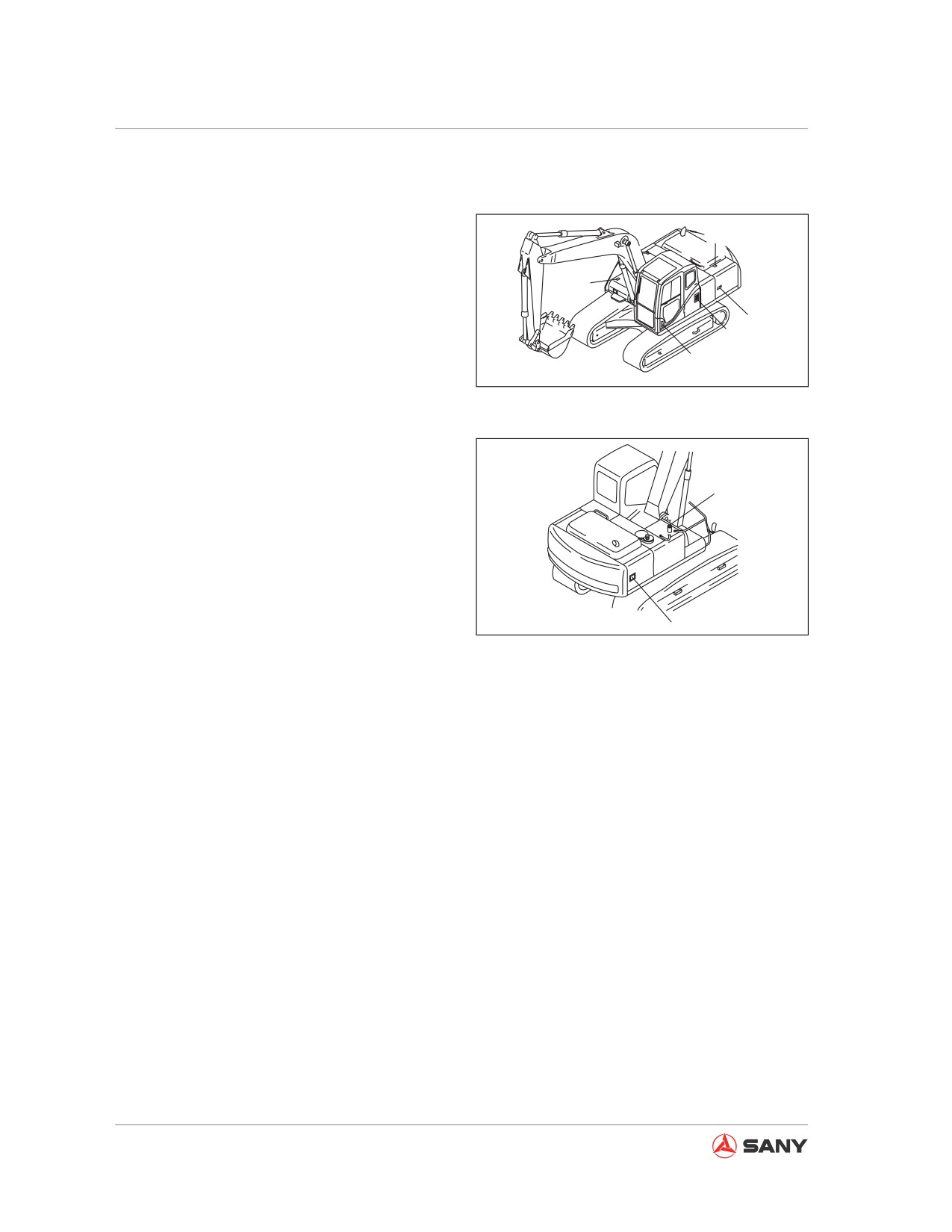
Operation
4.15 Locking the Machine
The following locations must be locked.
3
(1) Cab door
Close the windows properly.
4
(2) Injection cap of fuel tank
5
(3) Engine hood
7
(4) Battery cover (Battery is mounted behind
1
CZ335-1103208
left access door on some models.)
Fig. 4-93
(5) Left door of machine
(6) Right door of machine
(7) A/C fresh air inlet
2
Remark:
Use start switch key to lock and open these
locations.
6
CZ335-1103209
Fig. 4-94
4.16 Operation in Cold Weather
4.16.1 Operation instruction
The engine possibly fails to start and the cool-
ant may freeze under low temperature. In this
case, the following instructions must be fol-
lowed.
4.16.1.1 Fuel and lubricant
Fuel and lubricant with low viscosity shall be
used for all components.
For more information on specification of vis-
cosity se“Recommended Fluids”on page 5-17.
4-50
Operation
WARNING
● Antifreeze liquid is poisonous. Pay at-
tention to not letting it contaminate
your eyes or skin. If it contaminates
your eyes or skin, flush with large
amount of clean water and See medical
care immediately.
● When replacing the coolant or dispos-
ing the coolant containing antifreeze
liquid, which is drained when repairing
the radiator, contact your Sany dis-
tributor or a professional company to
dispose it. Since the antifreeze liquid
is poisonous, never drain it to sewage
system or leave it on the ground.
● Antifreeze liquid is flammable, so no
naked fire is allowed to approach it.
Never smoke while disposing antifreeze
liquid.
Note:
Please use Sany genuine, efficient anti-freeze
liquid as the coolant. In principle, we never
recommend you choosing any other type of
coolant.
See“Cooling system - clean”on page 5-37
for more information about the mixing ratio of
anti-freeze liquid when changing the coolant.
4.16.1.2 Battery
Battery capacity decreases as the ambient
temperature drops. It is important to keep bat-
tery capacity at 100% level. Never let the bat-
tery stay long under low temperature so as to
avoid the difficulty in starting your machine.
Since the battery's capacity will decrease un-
der low temperature, it is important to cover
the battery or remove it from your machine.
Store your battery in a warm place and rein-
stall it before operating your machine.
4-51

Operation
4.16.2 After each workday
CAUTION
Rotating track can cause severe injury.
Always keep a safe distance from rotating
track.
Observe the following precautions to prevent
the machine from being immobilized the next
day due to frozen mud and ice on the under-
carriage.
●
Remove all mud and water from your ma-
chine. Clean especially the piston rods of
hydraulic cylinders in order to prevent mud,
dirt or water from penetrating the cylinders
and spoiling the seals.
●
Park your machine on a hard, level ground.
Park your machine on planks if possible.
The planks can prevent your machine from
freezing with the ground and you can move
your machine the next day.
●
Open the drain valve to discharge accu-
mulated water of the fuel system so as to
prevent it from freezing.
●
Refill the fuel tank to the maximum level. In
this way, when ambient temperature drops,
the condensate in the tank could be mini-
mized.
●
After operation in water or mud, remove
the water on the undercarriage according
to the following instruction so as to extend
its service life.
1.
When the engine is running at idle speed,
swing the upper structure by 90° in order
to maintain the work equipment at the track
side.
2.
Lift one side of your machine just above
the ground, as shown in the illustration,
and run the track freely. Cycle this opera-
CZ335-1103210
tion between the left and right tracks.
Fig.
4-95
4-52
Operation
4.16.3 After cold season
When the season changes and the weather
gets warm, perform as described below.
● The fuel or lubricant of any components
shall be replaced with the one of specified
viscosity.
For more information see “Recommended
Fluids” on page 5-17 .
4-53
Operation
4.17 Long-Term Storage
4.17.1 Before storage
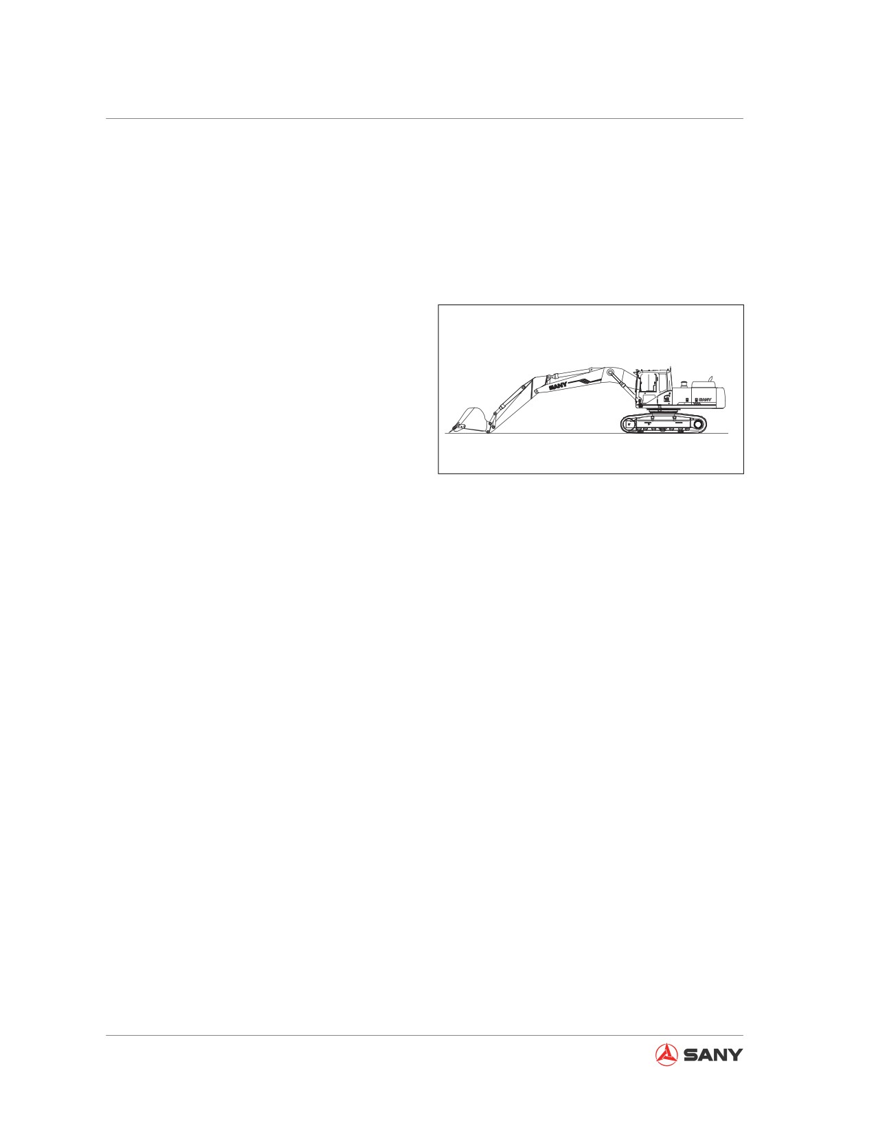
Note:
When storing your machine for more than one
month, adjust your machine to the attitude as
shown in the right illustration in order to pro-
tect cylinder piston rod against rusting.
When storing your machine for more than a
month, perform as described below:
●
Clean all parts of your machine and then
CZ335-1103211
store your machine indoors. If you have
Fig. 4-96
to store your machine outdoors, choose a
level ground and cover your machine with
canvas.
●
Refill your fuel tank to its maximum level in
order to avoid accumulation of water.
●
Lubricate your machine and change its oil
before storing it.
●
Apply grease to the exposed part of the
piston rod of hydraulic cylinder.
●
Disconnect the battery's negative terminal
and reinstall its cover, or remove the bat-
tery from your machine and store it in a
separate place.
●
For machines equipped with additional
equipment, the control pedal of additional
equipment shall be placed to LOCK posi-
tion.
●
To prevent rusting, please use Sany genu-
ine, efficient anti-freeze liquid as coolant of
the engine.
4-54
Operation
4.17.2 During storage
WARNING
When your machine is stored indoors, it is
important to prevent it from rusting, Open
the doors and windows to allow good ven-
tilation. This can also prevent gas poison-
ing.
● During storage, it is important to operate
your machine and drive it for a short dis-
tance once a month. This can help apply
a new oil film on parts and components.
Meanwhile, charge the battery of your ma-
chine. The storage temperature of this ma-
chine is between -25ºC and 75ºC.
● Before operating the work equipment, wipe
off all the grease from the piston rod of hy-
draulic cylinder.
● If your machine is equipped with air condi-
tioner, switch on the air conditioner for 3-5
minutes once a month, which can lubricate
all parts of its compressor. The engine shall
run at low idle speed when air conditioner
is working. In addition, check its refrigerant
twice a year.
4-55