SANY Crawler Hydraulic Excavator SY115C9, SY135C8, SY135C9, SY155H. Safety, Operation and Manitenance Manual - page 4
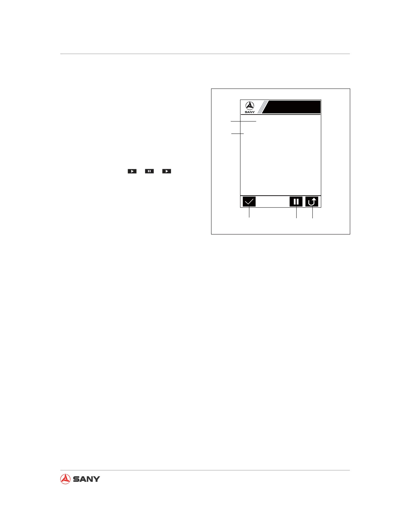
System Functions
Every 250 service hours
Screen output
Maintenance Information
1. Maintenance interval.
2. Maintenance items.
1
Every 250 Service Hours
① Replace the fuel filter element.
3. Press [F1] to call “System Setup”. Enter
2
② Clean the primary filter element of air
cleaner; check the secondary filter
the pass code and confirm that mainte-
element; replace all filter elements
when necessary.
nance is done.
③ Check the grease of swing system; add
grease to it when necessayr.
4. Press [F4] to start/pause rolling mainte-
④ Check the wear of work equipment pin
and bushing.
nance information:
→
→
……
⑤ Replace the return/pilot/suction filter
elements.
5. Press [F5] to return to the “Main Page”.
⑥ Check battery capacity.
⑦ Check the travel system and fill up gear
oil.
Keypad input
[F1]: Maintenance is OK.
3
4
5
XP1351106013
[F4]: Start/Pause rolling maintenance informa-
tion.
Fig. 3-18
[F5]: Return to the "Main Page".
[ESC]: Return to the "Main Page".
[Enter]: Maintenance is OK.
3-19
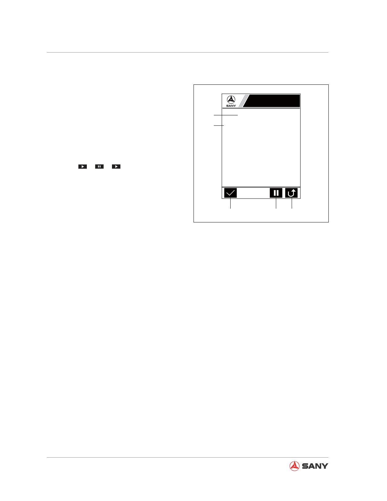
System Functions
Every 500 service hours
Screen output
Maintenance Information
1. Maintenance interval.
1
Every 500 Service Hours
2. Maintenance items.
① Perform maintenance for every 250 service
2
hours.
3. Press [F1] to call “System Setup”. Enter
② Clean the radiator (inside and outside).
③ Replace water separator filter element.
the pass code and confirm that mainte-
④ Grease the swing bearing.
⑤ Replace return/pilot/suction filter elements.
nance is done.
⑥ Replace air filter elements (internal and
external)
4. Press [F4] to start/pause rolling mainte-
⑦ Clean the screen of air conditioner.
⑧ Change the gear oil of swing system.
nance:
→
→
……
⑨ Change the gear oil of travel system.
⑩ Release the grease of track tensioner and
5. Press [F5] to return to the “Main Page”.
tension the track again.
Keypad input
[F1]: Maintenance is OK.
3
4
5
XP1351106014
[F4]: Start/Pause rolling maintenance informa-
tion.
Fig. 3-19
[F5]: Return to the "Main Page".
[ESC]: Return to the "Main Page".
[Enter]: Maintenance is OK.
3-20
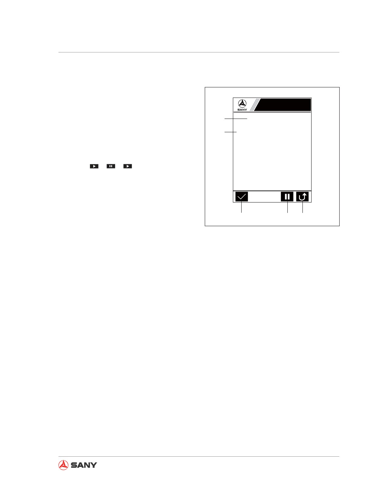
System Functions
Every 1000 service hours
Screen output
1. Maintenance interval.
Maintenance Information
2. Maintenance items.
1
Every 1000 Service Hours
① Perform maintenance for every 500
3. Press [F1] to call “System Setup”. Enter
2
service hours.
the pass code and confirm that mainte-
② Grease the swing system.
nance is done.
③ Replace the screen of air conditioner.
4. Press [F4] to start/pause rolling mainte-
nance:
→
→
……
5. Press [F5] to return to the “Main Page”.
Keypad input
[F1]: Maintenance is OK.
3
4
5
XP1351106015
[F4]: Start/Pause rolling maintenance informa-
tion.
Fig. 3-20
[F5]: Return to the "Main Page".
[ESC]: Return to the "Main Page".
[Enter]: Maintenance is OK.
3-21
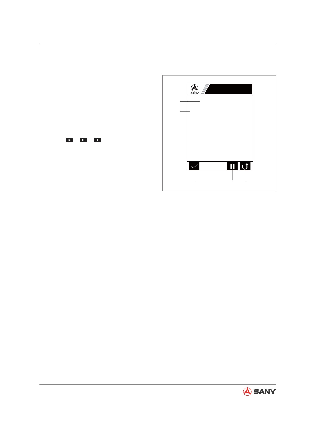
System Functions
Every 2000 service hours
Screen output
1. Maintenance interval.
Maintenance Information
2. Maintenance items.
1
Every 2000 Service Hours
3. Press [F1] to call “System Setup”. Enter
① Perform maintenance for every 1000
2
service hours.
the pass code and confirm that mainte-
② Check the engine, starter and bumper
nance is done.
rubber.
③ Change hydraulic oil, gear oil and
4. Press [F4] to start/pause rolling mainte-
coolant.
④ Lubricate swing bearing.
nance:
→
→
……
5. Press [F5] to return to the “Main Page”.
Keypad input
[F1]: Maintenance is OK.
3
4
5
XP1351106016
[F4]: Start/Pause rolling maintenance informa-
tion.
Fig. 3-21
[F5]: Return to the "Main Page".
[ESC]: Return to the "Main Page".
[Enter]: Maintenance is OK.
3-22
System Functions
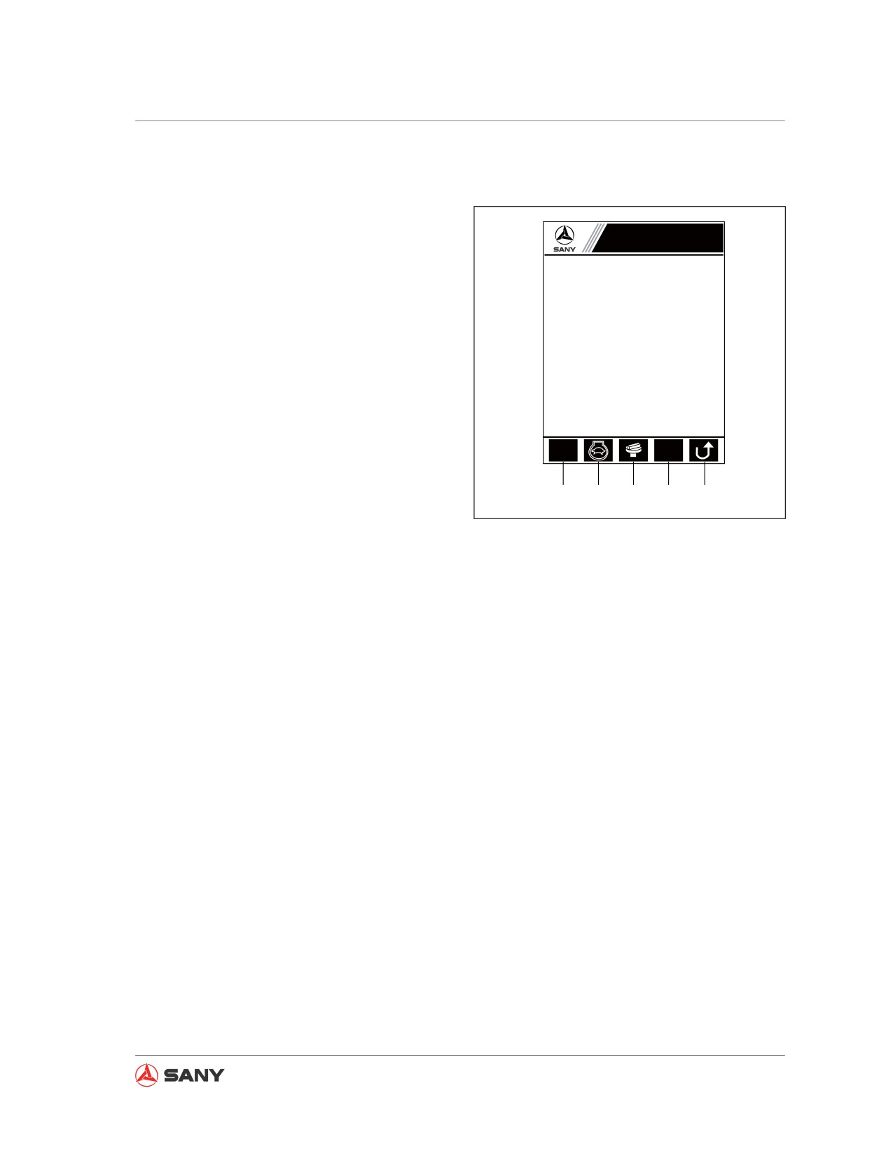
3.3.2.12 Engine Speed Calibration
Auto setup of gear positions and correspond-
ing engine speed.
Engine Speed Calibration
Screen output
Throttle gear
N:
1
1. Press [F1] to select a working mode:
Target speed
rpm: 1000
S → H → L → B → S……
Real speed
rpm: 998
2. Press [F2] to switch on/off auto decelera-
Allowable deviation
rpm:
10
tion: OFF → ON → OFF……
Real deviation
rpm:
2
3. Press [F3] to start/stop auto gear position
setup.
4. Press [F4] to start/stop auto speed setup.
L
rpm
5. Press [F5] to return to the “Main Menu”.
1
2
3
4
5
Keypad input
XP1351106017
Fig. 3-22
[F1]: Select a working mode (S, H, L or B).
[F2]: Select auto idle/full speed.
[F3]: Start/stop auto gear position setup.
[F4]: Start/stop auto speed setup.
[F5]: Return to the "Main Menu".
[ESC]: Return to the "Main Menu".
[ ↑ ]: Increase the allowable deviation by 1.
[ ↓ ]: Decrease the allowable deviation by 1.
[ ← ]: Increase the allowable deviation by 5.
[ → ]: Decrease the allowable deviation by 5.
3-23
System Functions
Remark:
●
Gear position calibration
1.
Gear position calibration can be performed without running the engine.
2.
Auto gear position calibration procedure:
1) Press [F1] to select working mode H.
2) Turn the fuel control dial to position 0. (The monitor displays 0 for gear position.)
3) Press the calibration start key [F3] to activate auto calibration mode. The blue icon for gear
position calibration will turn red.
4) Turn the fuel control dial to position 1. After 2 seconds, the monitor shows 1 for “current
gear position”. The calibration of gear position 1 is done.
5) Turn the fuel control dial to the next position. After 2 seconds the monitor shows the value
for current gear position. The calibration of this gear position is done.
6) After setting up the 11 gear positions, the red gear position calibration icon turns blue,
meaning the calibration is done successfully.
7) Press [F5] or [ESC] to exit gear position calibration.
3.
Failure to follow the above steps will fail the calibration.
●
Speed calibration
1.
Auto speed calibration requires running the engine.
2.
Auto speed calibration procedure:
1) Press [F1] to select working mode H. Press [F2] to enable full speed.
2) Turn the fuel control dial to position 1.
3) Press the speed calibration start key [F4] to enter auto speed calibration mode. The blue
icon for auto speed calibration will turn red.
4) After setting up the speed for the 11 gear positions, the red speed calibration icon turns
blue, meaning the calibration is done successfully.
5) Auto speed calibration is not applicable to gear position 0.
3-24
System Functions
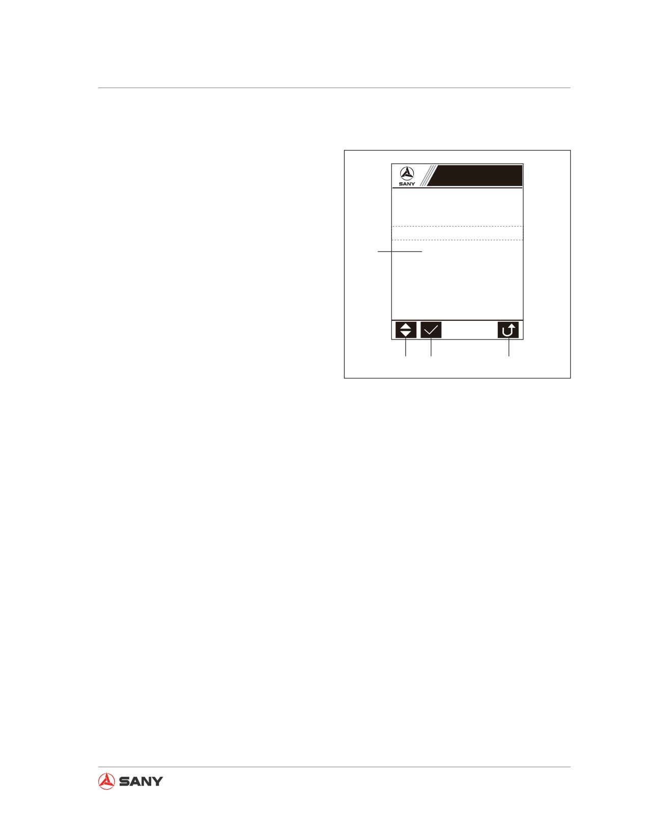
3.3.2.13 Language Selection
Selecting a system language.
Language Selection
Screen output
1. List of language options.
2. Press [F1] to scroll down the list.
中 文
3. Press [F2] to select a language.
1
4. Press [F5] to return to the “Main Menu”.
English
Keypad input
[F1]: Scroll down the list of system languages.
[F2]: Select a system language.
[F5]: Return to the "Main Menu".
2
3
4
XP1351106018
[ESC]: Return to the "Main Menu".
Fig. 3-23
[ ↑ ] [ ↓ ]: Move up or down the list.
3-25
System Functions
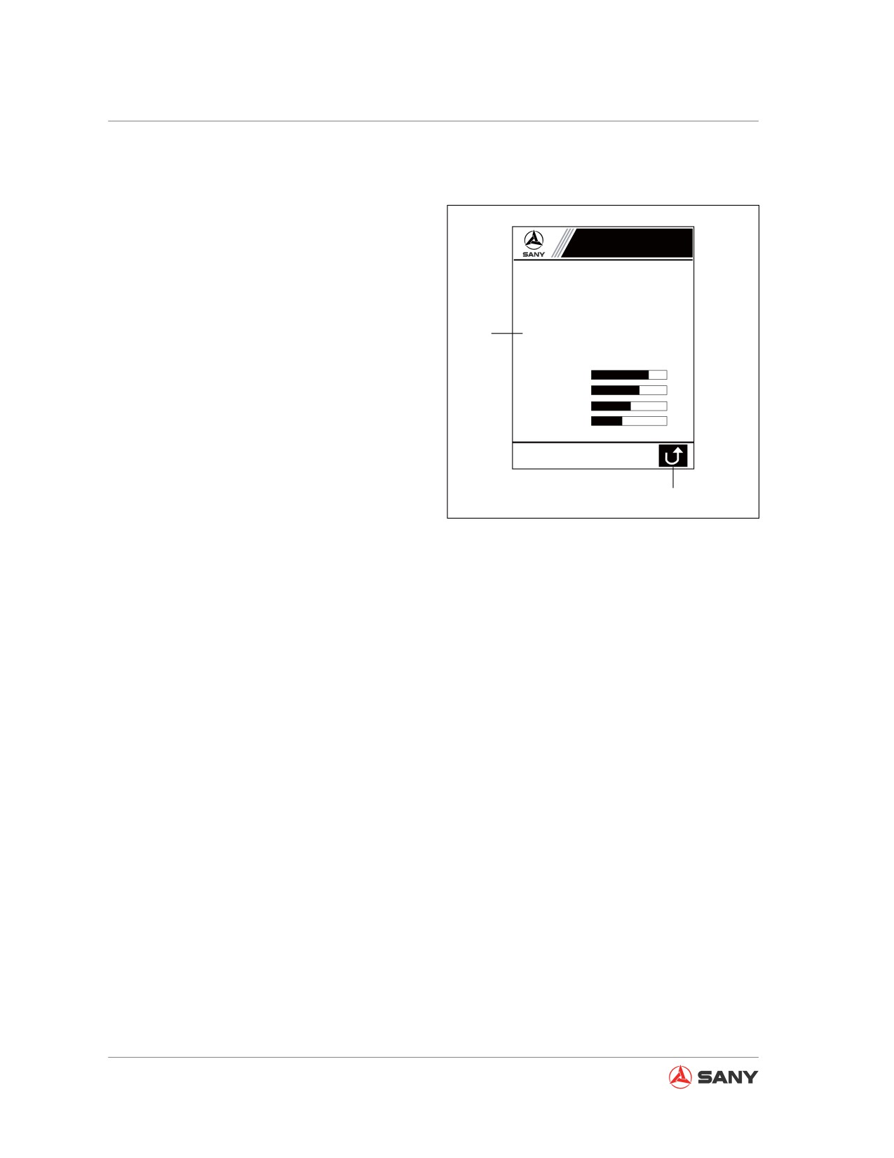
3.3.2.14 GPS Monitoring Information
Displaying GPS monitoring information.
GPS Monitoring Info
Screen output
Longitude
°
121.0W
1. Real-time display of GPS monitoring
Latitude
°
31.40N
information.
28.79P
Elevation m
Speed Km/h
4.037
2. Press [F5] to return to the “Main Menu”.
1
Number of satellites
0006
Communication signal
1023
Keypad input
S/N 1:
dB
S/N 2:
dB
S/N 3:
dB
[F5]: Return to the "Main Menu".
S/N 4:
dB
[ESC]: Return to the "Main Menu".
2
XP1351106019
Fig. 3-24
Remark:
1. In this section the letter “E” stands for East Longitude and “W” for West Longitude.
2. The letter “N” stands for North Latitude and “S” for South Latitude.
3. The letter “P” stands for the height above the seal level and “N” for the height below the
seal level.
4. The signal-to-noise ratio ranges from 0 to 99, which is indicated by a bar. The value on the
right of the bar is real S/N ratio.
5. If the elevation value is not zero and no value is displayed for the longitude and latitude, GPS
data are being received but the location has not been precisely defined yet.
6. When the communication signal is 1023, GPRS communication is regular. When it is 615, the
GPRS communication is abnormal.
7. When the communication signal changes from 7 to 0, the SIM card or the antenna has a bad
connection.
8. When the communication signal changes from 15 to 0, GPRS service is not available, the SIM
card has insufficient fund, or GPRS network is abnormal.
9. When the communication signal changes from 31 to 0, the monitoring center is closed.
3-26
System Functions
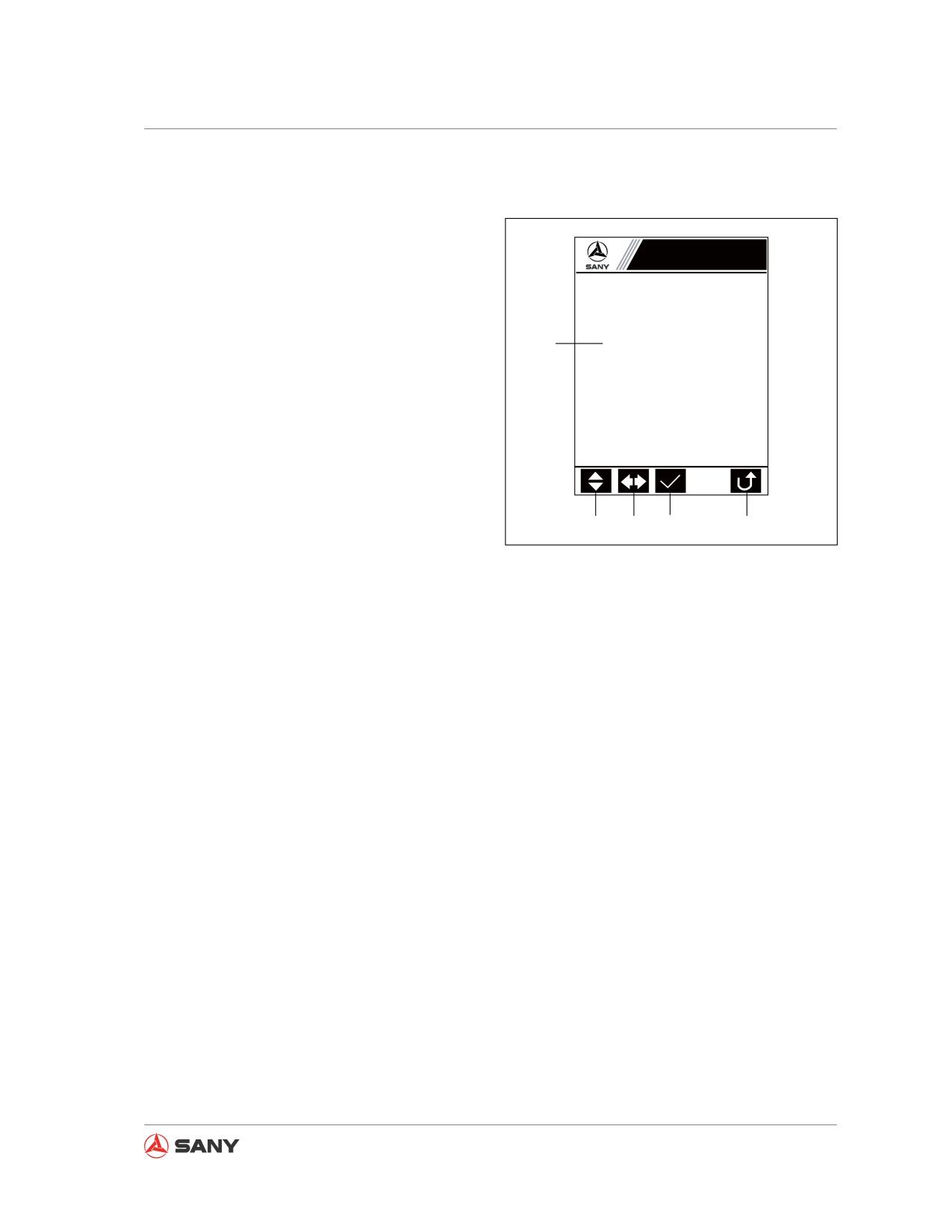
3.3.2.15 System Setup
Access to “Machine Setup” requires a pass
code.
System Setup
Screen output
Please enter the password:
1. A 5-digit pass code is required to access
“Machine Setup”, with each indicated by
1
̷Ḥ̷Ḥ̷Ḥ̷Ḥ̷
an asterisk (*) standing for a value from 0
to 9. A numeral appears at the digit where
the cursor is located while the other four
digits are in asterisk. Press [F3] to change
all digits into asterisks.
2. Press [F1 to increase/decrease the digit
value at where the cursor is located.
2
3
4
5
3. Press [F2] to move the cursor the left/right
XP1351106020
digit.
Fig. 3-25
4. Press [F3] to check the validity of pass
code. If it is correct, you are able to access
“System Setup”; if wrong, you will be
prompted by “Pass code invalid, try
again!”
5. Press [F5] to return to the “Main Page”.
Keypad input
[F1]: Increase/decrease the value at where the cursor is located.
[F2]: Move the cursor to the left/right digit.
[F3]: Check the validity of pass code. If it is correct, you are able to access the “System Set-
up”.
[F5]: Return to the "Main Menu".
[ESC]: Return to the "Main Menu".
[Enter]: Check the validity of pass code. If the pass code is valid, you are allowed to access "Ma-
chine Setup".
Remark:
The pass code is only revealed to related commissioning or service personnel.
3-27
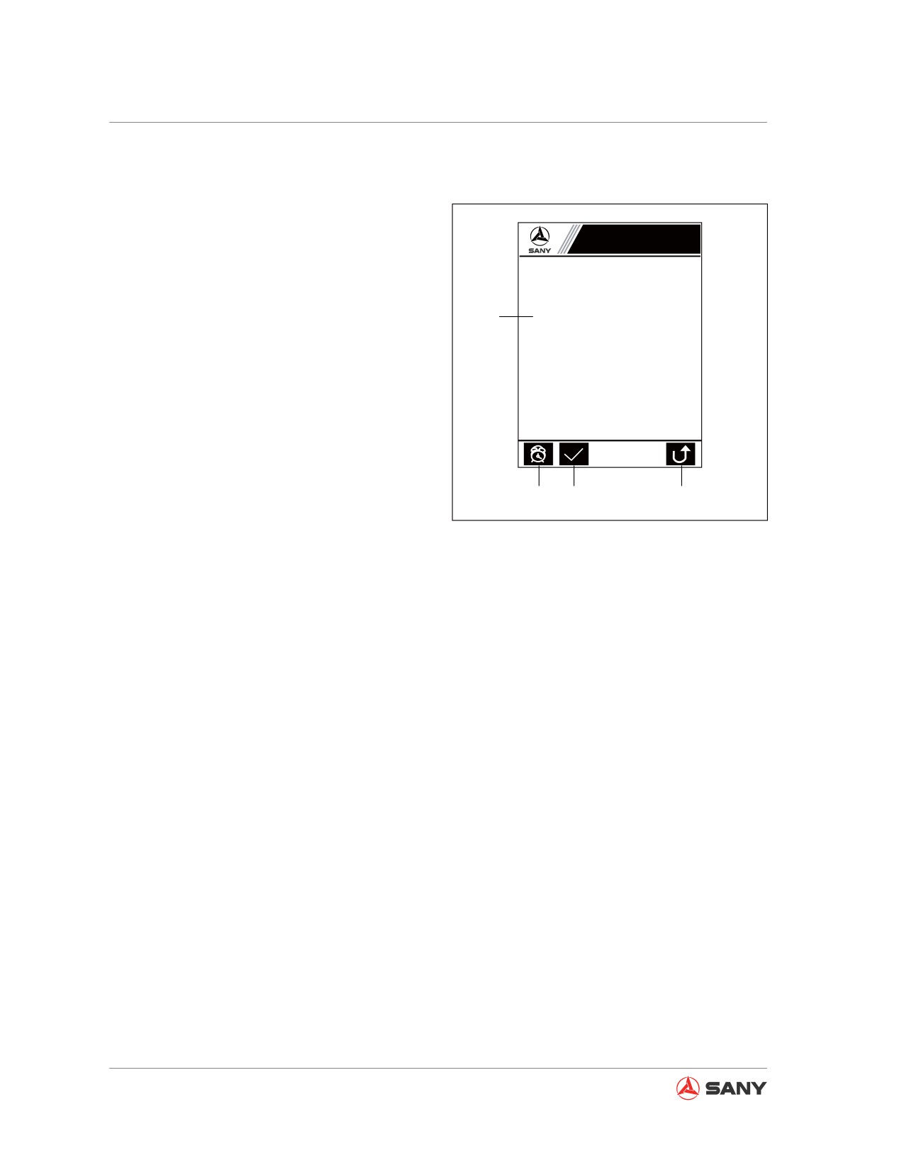
System Functions
3.3.2.16 Machine configuration setup
Setting up serial number of the machine.
Machine Config. Setup
Screen output
1. Machine serial number and operating
hours.
Machine serial No.:
018998
¥
1
Operating hours:
000012
2. Select an item to set up.
Use the arrow keys to set up.
3. Setup is OK.
ĸ Ĺ ĺ Ļ
4. Return to the “Main Menu”.
Keypad input
[
↑ ] [ ↓ ]: Increase/decrease machine serial
number by 100.
2
3
4
XP1351106021
[
← ] [ → ]: Increase/decrease machine se-
rial number by 1. Depress the key to quickly
Fig. 3-26
increase/decrease machine serial number by
10.
[F1]: Select an item to set up.
[F2]: Setup is OK.
[F5]: Return to the "Main Menu" and save the
setup.
[ESC]: Return to the "Main Menu" and save
the setup.
3-28
System Functions
3.3.2.17 Coolant Temperature
Displaying the coolant temperature.
Coolant Temperature
Screen output
1
Coolant temp ℃: 80
1. Coolant temperature.
2. Press [F5] to return to the “Main Menu”.
Keypad input
[F5]: Return to the "Main Menu".
Remark:
To access the “Coolant Temperature” page,
you need to enter the pass code on the “Sys-
2
XP1351106022
tem Setup” page.
Fig. 3-27
3-29
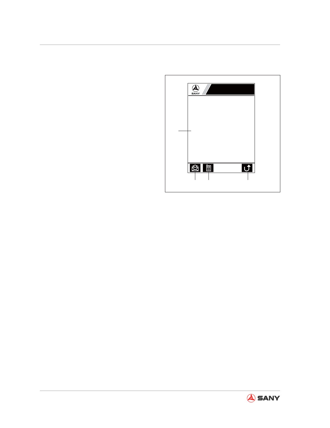
System Functions
3.3.2.18 Service Call
Sending a call to machine service center.
Call Service
Screen output
Call command: 0004
1. Call state.
1. Use the key F1 to start or finish altering
the call comand.
2. Call command.
2. Use the arrow keys (ĸ Ĺ ĺ Ļ) to alter the
call command.
3. Operator phone number.
1
Calling
Please wait!
4. Press [F5] to return to the “Main Page”.
Operator phone number: 0001 0003 0004
1. Use the key F2 to start or finish altering
the cellular phone number.
Keypad input
2. Use the arrow keys (ĸ Ĺ ĺ Ļ) to alter the
cellular phone number.
[
↑ ] [ ↓ ]: Increase/decrease the value. De-
press the key to quickly increase/decrease
machine serial number by 10.
2
3
4
XP1351106026
[ ← ] [ → ]: Move the cursor through the digits
of operator phone number.
Fig. 3-28
[F5]: Return to the "Main Page".
[ESC]: Return to the "Main Page".
[Enter]: Call the service center.
Remark:
If the call fails to be connected through, it will
be hold: “Calling
Please wait!”
A successful call will have such a feedback
that "The service center has received your
trouble information. We will contact you as
soon as possible!"
3-30
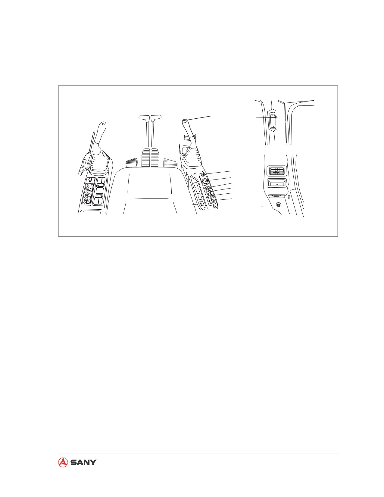
System Functions
3.4 Switches
7
8
1
2
3
4
5
6
10
9
CZ135B-1103007
Fig. 3-29
(1) Start switch
(6) Head lamp switch
(2) Fuel control dial
(7) Horn switch
(3) Work lamp switch
(8) Cab lamp switch
(4) Wiper switch
(9) Cigar lighter
(5) Washer switch
(10) Preheat switch (only for SY135C8M)
3-31
System Functions
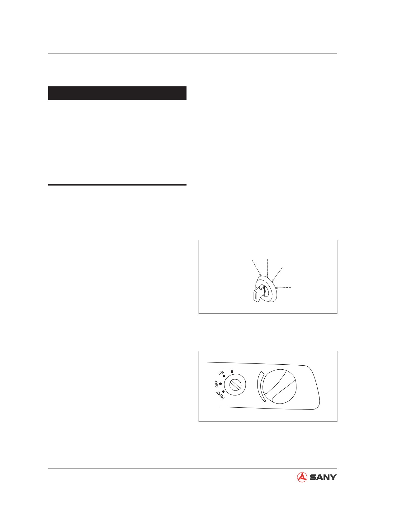
3.4.2.1 Start switch
NOTICE
If the engine does not stop at low idle
speed, the service life of engine will be
reduced. Except for emergency, never
shut off the engine while it is running at
high speed, which may otherwise cause
troubles like fatigue cracking on cylinder
cap and damage to bearing of the turbo-
charger.
Start switch is used to turn on or turn off the
engine.
(A): OFF
It allows you to insert or remove the key. All
switches of the electrical system (except out-
D
A
door lights) are off and the engine is shut
down.
B
(B): ON
C
The charging and lamp circuits are energized.
Keep the start switch in “ON” position when
CZ335-1103036
operating the engine.
Fig. 3-30
(C): START
This is engine starting position. When starting,
keep the key staying in the position. Release
START
the key immediately after the engine is started.
The key will return to ON position (B) automat-
ically.
(D): HEAT
CZ335-1103037
This is engine preheating position. Insert the
key and turn it counterclockwise to HEAT posi-
Fig. 3-31
tion. Keep the key in this position to preheat
the engine. Releasing the key, it will return to
OFF position (A) automatically and stops pre-
heating.
3-32
System Functions
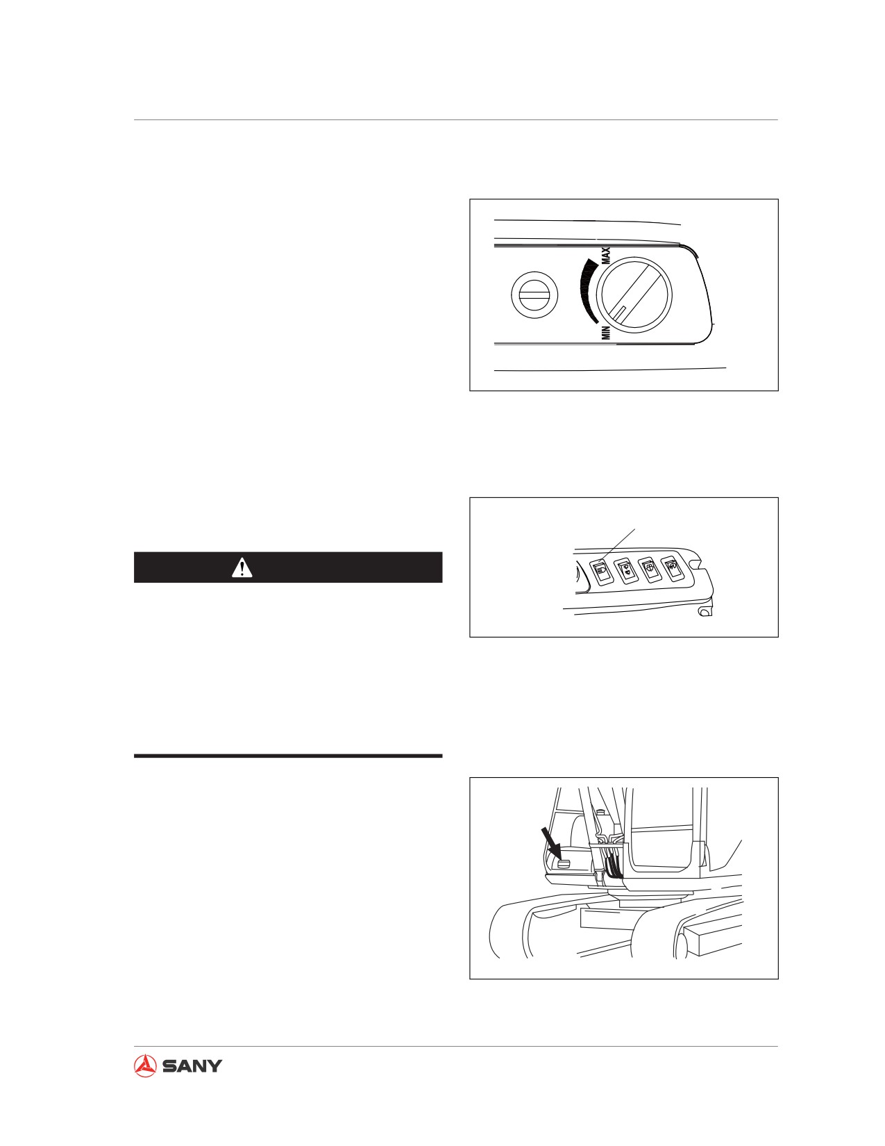
3.4.2.2 Fuel control dial
Fuel control dial is used to adjust engine
speed and output power. Turn the dial clock-
wise to increase engine speed; turn it counter-
čbĎ
clockwise to decrease engine speed.
(a) - Low Idle (MIN): Turn it counterclockwise
to MIN position.
čaĎ
(b) - Full Speed (MAX): Turn it clockwise to
MAX position.
CZ335-1103038
Fig. 3-32
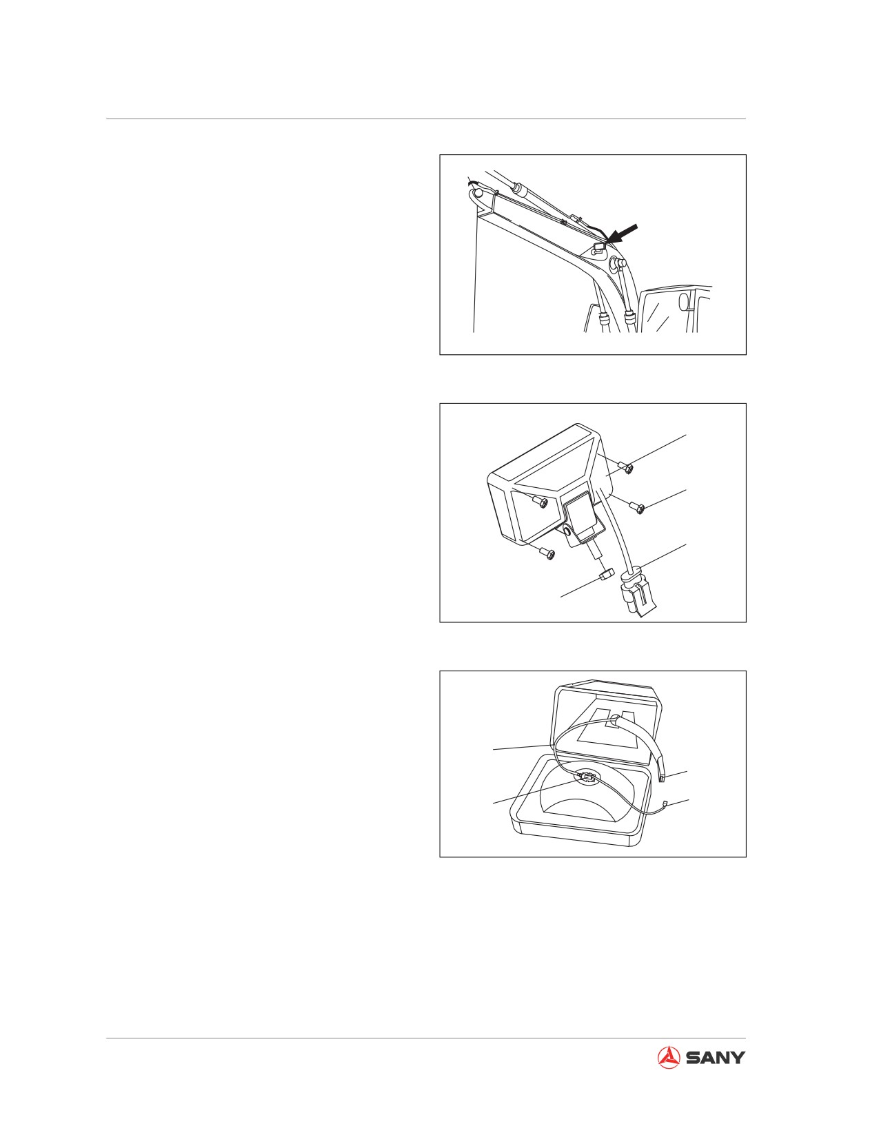
3.4.2.3 Work lamp switch
The switch is used to turn on or turn off the
Work Lamp Switch
work lamp.
WARNING
An exposed harness or loose plugging of
harness could cause short circuit between
CZ335-1103039
power supply positive wire and work lamp
Fig. 3-33
internal grounding wire during excavator
operation, which may burn the work lamp
or the entire chassis harnesses, or cause
personal injury or death.
1. Work lamp locations
a. One(1) work lamp on the chassis
CZ335-1103041
Fig. 3-34
3-33
System Functions
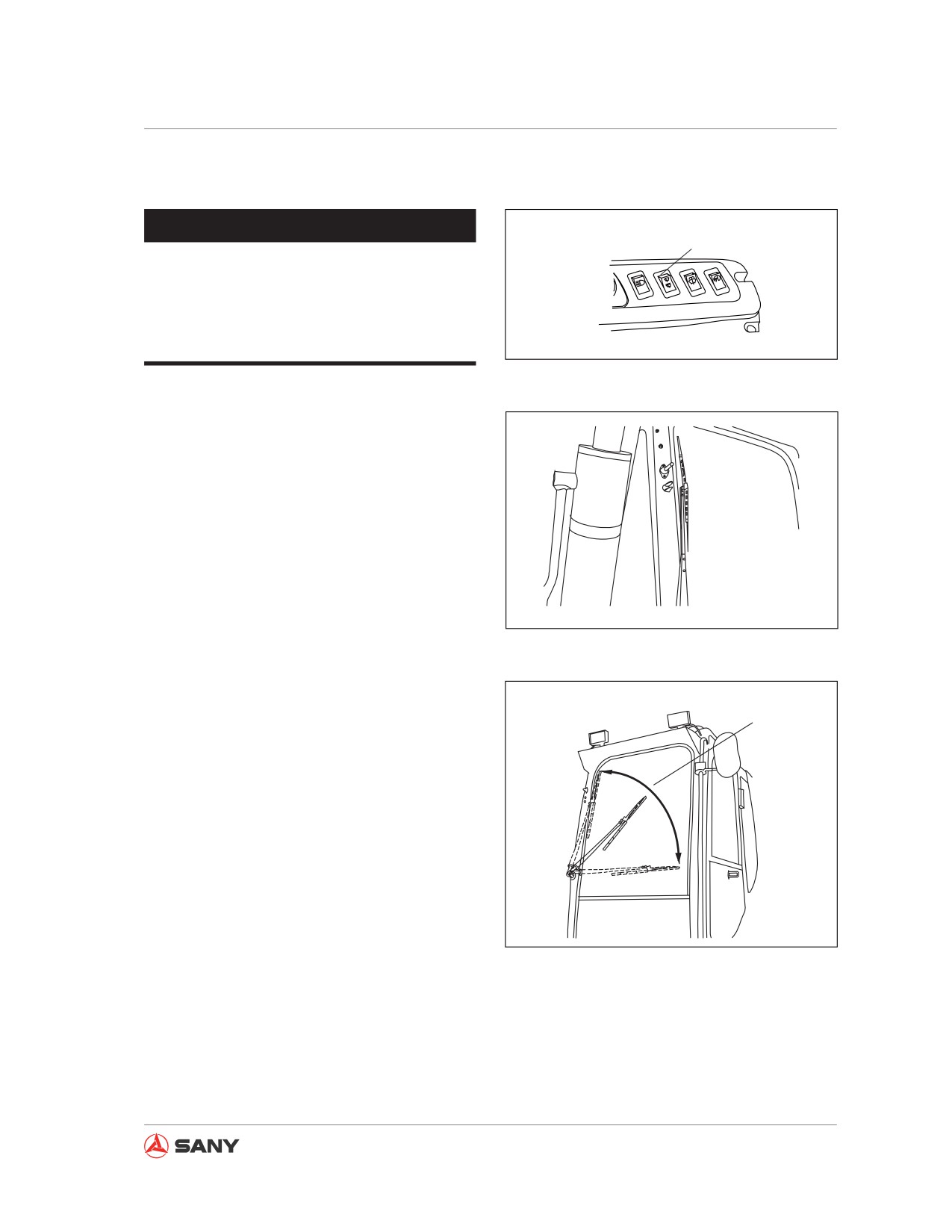
b. Two(2) work lamps on the boom
2. Work lamp external structure
(1) Work lamp seat
(2) Two-wire socket jacket
(3) Nut
(4) Work lamp screw
CZ335-1103040
3. Work lamp internal wiring
Fig. 3-35
(5) Power supply grounding wire
(6) Internal power supply positive socket
1
(7) Bulb power supply positive plug
(8) Bulb
4
2
Note:
The bulb is connected with power supply posi-
3
tive harness plug.
CZ335-1103248
Fig. 3-36
4. Replacing the bulb
1) Remove work lamp screw and open the
work lamp.
5
6
2) Remove the bulb and pull out the plug
7
(7) from the socket (6).
8
3) Install a new bulb and insert the power
CZ335-1103250
supply positive plug into the socket (6).
Fig. 3-37
4) If the harness is exposed after wiring,
use insulation tape to wrap it properly.
3-34
System Functions
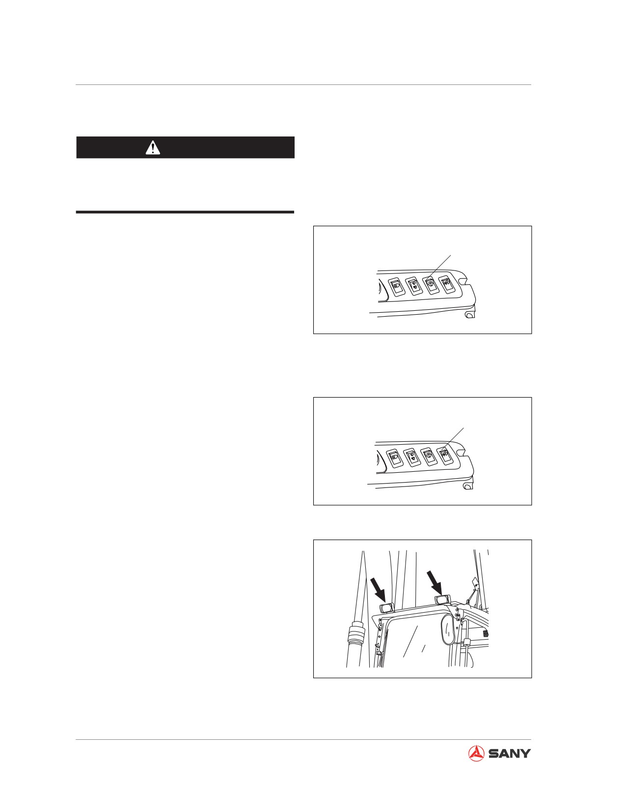
3.4.2.4 Wiper switch
NOTICE
Wiper Switch
When you use the wiper, press the washer
switch to spray some detergent in order
to prevent damaging the wiper due to fric-
tion.
CZ335-1103042
Fig. 3-38
When it is raining or the windshield is dirty,
you can press the wiper switch to activate the
windshield wiper.
CZ335-1103043
Fig. 3-39
Working range
CZ335-1103044
Fig. 3-40
3-35
System Functions
3.4.2.5 Washer switch
CAUTION
Before pressing the button, make sure that
the windshield of cab is closed.
Press washer switch to spray cleaning deter-
gent.
Washer Switch
With the switch depressed, the washer keeps
spraying detergent.
Releasing the switch, it goes back to its origi-
nal position automatically and stops spraying.
CZ335-1103045
Fig. 3-41
3.4.2.6 Head lamp switch
Head lamp switch is used to switch on or
switch off the lamps on top of the cab.
Head Lamp Switch
CZ335-1103046
Fig. 3-42
CZ335-1103047
Fig. 3-43
3-36
System Functions
3.4.2.7 Horn switch
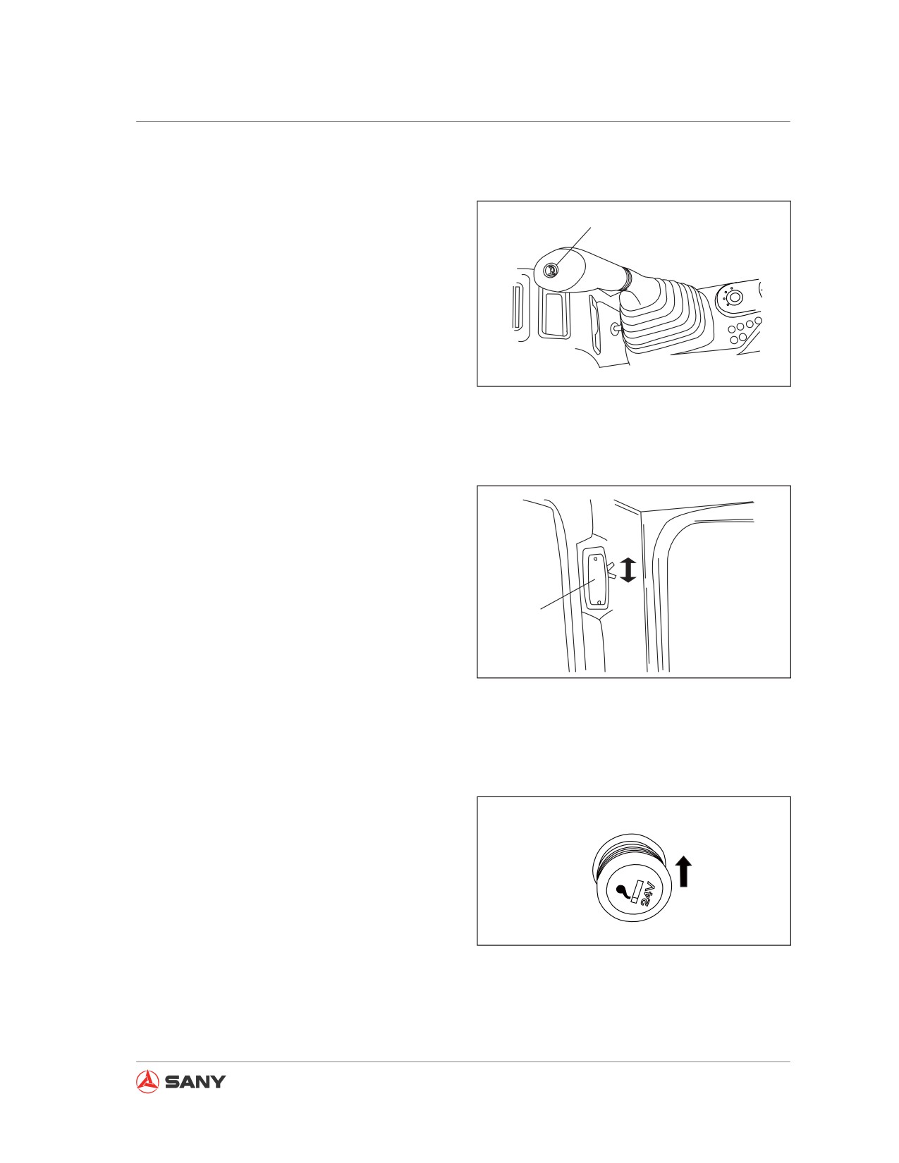
The horn switch is located on top of right joy-
Horn switch
stick. Press the switch to sound the horn.
Depress the switch to keep the horn hooting.
CZ335S-1103034
Fig. 3-44
3.4.2.8 Cab lamp
The cab lamp is mounted inside the cab. Tog-
gle the cab lamp switch to turn on/ off the cab
lamp.
čaĎ
(a) - ON
čbĎ
(b) - OFF
Cab lamp
Note:
CZ335-1103049
The cab lamp can be switched on even if the
Fig. 3-45
start switch is in the OFF position.
3.4.2.9 Cigar lighter
The cigar lighter is used to light a cigarette.
Pushing in the lighter, it returns to its original
position after a few seconds. Pull it out to light
a cigarette.
The socket of cigar lighter can be used as a
CZ335-1103050
power source for devices rated not more than
240 W (24V×10A).
Fig. 3-46
Note:
The cigar lighter is 24V.
3-37
System Functions
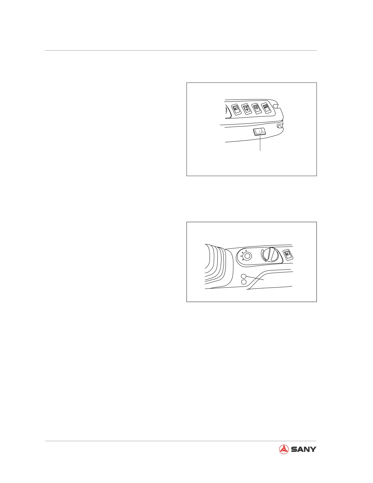
3.4.2.10 Preheat switch (only for SY135C8M)
This is engine preheat switch, which will be
used together with the preheat start switch.
● Pressing the preheat switch (6) and turning
the key counterclockwise to HEAT position,
the engine will start to preheating.
● Maintaining the key in this position, the en-
gine keeps preheating.
Preheat switch
● After releasing the key, the key will return
to OFF position (A) automatically and the
CZ135B-1103008
engine will stop preheating.
Fig. 3-47
3.4.2.11 Alternator indicator
The alternator indicator is illuminated when the
start switch is energized; the indicator goes off
while the engine is running and the alternator
is working regularly; check the generator for
any fault if the indicator is on all the time.
Alternator indicator
CZ335-1103051
Fig. 3-48
3-38
System Functions
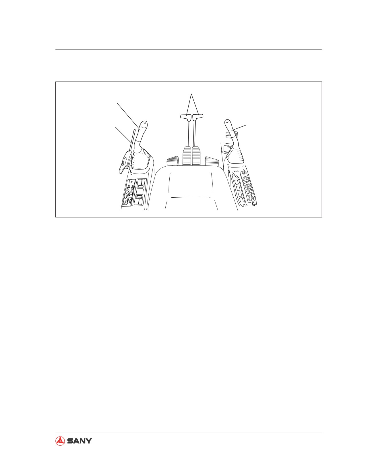
3.5 Control levers and pedals
2
3
4
1
CZ335-1103052
Fig. 3-49
(1) Hydraulic lockout control
(3) Left joystick control
(2) Travel controls
(4) Right joystick control
3-39
System Functions
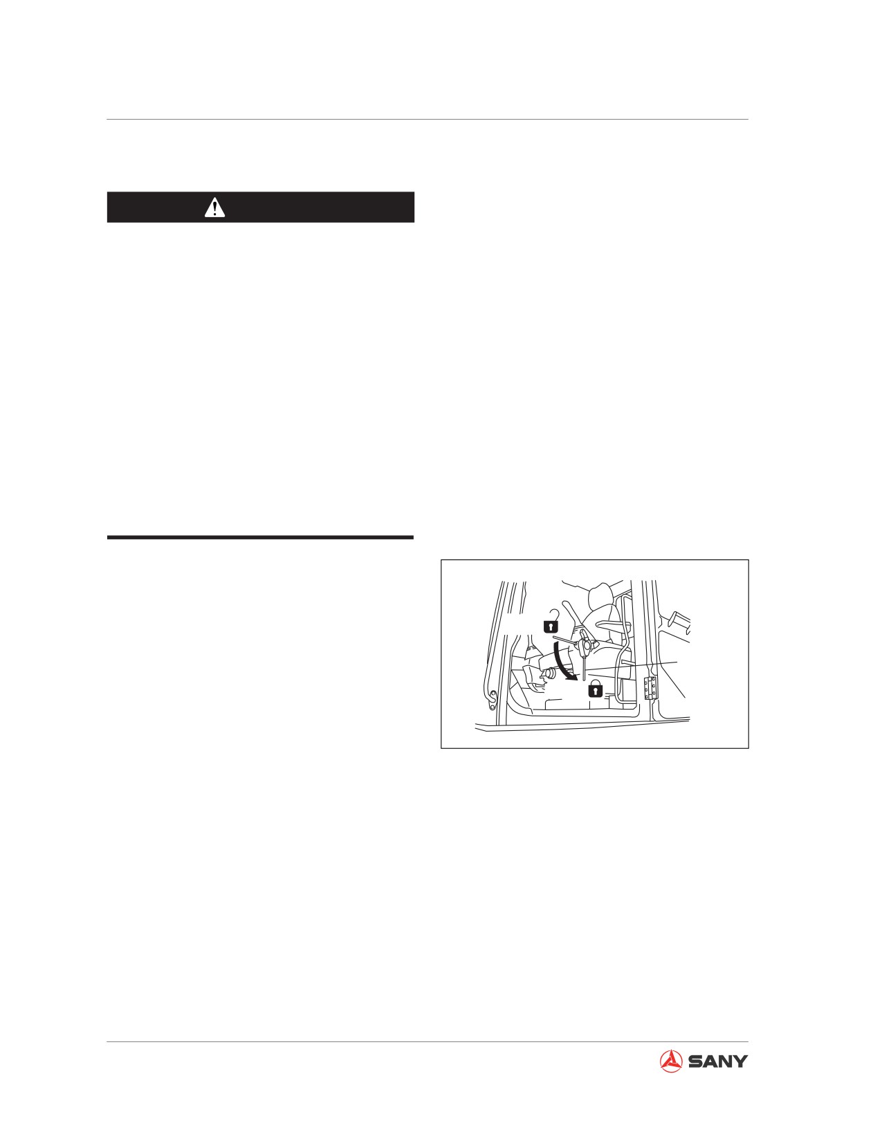
3.5.1 Hydraulic lockout control
WARNING
● Always place the hydraulic lockout
control securely in the LOCK position
before you leave the operator cab. If
the hydraulic lockout control is left un-
locked, unintended touching of it could
cause serious injury or death.
● If the hydraulic lockout control is not
in the LOCK position, move of control
lever can cause serious accidents.
Check the hydraulic lockout control as
shown in Fig. 3-50.
● Be careful not to touch the joysticks
when you engage or disengage the hy-
draulic lockout control.
Hydraulic lockout control (1) is a device used
to lock out control levers of work equipment,
swing system, travel system and attachment (if
equipped).
FREE
● LOCK position: Push down the hydraulic
1
lockout control to engage it. The machine
LOCK
will not move even if you maneuver the
controls.
CZ335-1103053
● FREE position: The machine moves ac-
cording to operation of control levers.
Fig. 3-50
This lever is a hydraulic lockout control. When
it is engaged, maneuver of control lever or
pedal would therefore lead to no movement of
the machine.
With all controls in neutral position, if any part
of the machine tends to move or moves when
you disengage the hydraulic lockout control,
it indicates a failure in your machine. In this
case, immediately engage the hydraulic lock-
out control and stop the engine. Contact your
Sany distributor to solve this problem.
3-40
System Functions
3.5.2 Travel controls
WARNING
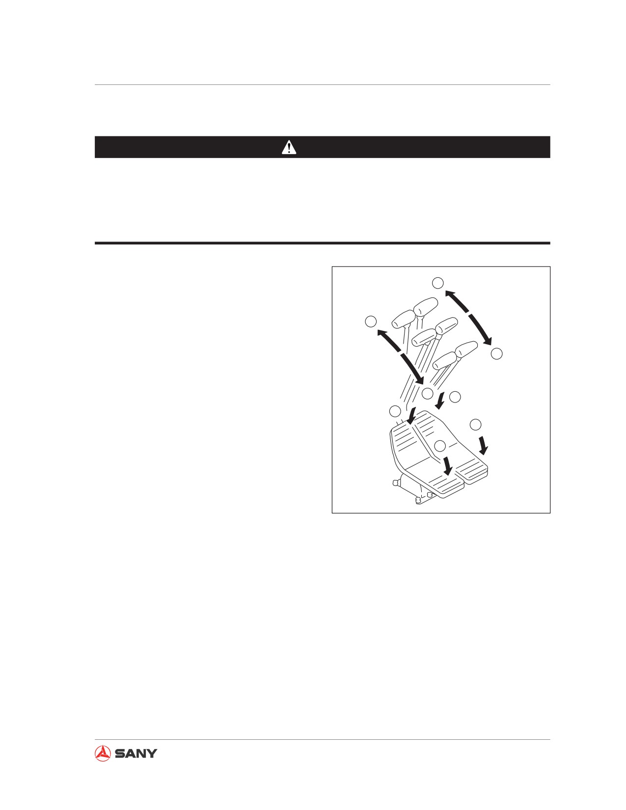
● Do not put your foot on any pedal during operation, except for travel. Unintended ped-
aling could lead to sudden move of your machine and cause severe accidents.
● Take extra care when driving or steering the machine with pedals. Do not put your foot
on any pedal when they are not used.
Control levers are used to change travel direc-
a
tion of your machine. Description in brackets
is given for pedal operation.
N
a
a - Forward travel:
Push the control lever.
b
N
(Pedal tilts forward. )
b - Backward travel:
b
a
Pull the control lever.
a
(Pedal tilts backward. )
b
N - (Neutral Position): Machine stops.
b
Remark:
When track frame faces backward direction,
CZ335-1103054
travel direction is opposite to maneuvering di-
rection of travel control lever. (Machine moves
Fig. 3-51
forward when you pull control levers and back-
ward when you push them. The left and right directions are reversed too.)
Check direction of track frame before you maneuver travel control levers. (If the sprocket is in the
rear, the track frame faces the front.)
With automatic deceleration function, travel control levers can be used to change engine speed
through the following ways.
● When travel control levers and joystick controls are in neutral position, engine speed will drop
to medium level even if fuel control dial is set above medium speed. If you maneuver any con-
trol, engine speed will rise to the level set by fuel dial control.
● If travel control levers and joystick controls are in neutral position, engine speed will decrease
by 100 rpm. About four seconds later engine will drop to the level (about 1,400 rpm) set for
automatic deceleration.
3-41
System Functions
3.5.3 Joystick controls
WARNING
● Never expose any part of your body
outside the window, which may other-
wise put you in danger of being hurt by
the boom if the joystick is moved un-
expectedly. If the window is broken or
missing, replace it immediately.
● It is important to know the positions
and functions of each joystick control.
Unexpected movement of machine
could cause personal injury.
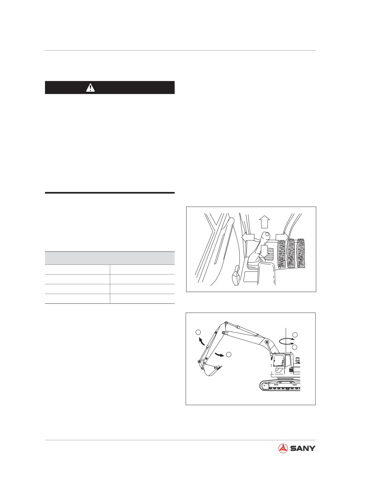
As shown in the following illustrations, oper-
ating the joysticks diagonally can realize two
①
functions in combined operation.
③
④
Left joystick control
②
Left joystick operation
① Forward
Arm OUT
② Backward
Arm IN
CZ335S-1103040
③ Left
Left swing
④ Right
Right swing
Fig. 3-52
Table 3-3
1
4
3
2
CZ335-1103056
Fig. 3-53
3-42
System Functions
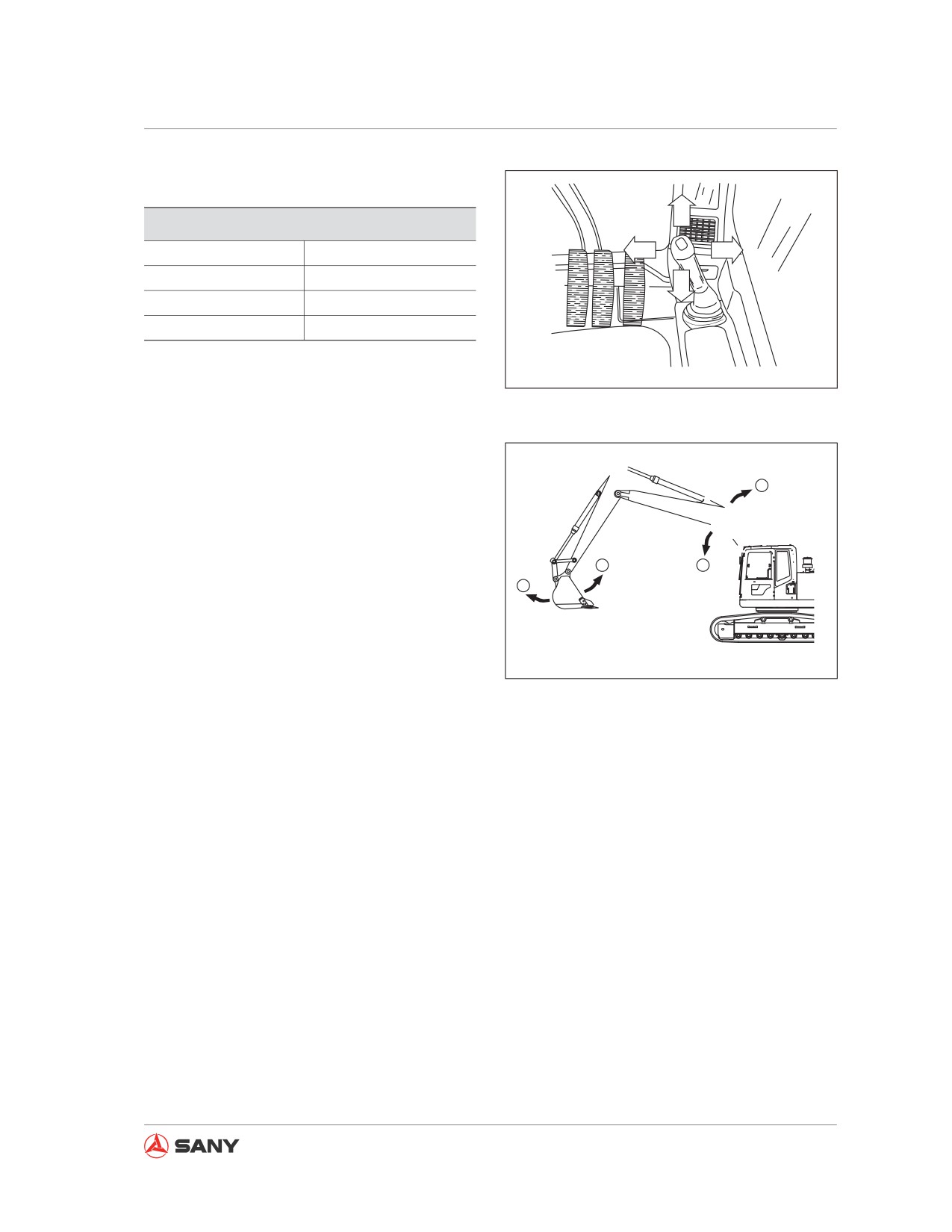
Right joystick control
⑤
Right joystick operation
⑤ Forward
Boom DOWN
⑦
⑧
⑥ Backward
Boom UP
⑥
⑦ Left
Bucket DIG
⑧ Right
Bucket DUMP
Table 3-4
CZ335S-1103042
Fig. 3-54
6
7
5
8
CZ335-1103058
Remark:
Fig. 3-55
When travel control levers and joystick con-
trols are in neutral position, engine speed will
drop to medium level even if fuel control dial
is set above medium speed. If you maneuver
any control, engine speed will rise to the level
set by fuel dial control.
If travel control levers and joystick controls are
in neutral position, engine speed will decrease
by 100 rpm. About four seconds later engine
will drop to the level (about 1,400 rpm) set for
automatic deceleration.
Releasing control lever or joystick, it goes
back to neutral position automatically and ma-
chine function stops.
3-43
System Functions
3.6 Roof Hatch
WARNING
Secure the lockout control to the LOCK
position when leaving the operator's seat.
Serious accidents can be caused if any
control lever or pedal is maneuvered by
mistake when the lockout control is in
FREE position.
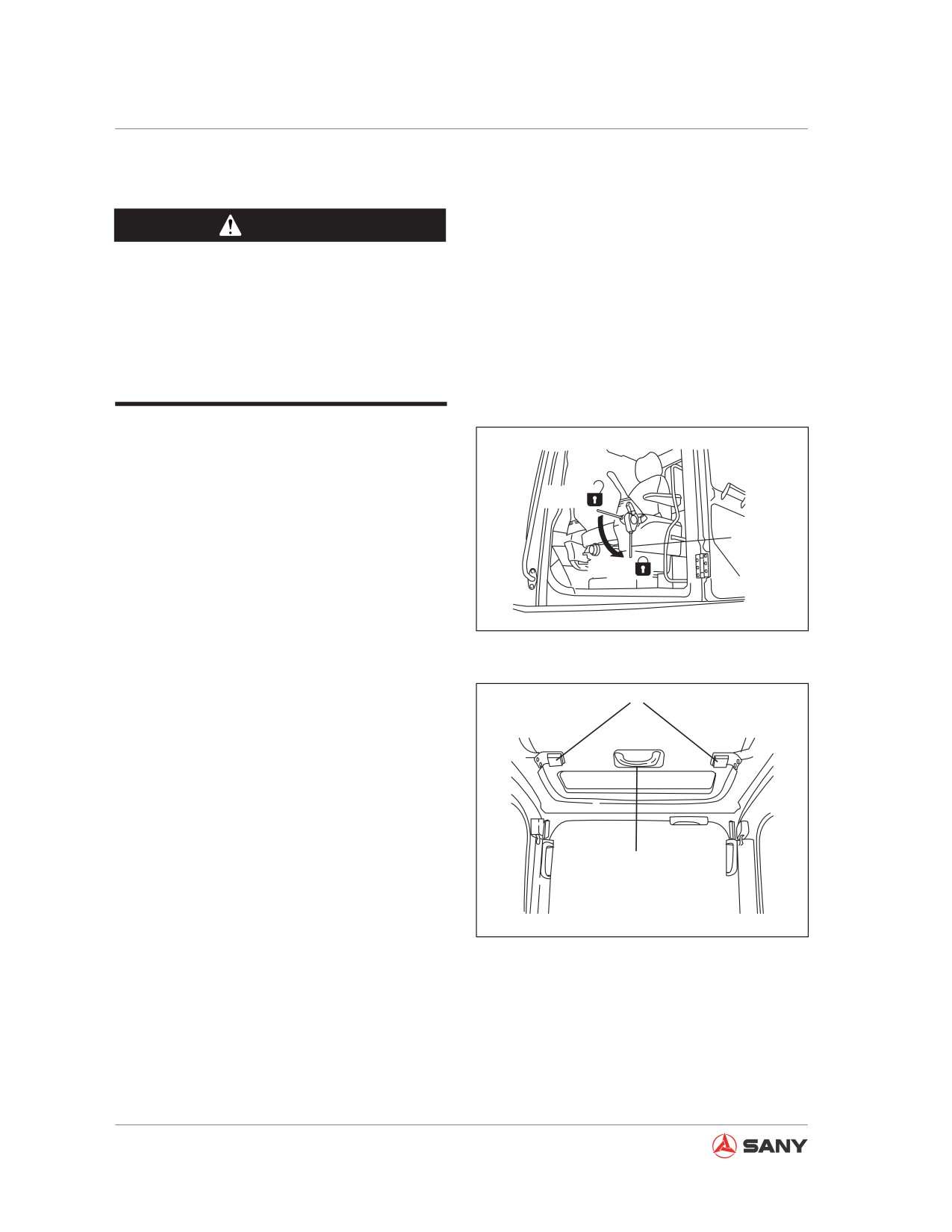
3.6.1 Opening the roof hatch
1. Place hydraulic lockout control (1) to the
LOCK position.
FREE
1
LOCK
CZ335-1103053
Fig. 3-56
2. Push upward the locks (B) at both sides of
B
grip (A). Hold the grip (A) and push upward
the roof hatch.
A
CZ335-1103060
Fig. 3-57
3.6.2 Closing the roof hatch
Hold grip (A) to pull downward the roof hatch.
The locks (B) will be engaged automatically. If
the locks are not engaged properly, open the
roof hatch and try to close it again.
3-44
System Functions
3.7 Windshield
Front window can be pulled up onto the cab
roof.
WARNING
Always leave the lockout control in the
LOCK position when opening or closing
the windshield, bottom window or cab
door. Serious accidents can be caused if
any control lever or pedal is maneuvered
by mistake when the lockout control is in
FREE position.
● Before opening or closing any window,
park your machine on a level ground, lower
the work equipment to ground, and stop
the engine.
● When opening the windshield, hold tight
the grip with both hands and pull the win-
dow upward. Never stop before the auto-
matic catch is engaged.
● When closing the windshield, the window
moves quickly under its weight. Be sure to
hold the grip tightly with both hands when
closing the window.
3.7.1 Opening the window
1. Park your machine on a level ground,
lower the work equipment to ground, and
stop the engine.
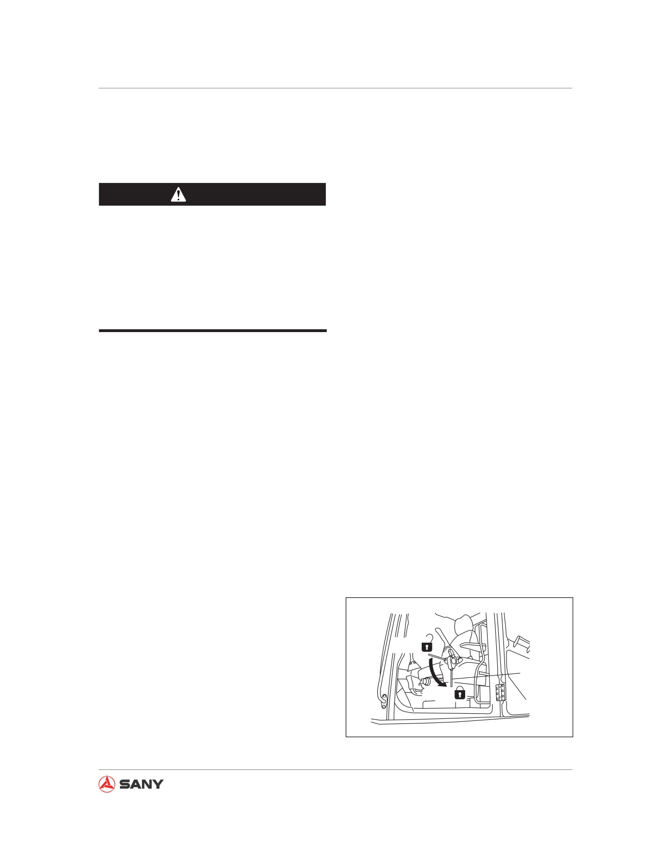
FREE
2. Place hydraulic lockout control (1) to the
LOCK position.
1
LOCK
CZ335-1103053
Fig. 3-58
3-45
System Functions
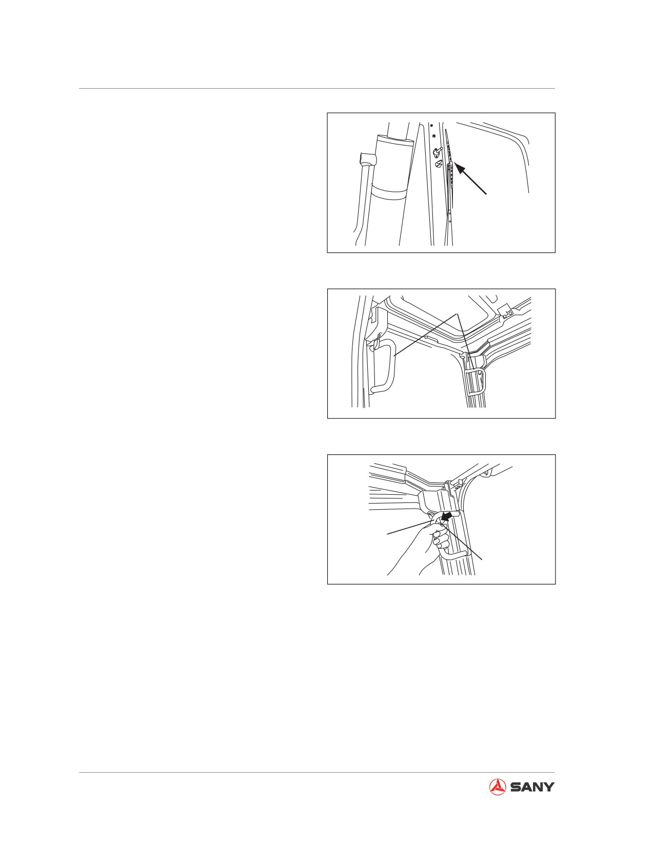
3. Check the wiper blade, which shall be
stored in the right bracket.
CZ335-1103062
Fig. 3-59
4. Hold the left and right handholds (A) of
the windshield and pull the two levers
A
(B) in order to release the locks on top
of the windshield. The windshield will be
unlocked.
CZ335-1103063
Fig. 3-60
A
B
CZ335-1103064
Fig. 3-61
3-46
System Functions
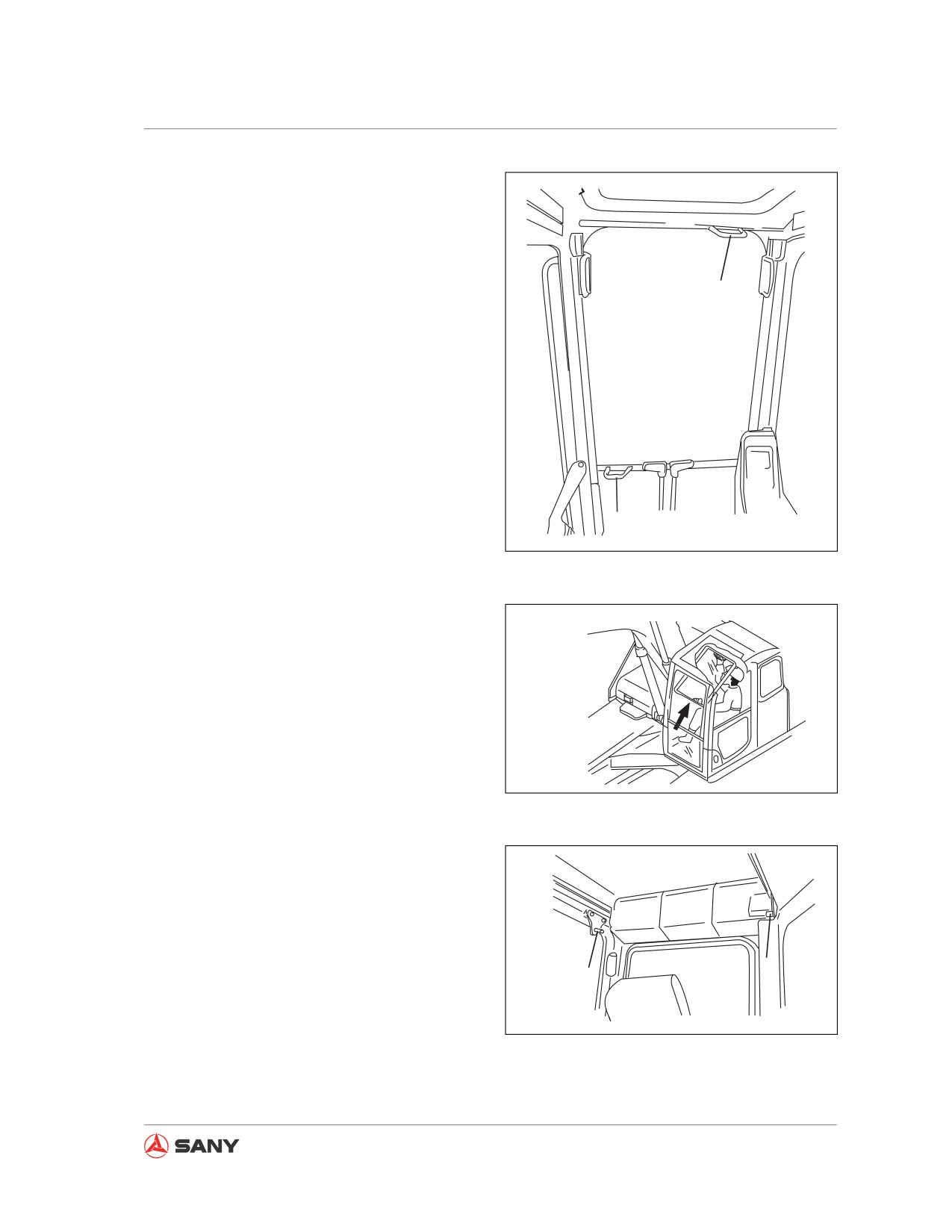
5. In the cab, hold the lower handhold (C)
with your left hand and the upper handhold
(D) with your right hand, and push the win-
dow upward. Continue to push the window
toward the latch (E)in the rear of the cab till
it is locked securely.
D
C
CZ335-1103065
Fig. 3-62
CZ335-1103066
Fig. 3-63
E
E
CZ335-1103067
Fig. 3-64
3-47
System Functions
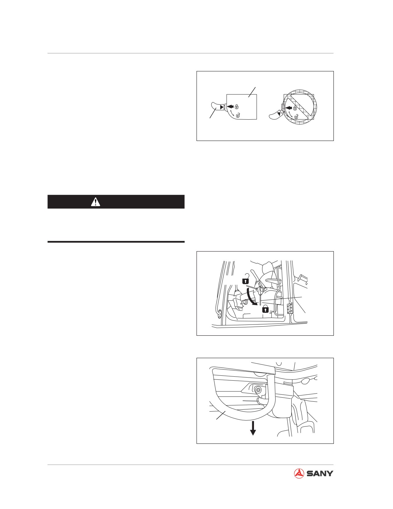
6. Check the lever (B), which shall be secured
in “locked” position.
F
● Check the arrow on the catch (F), which
should be aligned with the arrow on lever
(B). The lock is engaged.
B
● If the arrow on the catch (F) is not aligned
with the arrow on lever (B), the lock is not
CZ335-1103068
engaged. Repeat step 5 to engage the
Fig. 3-65
lock.
3.7.2 Closing the window
CAUTION
Close the windshield slowly and never get
your hand pinched by the window.
1.
Park your machine on a level ground,
lower the work equipment to ground, and
stop the engine.
FREE
2.
Secure the hydraulic lockout control (1) to
LOCK position.
1
LOCK
CZ335-1103053
Fig. 3-66
3.
Hold the left and right handholds (A) and
pull the lever (B) downward to release the
lock.
B
A
CZ335-1103069
Fig. 3-67
3-48
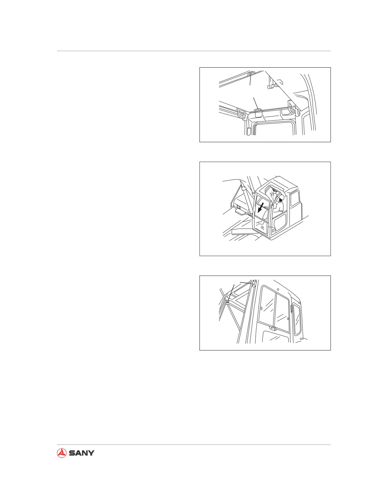
System Functions
4. Hold the lower handhold (C) with your left
hand and upper handhold (D) with your
right hand, push the window forward and
C
lower the window slowly.
D
CZ335-1103070
Fig. 3-68
CZ135B-1103009
Fig. 3-69
5. When the bottom of windshield reaches
G
the top of bottom window, push forward the
top of windshield in order to engage both
the left and right latches (G) of the locks.
CZ335-1103072
3-49
System Functions
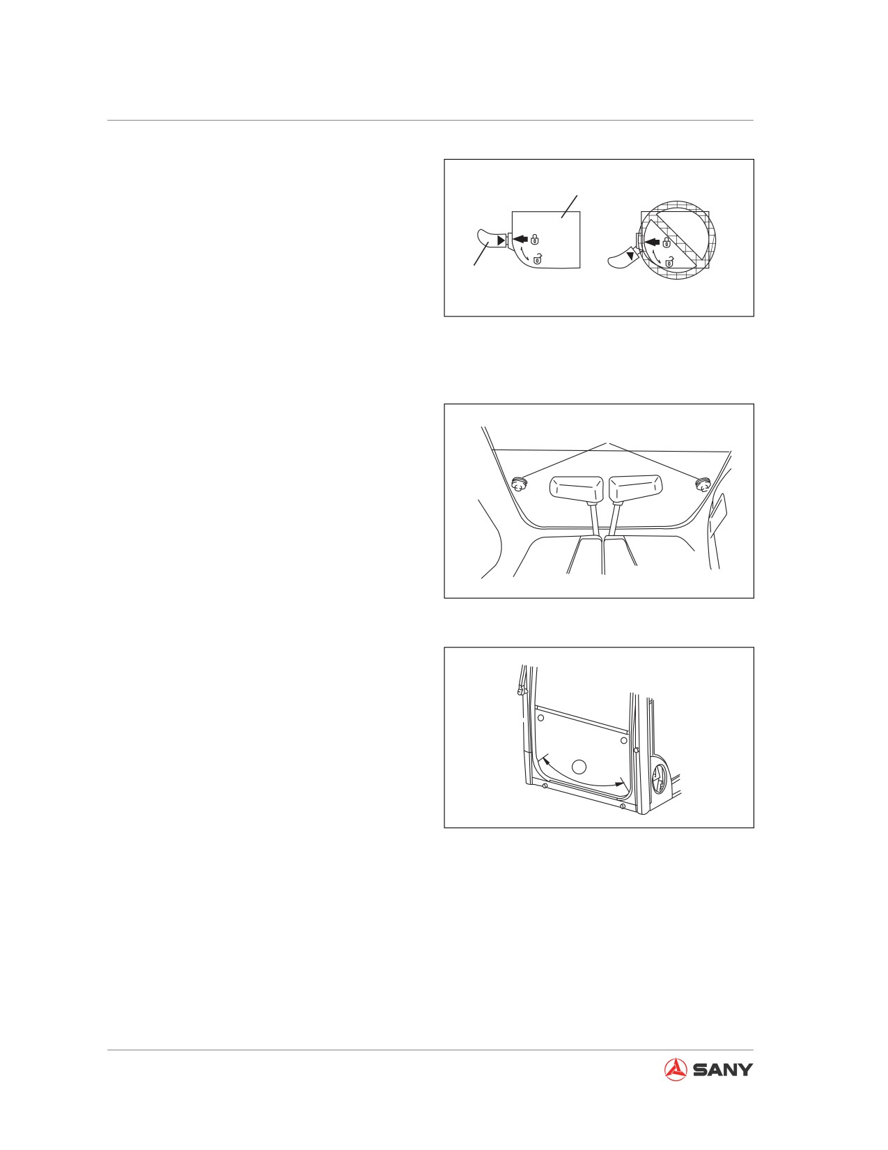
6. Check the lever (B), which should be
secured in “locked” position.
F
● Check the arrow on the catch (F), which
should be aligned with the arrow on lever
(B). The lock is engaged.
B
● If the arrow on the catch (F) is not aligned
CZ335-1103068
with the arrow on lever (B), the lock is not
engaged. Repeat step 5 to engage the
Fig. 3-70
lock.
3.7.3 Removing the lower window
1
Open the windshield, hold the grip (1) to pull
upward in order to remove the lower wind-
shield.
CZ335-1103077
Fig. 3-71
● It will be difficult to remove the windshield
in case of sand or dust building up at the
bottom of the windshield. Moreover, the
sand or dust may be brought into the cab
along with the glass when storing the win-
dow. To prevent this from happening, the
A
area (A) is to be cleaned before removing
the window.
CZ335-1103078
Fig. 3-72
3-50
System Functions
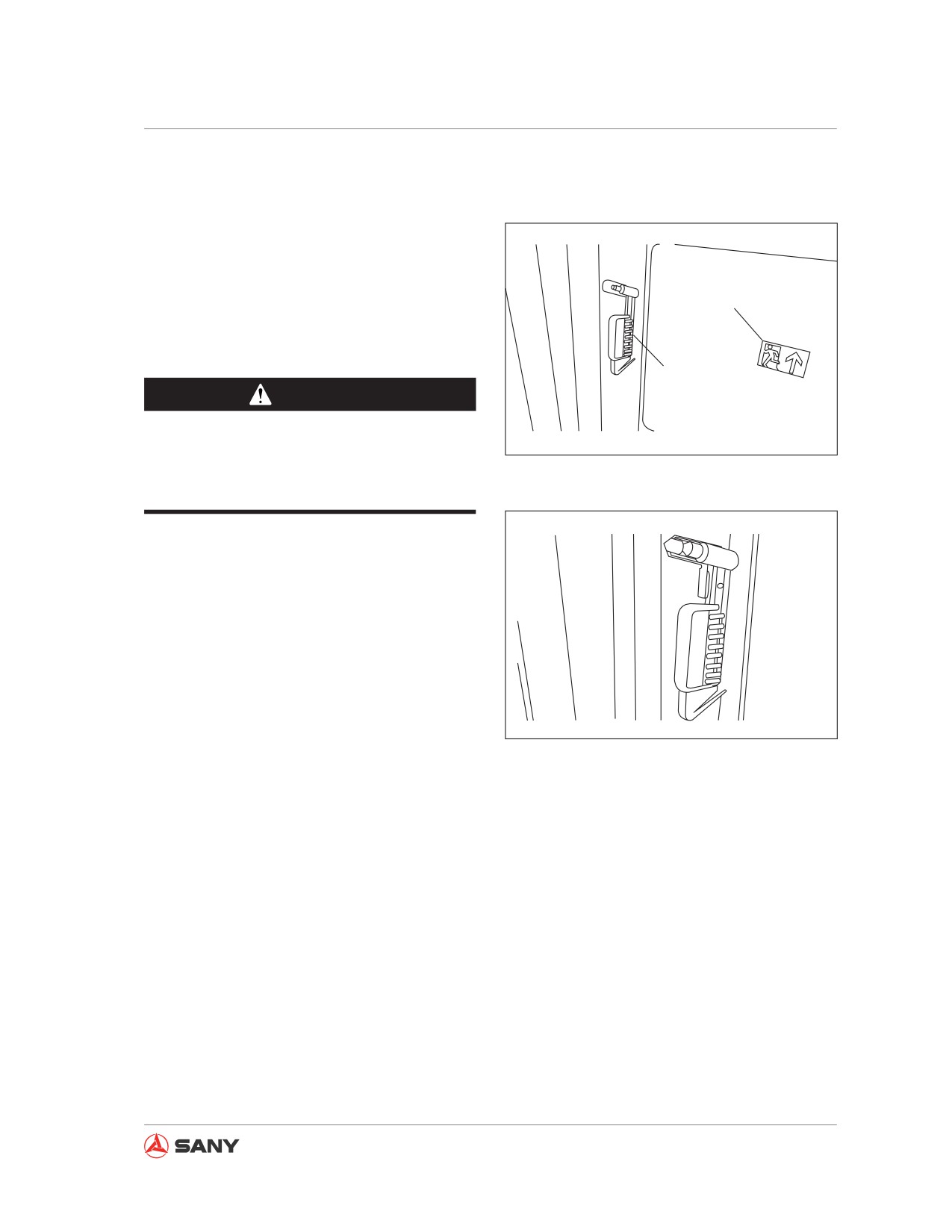
3.8 Alternate Exit
If you are unable to open the cab door in case
of emergency, use the hammer to break the
rear window and escape.
Sign of alternate exit
Never use the hammer for other purposes.
Safety hammer
CAUTION
Broken glass can cut. Be careful not to
CZ215-1103029
be hurt by broken glass when you escape
Fig. 3-73
from a broken window.
CZ215-1103030
Fig. 3-74
3-51
System Functions
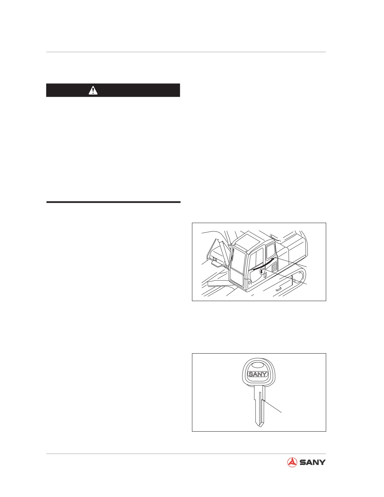
3.9 Door Catch
CAUTION
● Park your machine on a level ground
before unlocking the cab door.
● Never unlock the door on a slope. The
door may shut suddenly and cause in-
jury.
● Never expose your body or hand out
of the cab or lay your hand on the door
frame before unlocking the door. The
door may shut suddenly and cause in-
jury.
Lock the door to its position after opening it.
1. Push the cab door toward the catch (1) so
as to lock the door by engaging the catch
(1).
1
2. Before closing the door, press the joystick
(2) to the left of the operator seat to
2
release the catch (1).
CZ335-1103082
Secure the door firmly on its catch (1) after the
Fig. 3-75
door is opened.
3.10 Cover/cap with a Latch
Use the start switch key to open/close the cap
or cover.
Insert the key to its shoulder (A).
The key could be broken if turned before it is
fully inserted.
A
CZ335-1103083
Fig. 3-76
3-52
System Functions
3.10.1 Opening/closing the cover with lock
NOTICE
● Make sure to turn the cover (1) to shield
the key hole after removing the key.
Otherwise, invasion of foreign bodies
could make the switch sluggish or fail-
ing.
● A longer travel distance is required to
tighten the cover with lock. Make sure
the cover is turned in position before
you turn the key to lock the cover. If
the key is turned when the cover is not
in position, the lock plate will press
against inner wall of filler opening and
cause damage to lock cylinder.
● Be sure to have a clean O-ring seal in
lock cover. If the seal is contaminated
by iron scraps, stone pieces or other
foreign bodies, it would be damaged
during tightening and improper sealing
of lock cover could result.
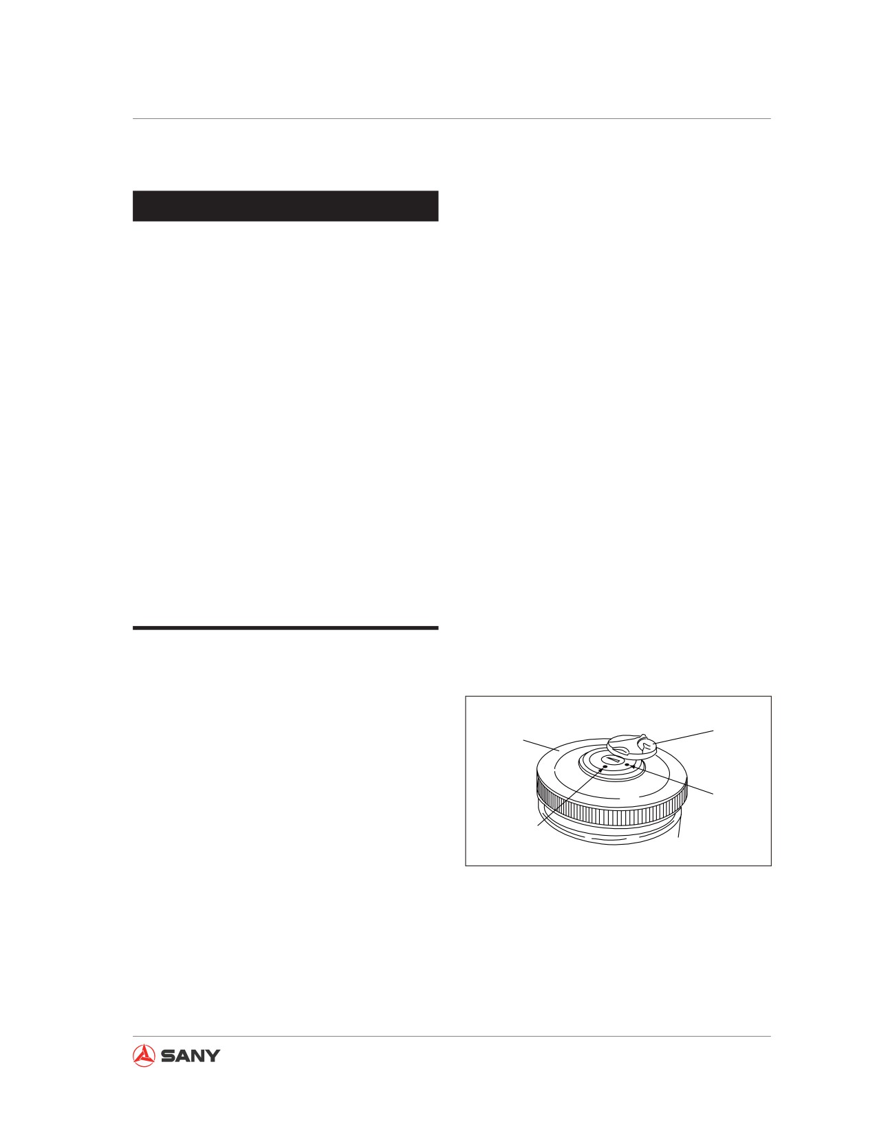
Opening the cover
1. Turn to open the key hole cover(1).
1
2. Insert the key into the key hole.
2
3. Turn clockwise the key to align the key
notch to the mark (A) on the cover. Open
B
the cover(2).
A
Position (A): unlocked
CZ215-1103001
Position (B): Locked
Fig. 3-77
3-53
System Functions
Closing the cover
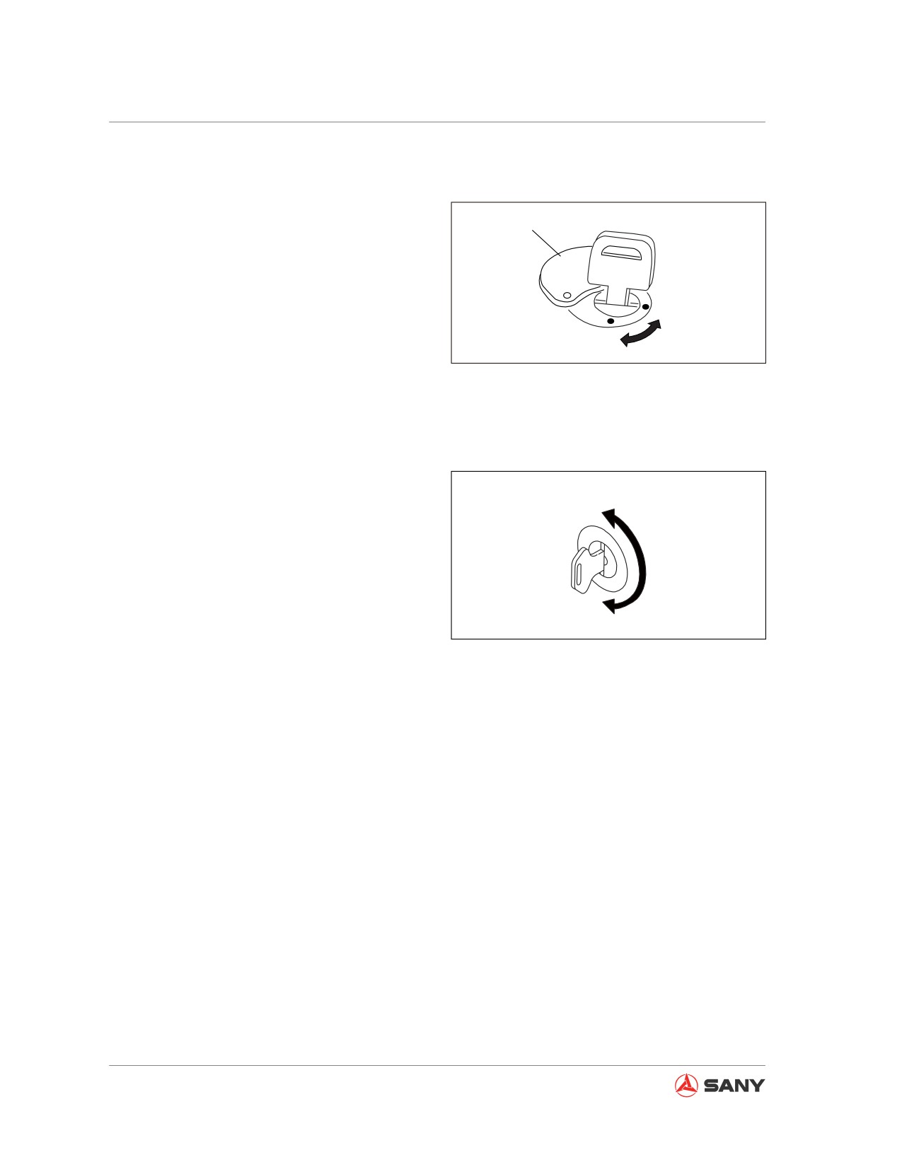
1. Screw on the cover(2) and insert the key
into the key hole.
1
2. Turn the start switch key to “locked” posi-
tion (B), and remove the key.
B
3. Turn the cover (1) to shield key hole.
A
CZ215-1103002
Fig. 3-78
3.10.2 Opening/closing the cap with
lock
A
Opening the cap
1. Insert the key.
2. Turn the key counterclockwise and open
the cap with its lever.
B
CZ335-1103085
Position (A): unlocked
Fig. 3-79
Position (B): locked
Closing the cap
1. Close the cap properly and insert the key.
2. Turn the key clockwise and remove the
key.
3-54
System Functions
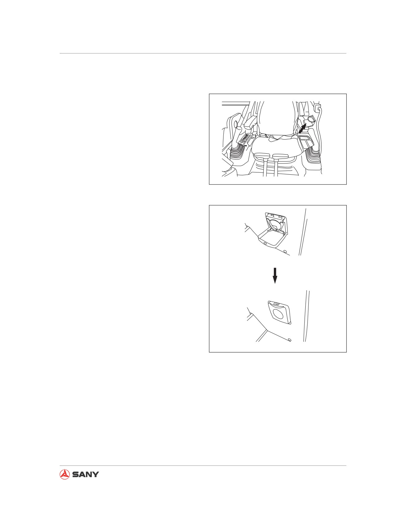
3.11 Cup Holder
A cup holder has been designed and installed
to the left side of operator in order to hold bev-
erage.
CZ335-1103086
Fig. 3-80
● As shown in the illustration, the cup holder
can be folded to prevent damage when it is
not used.
CZ335-1103087
Fig. 3-81
3-55
System Functions
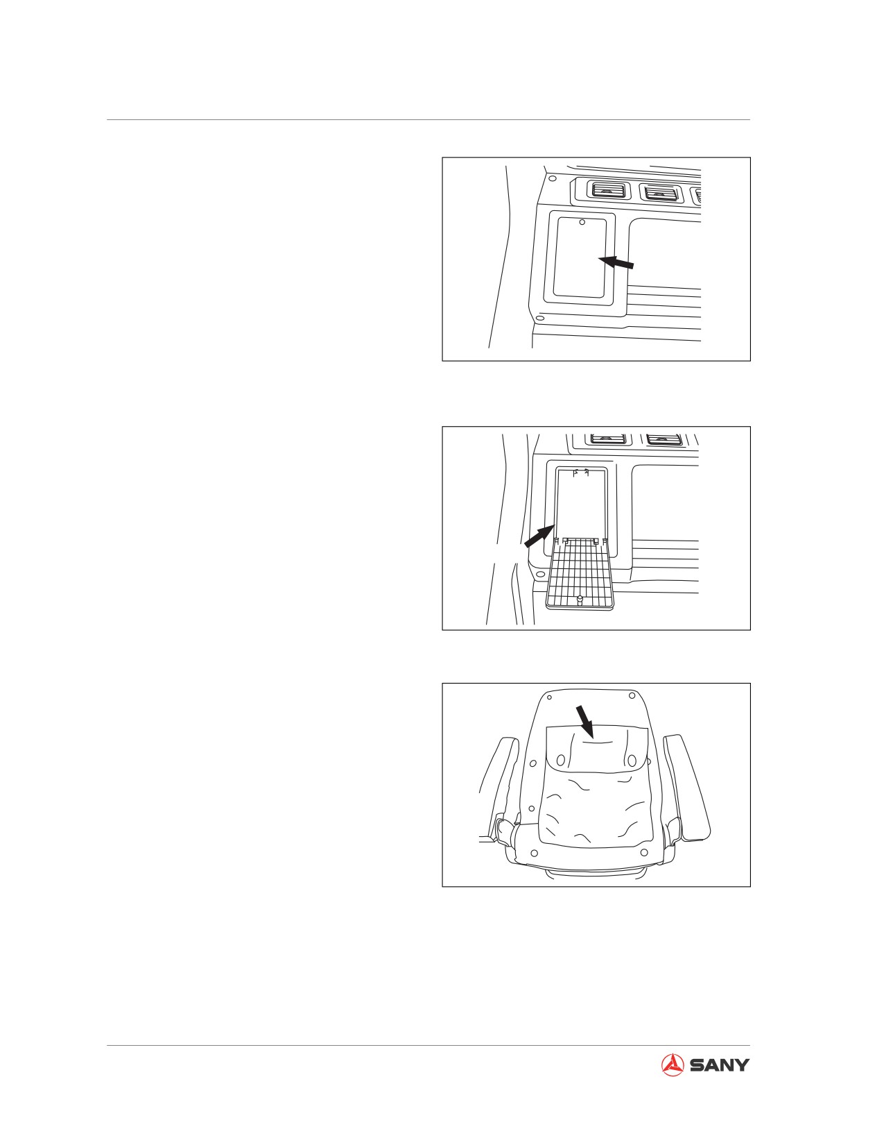
3.12 Storage Box
● Located to the rear right of operator seat,
the storage box is used to keep your drinks
warm in winter and cool in summer.
Closed
● Cool or warm air is sent into the storage
box according to the setting of air-condi-
tioner.
CZ335-1103088
Fig. 3-82
Open
CZ335-1103089
Fig. 3-83
3.13 Literature Bag
● The bag is located on the back of the op-
erator seat.
● The "safety, operation and maintenance
manuals" can be stored in this bag for you
to refer to at any time.
Fig. 3-84
3-56
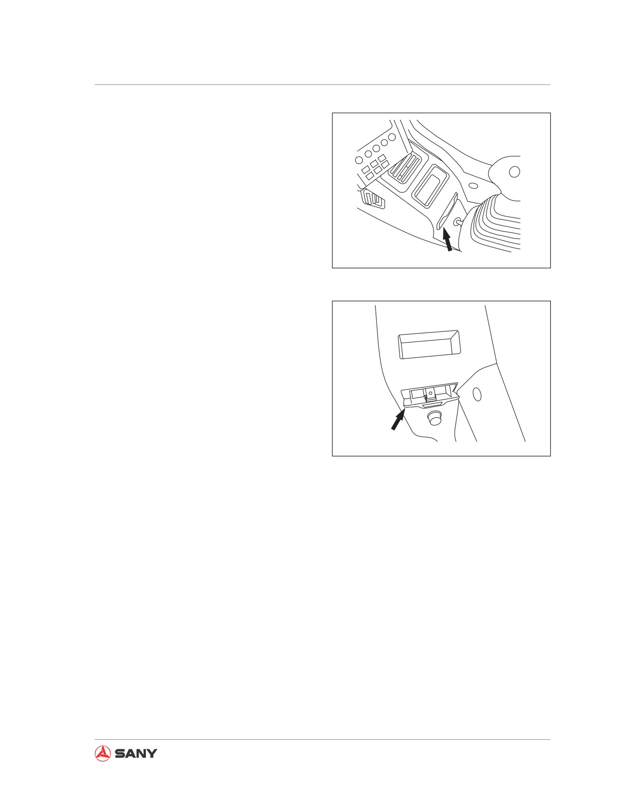
System Functions
3.14 Ashtray
● The ashtray is above the cigar lighter.
● Make sure that the cigarette is extin-
guished before closing the ash tray.
Closed
CZ335-1103091
Fig. 3-85
Open
CZ335-1103092
Fig. 3-86
3-57
System Functions
3.15 Air Conditioning System
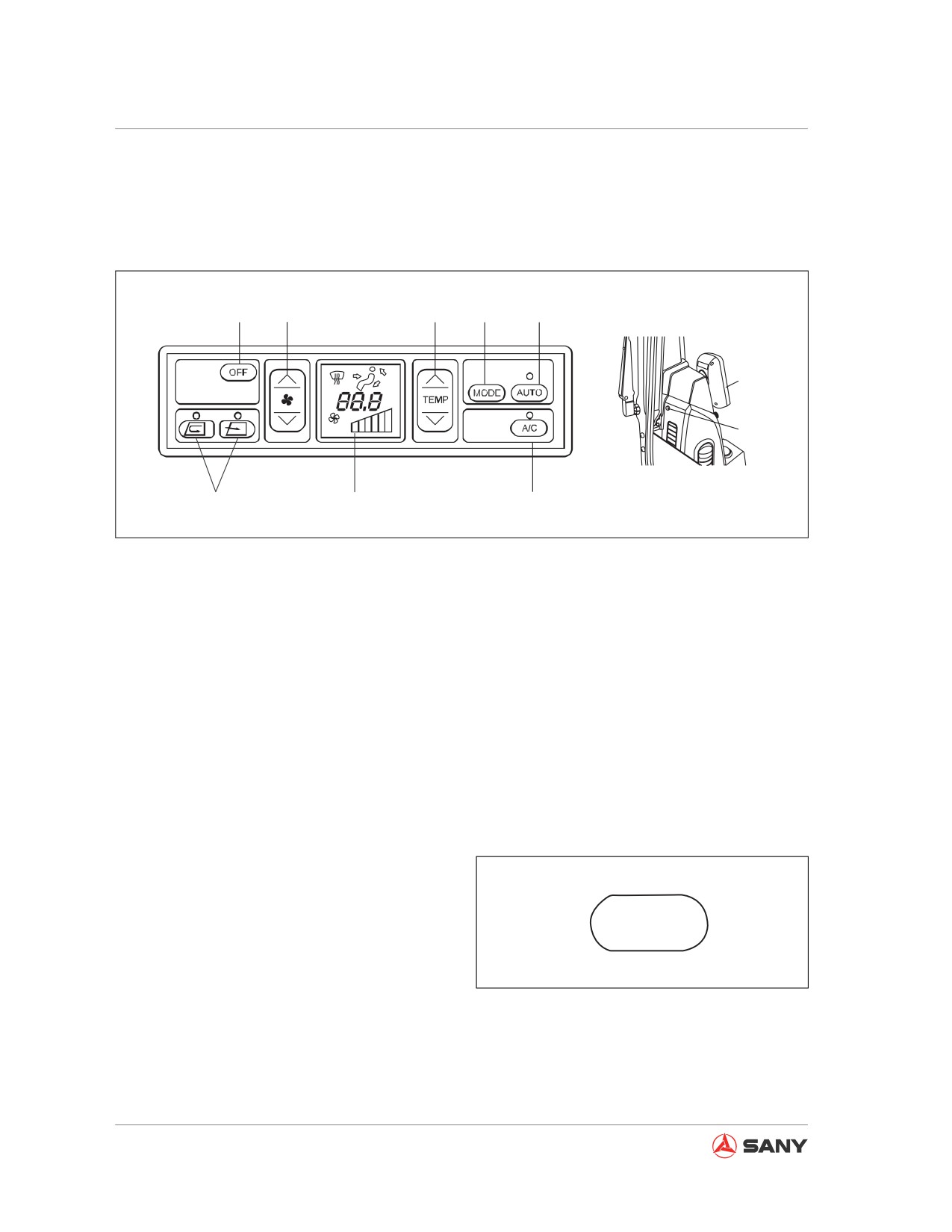
3.15.1 Control panel
1
2
3
4
5
Monitor
FULL AUTO AIRCONDITIONER
9
6
7
8
CZ215-1103037
Fig. 3-87
Remark:
(1) Power-off switch
(2) Fan switch
After the automatic control switch (5), fresh
(3) Temperature switch
air/recirculation switch (6) and air conditioner
(4) Air outlet selector switch
switch (8) are switched on, the indicator above
(5) Automatic control switch
the corresponding switch will be illuminated.
(6) Fresh air/Recirculation switch
(7) LCD panel
(8) Air conditioner switch
(9) Sunlight sensor
(1) Power-off switch
This switch (1) is used to stop the fan and air-
conditioner.
When the power-off switch (1) is pressed,
OFF
the temperature and air flow displayed on the
LCD panel disappear, the indicators above the
CZ335-1103094
automatic control switch and air conditioner
switch go out, and the operation stops.
Fig. 3-88
3-58