SANY Crawler Hydraulic Excavator SY115C9, SY135C8, SY135C9, SY155H. Safety, Operation and Manitenance Manual - page 3
Safety
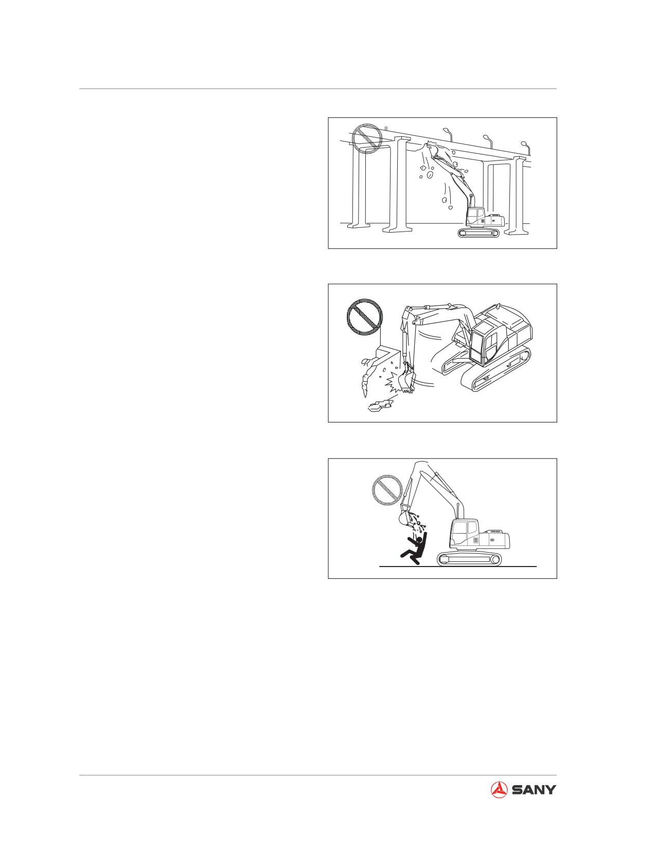
● Never tear down any structure over your
machine. The falling of broken objects or
collapse of building could damage your
machine and cause personal injury or
death.
CZ335-1102051
Fig. 2-70
●
Never break anything with the impact force
of work equipment as broken pieces could
lead to personal injury, the work equipment
could be damaged, and the counter-action
of impact force could roll over your ma-
chine.
●
Generally speaking, it is easier to tip over
with the work equipment at one side than it
is positioned in the front or rear.
CZ335-1102052
Fig. 2-71
●
Lifting, moving or swinging the bucket shall
never pass over anybody or a truck's cab.
The falling of substances from the bucket
or collision of buckets could result in per-
sonal injury or machine damage.
●
The use of crusher or other heavy working
unit could cause your machine to lose bal-
ance and tip over. When operating on a flat
CZ335-1102053
surface or slope:
Fig. 2-72
Never lower, swing or stop the working unit
suddenly.
Never extend or retract the boom cylinder
suddenly as which may cause your ma-
chine to tip over due to impact.
2-50
Safety
2.4.3 Parking the machine
2.4.3.1 Select a parking place
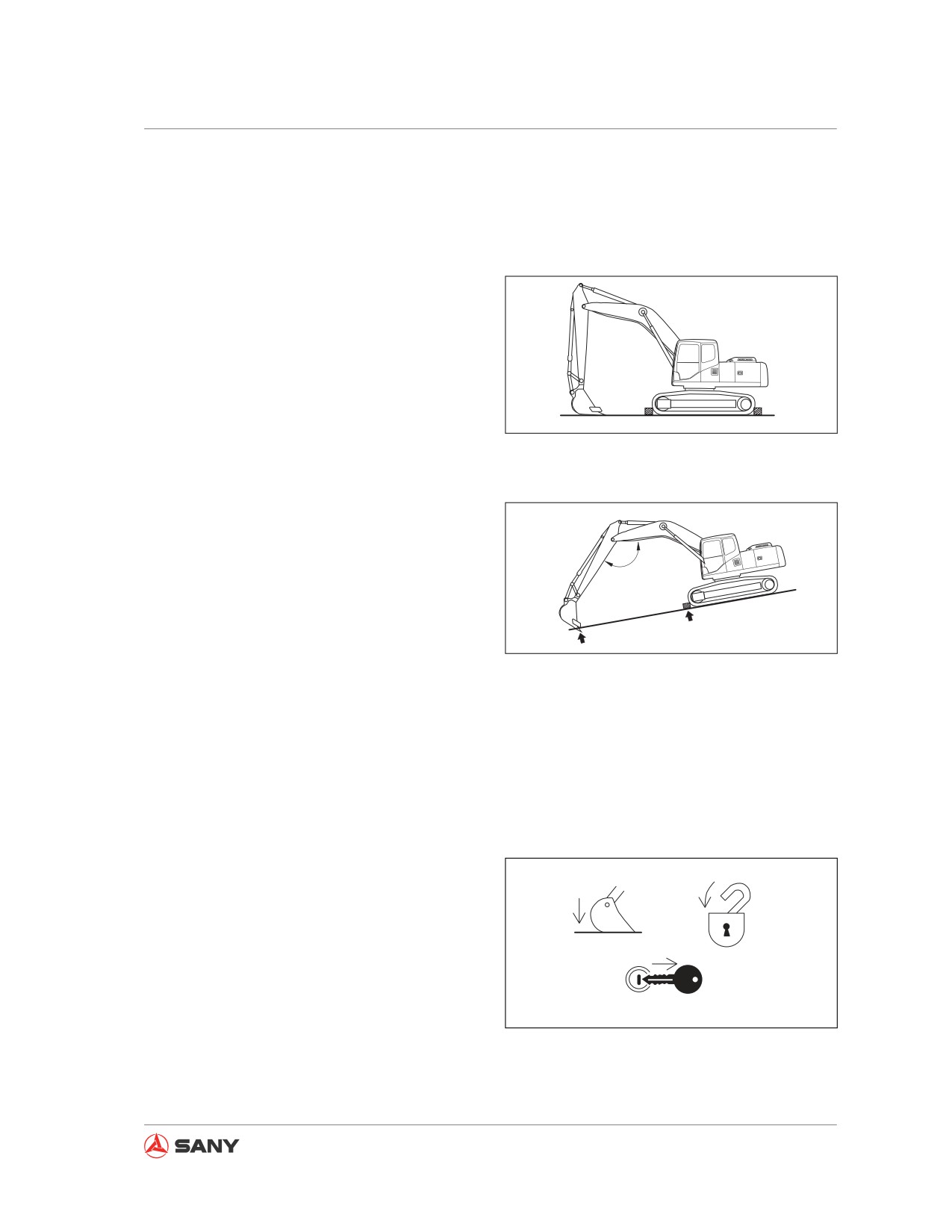
● Park your machine on a solid and flat sur-
face.
● Park the machine in an ares free of such
hazards as falling stones or landslide. If the
terrain is low, park it in a relatively higher
place.
● If you have to park the machine on a slope,
CZ335-1102054
observe the following instructions:
Fig.
2-73
● Position the bucket in the downhill di-
rection and cut the bucket tips into the
earth.
● Chock the tracks to prevent unexpected
movement.
120°
● Never park your machine on a road under-
going construction. If you have to park your
machine in such a place, flags are to be
CZ335-1102055
used on daytime and signal lamps at night
to warn other people or vehicles according
Fig.
2-74
to local regulations.
2.4.3.2 Machine shutdown
Follow the procedures below to shut down the
machine.
1. Stop the machine.
2. Position the machine properly.
3. Lower work equipment to ground or hold it
in a position.
4. Reduce engine speed to idle and keep it
running for 5 minutes.
CZ335-1102056
Fig.
2-75
5. Turn start switch to OFF position to stop
the engine.
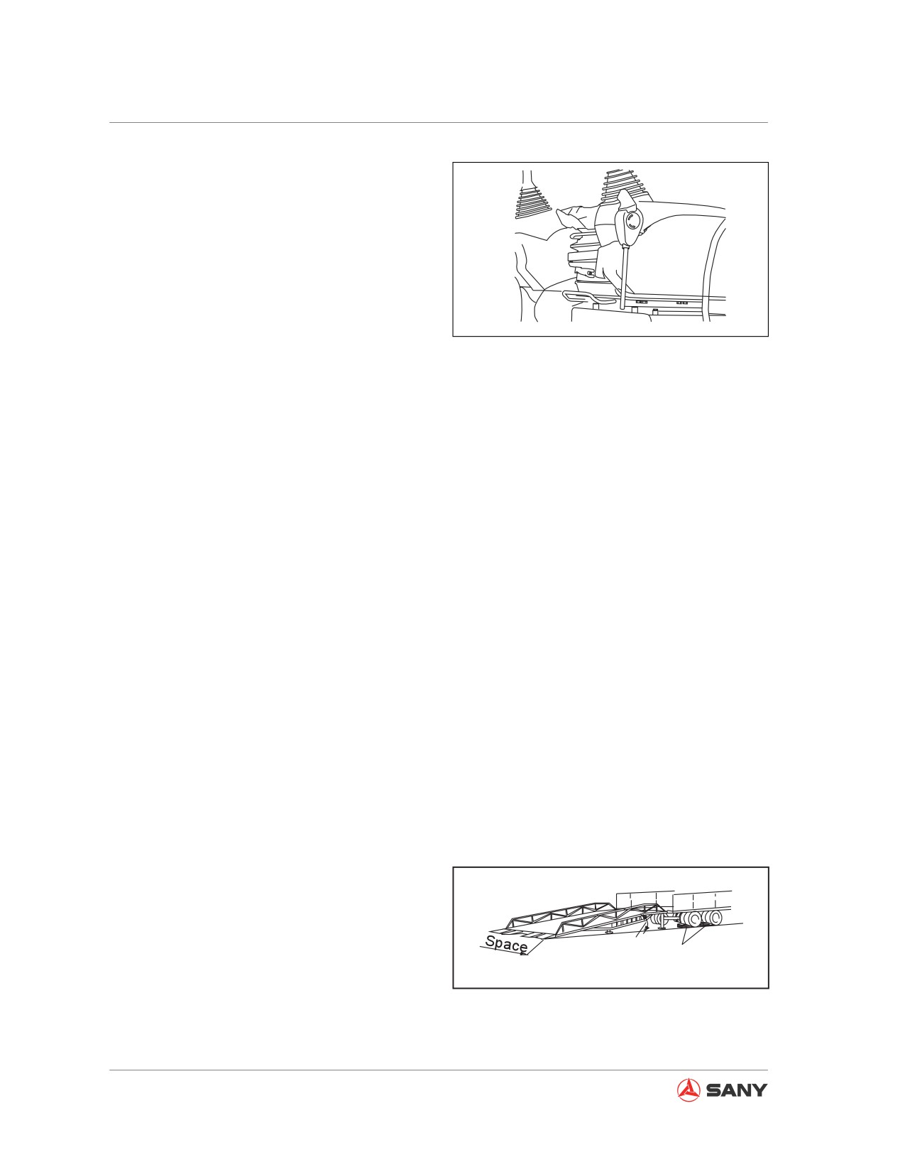
6. Place hydraulic lockout control to the
2-51
Safety
LOCK position.
7. Remove ignition key.
8. Close the windows and the cab door.
Locked
9. Lock all access doors, boxes and cham-
bers.
CZ335-1102057
When leaving your machine, face the machine
Fig. 2-76
and maintain a three-point contact with it. Nev-
er jump off the machine.
Be careful with slippery track, step and hand-
holds when dismounting the machine.
2.4.4 Transportation
2.4.4.1 Loading and unloading the machine
Improper loading and unloading of the ma-
chine may cause it to fall or tip over. Follow
the procedures below:
● Load or unload the machine only on a solid
and flat surface. Keep it a safe distance
away from road sides or a cliff.
● Keep on-lookers away.
● Use an access ramp with enough strength.
Make sure that the width, length and thick-
ness of the access ramp is capable of pro-
viding a safe loading/unloading operation
(at an angle 15°).
● Make sure the access ramp is free from
grease, oil, water and debris. Clean the
track if necessary. Be extremely careful
when loading or unloading the machine in
rainy or snowy weather.
Max. Angle15°
Blocks
● Never load or unload the machine using
CZ335-1102058
the force of work equipment, which may
Fig. 2-77
cause the machine to fall or tip over.
● Run the engine at low speed and drive
slowly.
2-52
Safety
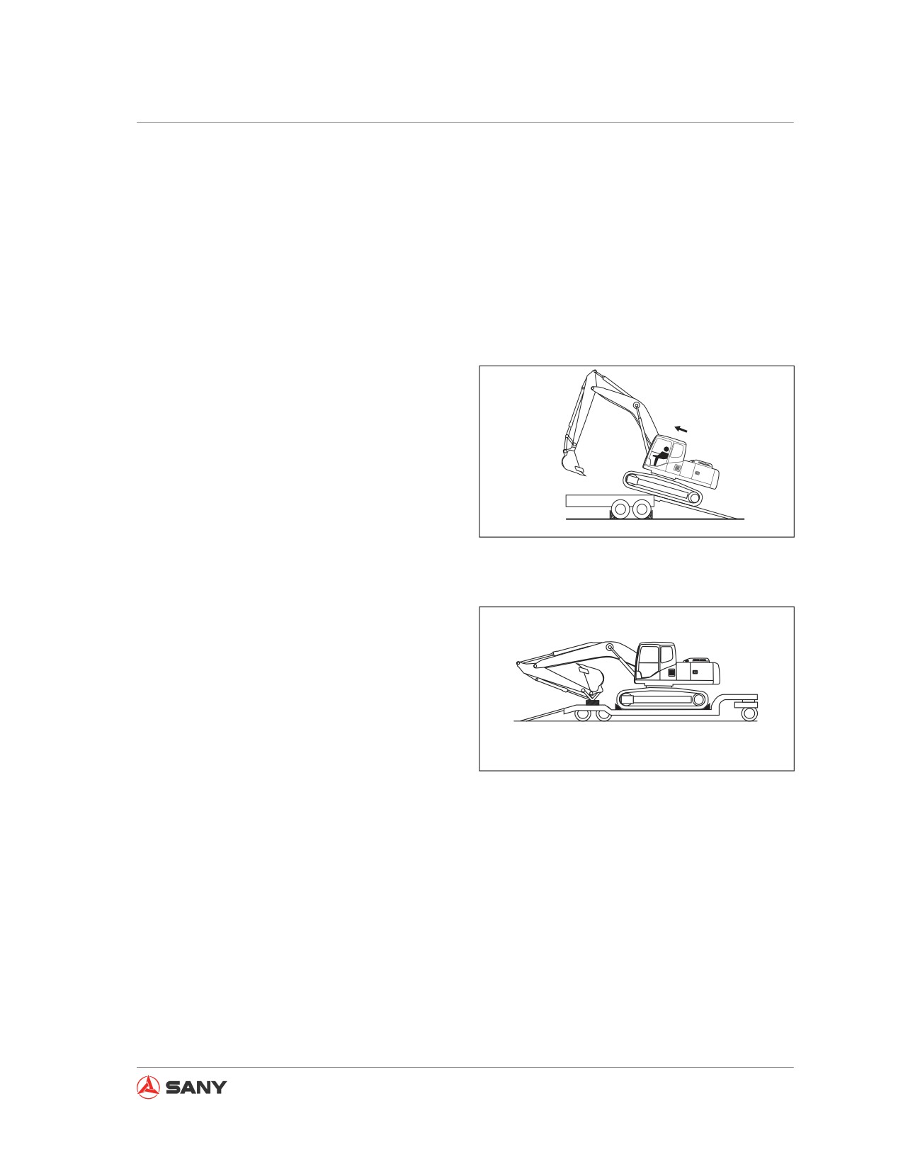
●
Place the work equipment straight forward.
●
Never operate any control levers other
than the travel control lever when the ma-
chine is driving up the ramp.
●
Never reposition the machine on the ac-
cess ramp. If necessary, drive it off the
ramp, reposition, and get on the ramp
again.
●
Gravity center of the machine may alter
when it passes the jointing area between
the ramp and the trailer. The machine may
tilt at this moment. Travel slowly when the
machine is on the joint area.
●
When loading or unloading the machine on
a platform, make sure the platform has ad-
equate width, strength and a proper grade.
●
The trailer may become less stable with
CZ335-1102059
the machine on it. Retract the work equip-
ment and swing the upper structure slowly.
Fig.
2-78
●
Once the machine is loaded, lock the cab
door. Otherwise, it may swing open during
transportation.
●
Secure the machine with chains and
chocks.
●
Secure all work equipment, lower the buck-
et, the arm and the boom, and place them
in position for transport.
CZ335-1102060
2.4.4.2 Transporting the machine
Fig.
2-79
Observe the following items when transporting
the machine:
● Note the dimension of the trailer and the
machine, especially the height. Watch out
for barriers overhead and in narrow pas-
sages.
● Check the structure and strength of a
bridge before crossing it. Obey local traf-
fic regulations and traffic police directions
when transporting the machine on high-
ways.
2-53
Safety
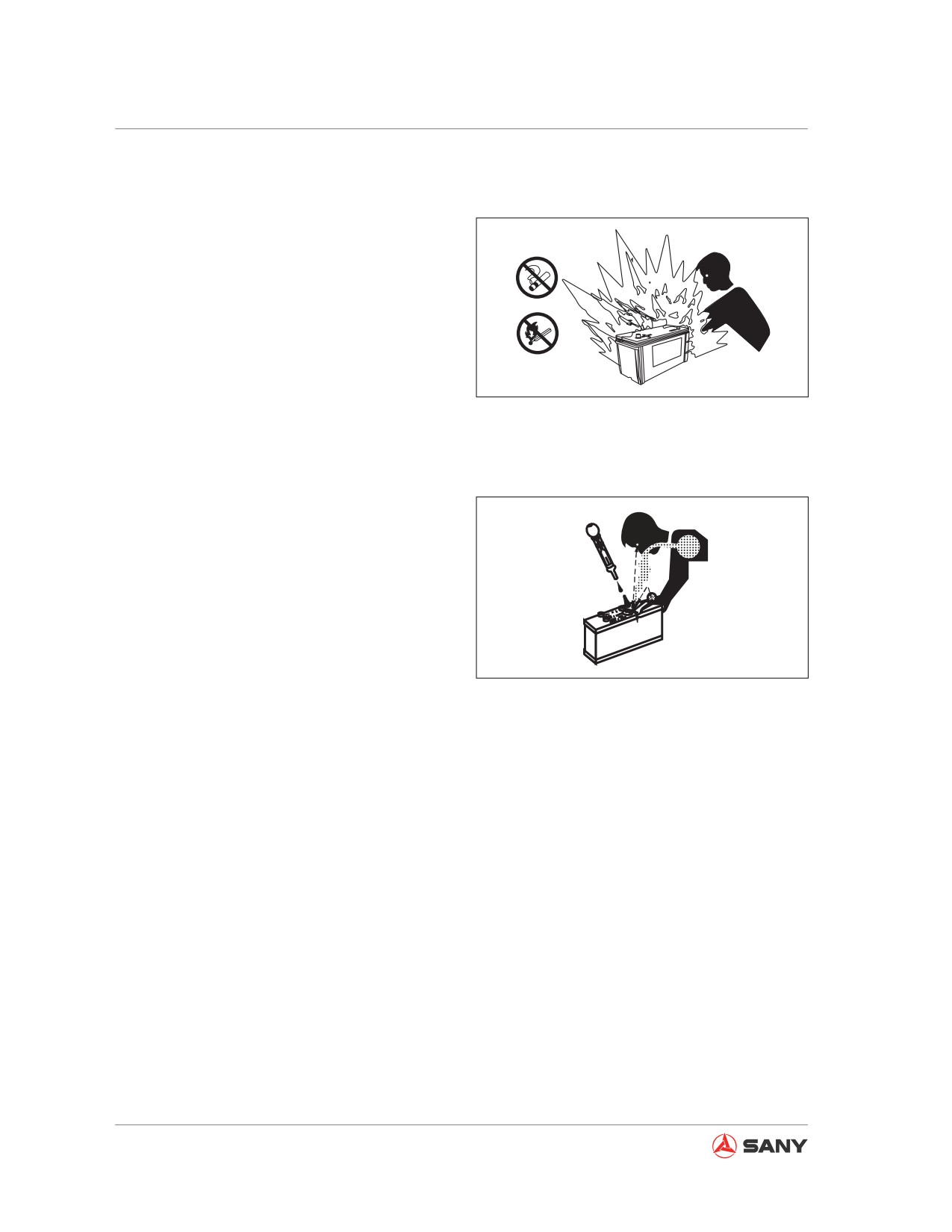
2.4.5 Battery
Electrolyte contains sulfuric acid, which gives
off flammable and explosive gases. Improper
handling may cause personal injury or fire.
Observe the instructions below when handling
battery:
● Never smoke or use fire near a battery.
● Turn the engine ignition key to the OFF po-
CZ335-1102061
sition before working on the battery.
Fig. 2-80
● Wear safety glasses and rubber gloves
when handling battery.
● Electrolyte is a strong acid. If electrolyte
contacts your clothing or skin, flush imme-
diately with plenty of water. Electrolyte may
cause blindness if it contacts your eyes.
Flush immediately with plenty of clean wa-
ter under such circumstances and seek
medical treatment.
CZ335-1102062
Fig. 2-81
To avoid battery-induced explosion, observe
the following precautions:
● Never allow tools and other metal parts to
contact with battery terminals. Keep tools
or metal parts away from batteries.
● Stop the engine and wait for one minute
before you proceed. Always disconnect the
grounding terminal (negative(-) ) first. To
connect battery cables, always begin with
the positive (+) terminal, and then connect
the negative (-) terminal. Ensure all termi-
nals are securely connected.
● Battery temperature rises when it is be-
ing charged. When battery temperature
exceeds 45°C, stop charging and wait till
it is at ambient temperature. Reduce the
charging current by half and continue the
2-54
Safety
charging process.
● A battery being charged may give off flam-
mable gases. Before charging a battery,
remove it from the undercarriage, put it in
well-ventilated area and remove the cap.
● If acid squirts out of battery vent during
A
charging, stop charging immediately.
B
● Never smoke and keep flames or sparks
out when charging.
● When the battery has been fully charged, a
C
green indicator will be on. Stop the charg-
ing process at this time.
CZ335-1102063
● Restore the battery cover after charging.
Fig. 2-82
● Put the battery back to its original position.
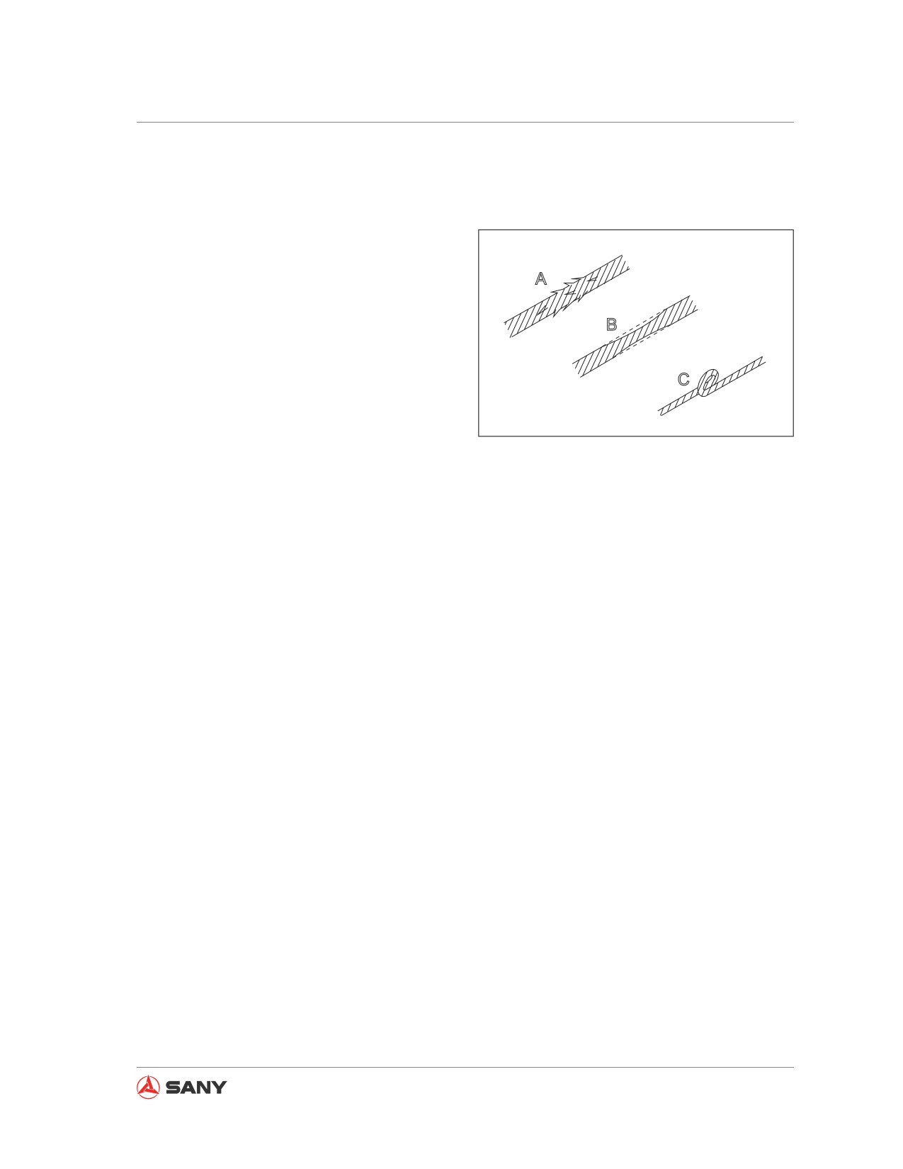
When towing a damaged machine, improper
operation or use of unacceptable wire cable
could lead to serious accident:
● Never tow the machine on a slope.
● Wear protective gloves and a had hat
when using wire ropes.
● Check the strength of wire cable and make
sure it could bear the weight of machine.
● Never use ropes with broken wires (A), re-
duced diameter (B) and twisting (C). Such
ropes may break when towing.
● Never stand between the towing machine
and the towed machine during towing op-
eration.
● Operate the machine slowly. Never add
load to the wire cable suddenly.
2-55
Safety
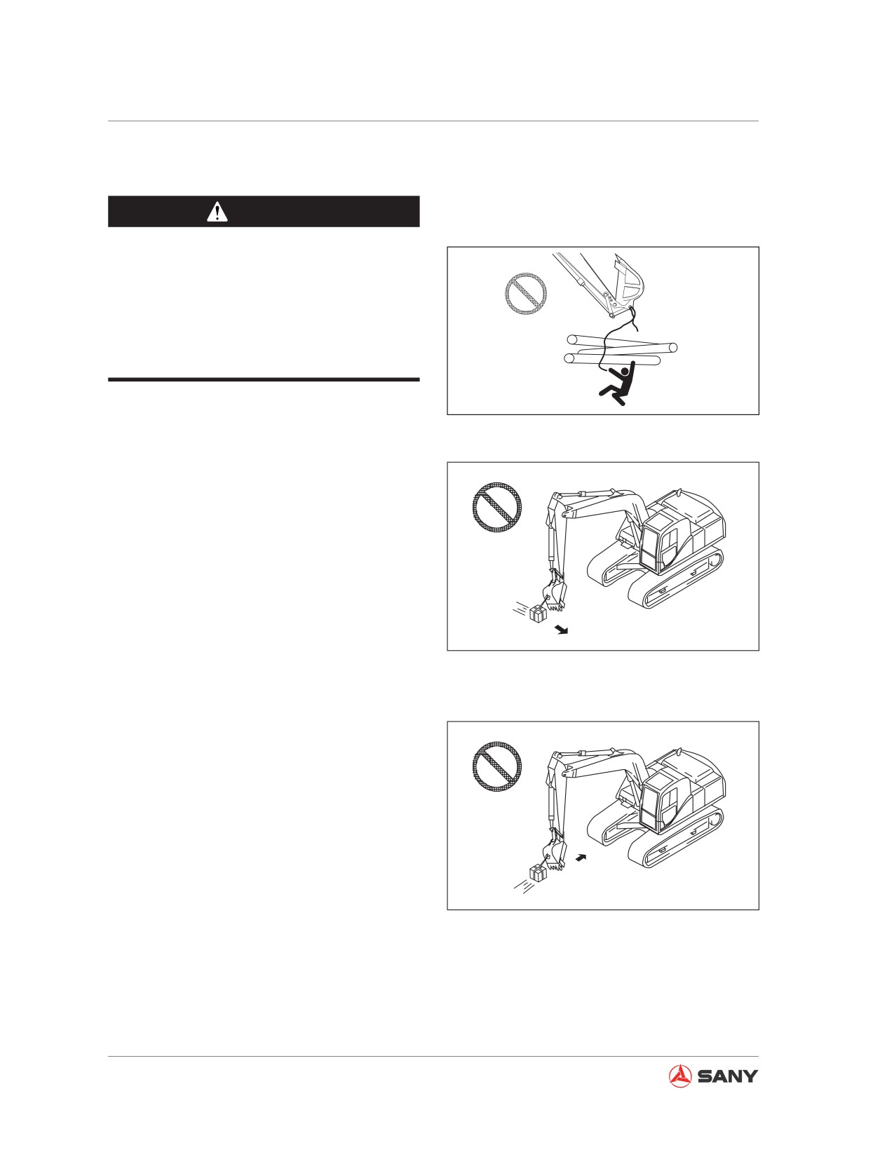
2.4.6 Lifting objects with the machine
WARNING
● Overload is dangerous and can cause
serious injury and death.
● Make sure the load is within the loading
range and working radius of the ma-
chine.
CZ335-1102064
●
Nobody is allowed to enter the working
area.
Fig. 2-83
●
Confirm all signals to be used and assign a
signalman before operation.
●
Lift a load on a flat surface to prevent the
machine from tilting or tipping over.
●
Never use chains, wire ropes, shackles
and slings that are damaged.
●
Anchor wire ropes or slings onto the desig-
nated lifting lug. Never attach the shackle
or sling onto the bucket tips. Loosened
CZ335-1102065
bucket tips could cause the load to fall.
Fig. 2-84
●
Never leave the operator seat when lifting
is in progress.
●
To prevent the load from hitting any person
or building, inspect carefully the machine
surroundings before swinging or operating
the work equipment.
●
Never swing or operate the work equip-
ment suddenly. This may cause the load
to drift and the machine to tip over. Use a
drag rope if necessary.
●
Never use the work equipment or the
CZ335-1102066
swing force to drag the load in any direc-
tion. The work equipment will jerk if the
Fig. 2-85
shackle breaks and the load comes free,
resulting in serious personal injury.
2-56
Safety
2.5 Precautions for Maintenance
2.5.1 Prior-maintenance precautions
To prevent accidents:
● Understand maintenance procedure before
operation.
● Keep a clean and dry working area.
● Never spray water or steam in the cab.
● Never add lubricant and carry out other
maintenance work when your machine is
moving.
● Keep your hands, feet and clothing away
from rotating parts.
2.5.2 Select a working area
● For maintenance work, select a clean flat
area with plenty of space, ample sunlight
and good ventilation.
● Clean the working area by removing fuel,
lubricant and water, and covering slippery
ground with sand or other absorptive mate-
rials.
● Never leave your hammer or other tools at
the working area.
● If a clean, tidy working area cannot be
guaranteed, there would be danger of tip-
ping, thus resulting in personal injury.
2-57
Safety
2.5.3 Preparing the machine
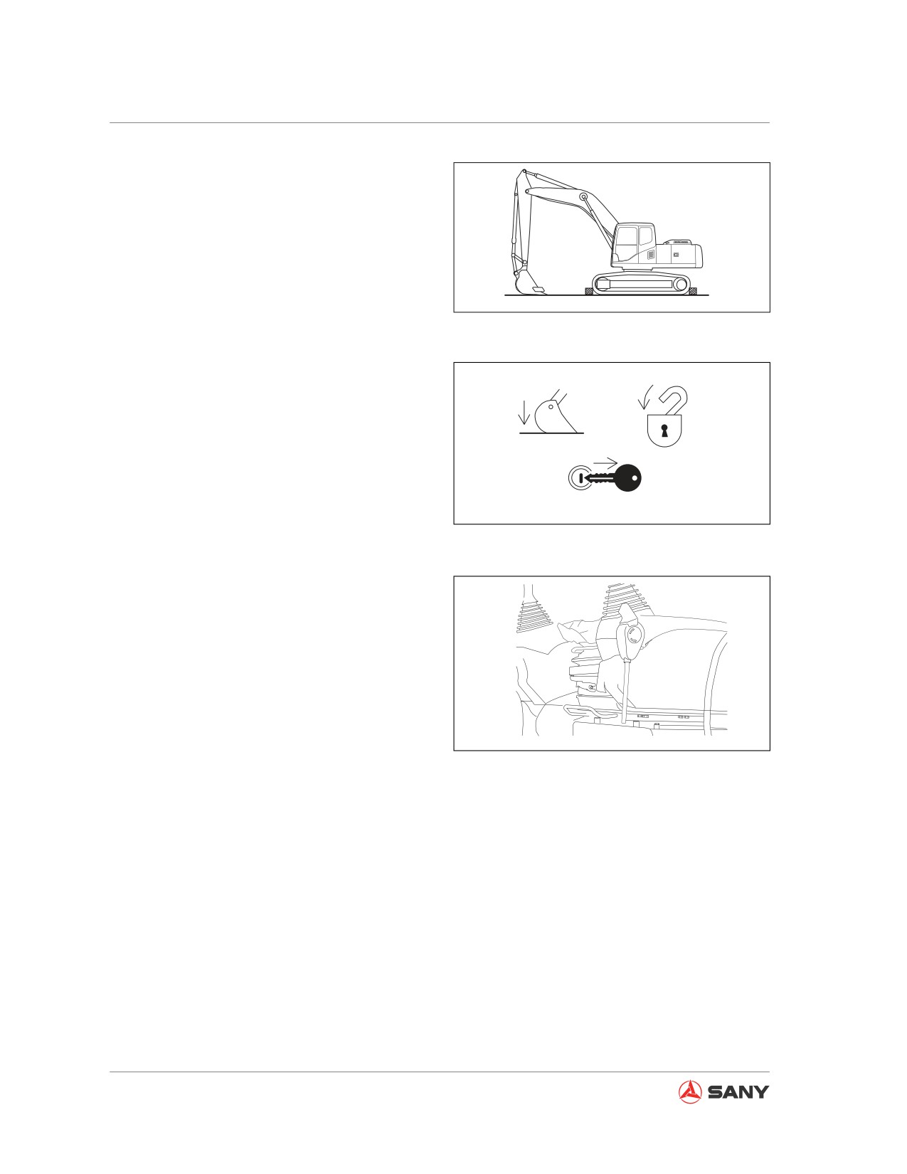
Before maintaining the machine:
● Park the machine on solid and flat ground.
● Lower the bucket to the ground.
● Place blocks under the tracks to prevent
CZ335-1102073
movement of the machine.
Fig. 2-86
● Turn the fuel control dial to first gear. Run
the engine at low speed for 5 minutes.
● Turn the start switch to OFF position and
stop the engine.
● Turn the start switch to the ON position.
Operate the control levers 2 or 3 times in
all directions to relieve internal pressure of
the hydraulic system.
CZ335-1102074
● Remove the key from the switch.
Fig. 2-87
● Place the hydraulic lockout control to the
LOCK position.
Locked
CZ335-1102075
Fig. 2-88
2-58
Safety
2.5.4 Preparing yourself
Only approved personnel can maintain or
repair the machine. An observer may be as-
signed if necessary.
●
Wear protective clothing and shoes neces-
sary for the job.
●
Wear rubber apron and rubber gloves
when handling corrosive materials. Wear
CZ335-1102069
heavy gloves when handling wooden ma-
terials, wire ropes or sharp-edged metals.
Fig.
2-89
●
Wear a face shield when removing spring
or elastic parts, or adding acid to battery.
Wear safety hat and goggles when you
weld or cut with a torch.
●
Never carry out grinding, flame cutting or
welding without an aspirator and ventilation
equipment.
●
Loud noise may impair your hearing per-
manent or temporary. When maintaining
the engine, wear ear covers or ear plugs if
CZ335-1102070
you have to work in loud noise for a long
Fig.
2-90
time.
●
When using a hammer to strike hard metal
parts such as pin, bucket teeth, cutting
edge or shaft, the flying of parts and metal
pieces may cause bodily injury. Therefore,
wear goggles and gloves and ensure the
surrounding area is clear of any other peo-
ple.
●
When compressed air is used for cleaning,
flying particles may cause personal injury.
In this case, wear goggles, dust-preventive
mask, gloves and other protective gear.
CZ335-1102071
Fig.
2-91
2-59
Safety
2.5.5 Lock-out and tag-out
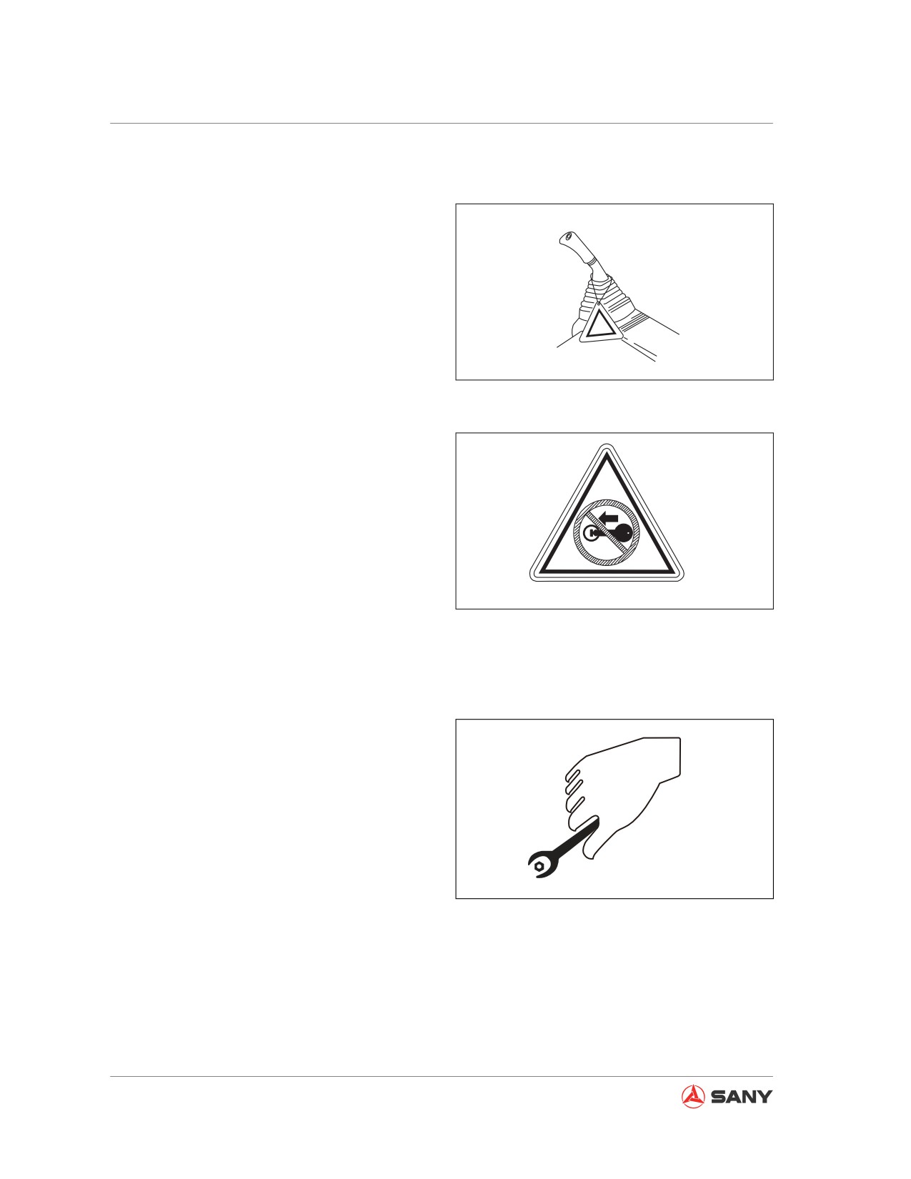
● When maintenance is underway, starting
the engine or moving the control levers or
pedals could lead to serious accident.
● Before maintenance, attach a Never OP-
ERATE tag or similar sign to the machine's
start switch or control levers to warn others
that this machine is under maintenance.
● Attach other warning tags around the ma-
CZ335-1102067
chine if necessary.
Fig. 2-92
CZ335-1102068
Fig. 2-93
2.5.6 Using proper tools
Use proper tools and use them correctly. Us-
ing damaged, inferior, defective, temporary
tools or using the tools incorrectly could lead
to serious accidents.
CZ335-1102072
Fig. 2-94
2-60
Safety
2.5.7 Maintenance with engine running
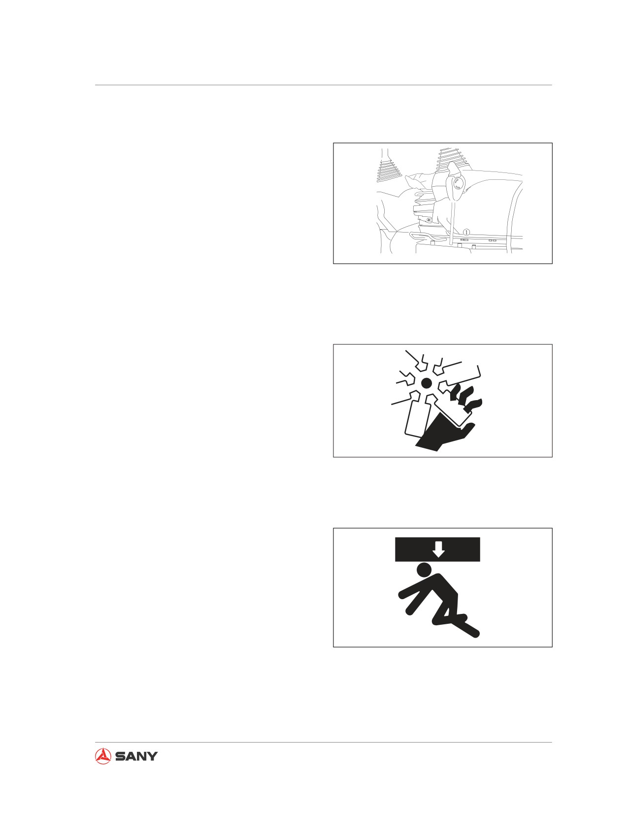
To prevent injury, no maintenance shall be car-
ried out when the engine is running. However,
if maintenance has to be done on a running
engine, at least two worker are needed to car-
ry out the maintenance.
Locked
● One of the workers shall stay in the opera-
tor seat ready to shut down the engine at
any time. All the workers involved shall
CZ335-1102076
keep in touch.
Fig.
2-95
● Place the hydraulic lockout control to the
LOCK position to prevent movement of
work equipment.
● Pay special attention to rotating parts like
fan and fan belt.
● Never leave or insert any tool or other ob-
jects in the fan or the fan belt, which may
cause the parts to break or fly.
● Never touch any control lever. If one of the
control levers must be used, give signal
to other workers and warn them to move
CZ335-1102077
quickly to a safe area.
Fig.
2-96
2.5.8 Working under the machine
● Never carry out maintenance before the
machine is well supported.
● Lower the work equipment to the ground
before maintaining the machine.
● If the machine or work equipment has to
be lifted for maintenance, blocks or sup-
ports that are strong enough to support
the machine or work equipment should be
CZ335-1102078
used. Never use slag bricks, empty tires
or stands to support the machine. These
Fig.
2-97
things may collapse under continuing load.
Never use single jack to support the ma-
chine.
2-61
Safety
● If the track shoes are lifted and the ma-
chine is solely supported by the work
equipment, it is very dangerous to work
under the machine. In case of failure of hy-
draulic pipe or accidental touch of control
lever, the work equipment or machine may
fall suddenly, causing injury or death. Nev-
er work under the machine if it is not firmly
supported with blocks or supports.
2.5.9 Track maintenance
WARNING
Never strike the recoil springs of the track.
Recoil springs are under immense pres-
sure and spring rupture may cause bodily
injury. Never remove any spring when it is
compressed.
● Dry rubbing of pin against bushing may
produces extreme heat. Wear protective
gloves to avoid burns.
● Maintain proper track tension. When work-
ing on mud- or snow-covered ground, mud
or snow may attach to track components
and causes over tension. Adjust track ten-
sion properly.
● Check for loosened or broken track shoes.
Check the pins and bushings for wear or
damages. Check the track rollers and car-
rier rollers.
2-62
Safety
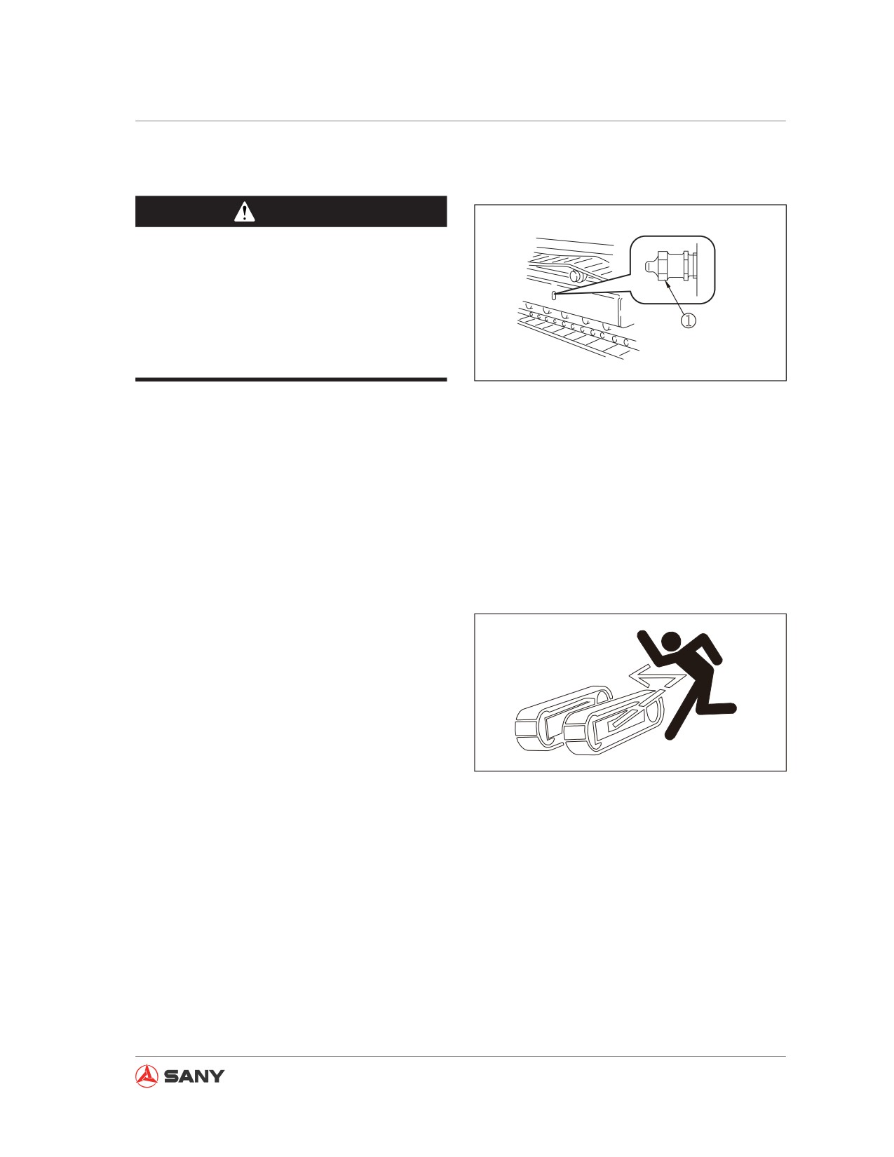
2.5.10 Track tension adjustment precautions
WARNING
Grease is injected into track tension ad-
justment system under high pressure. Fail-
ure to observe specified maintenance pro-
cedures may cause the grease discharge
1
plug to eject and cause serious injury and
damage.
CZ335-1102080
Fig. 2-98
● When loosening the grease discharge plug
(1) to reduce track tension, the plug shall
be unscrewed slowly for no more than one
turn.
● Keep your face, hand, foot or any other
body part away from the grease discharge
plug.
2.5.11 Recoil spring
The recoil springs are used to reduce the im-
pact of tension rollers. It includes a high pres-
sure spring, which may fly out and cause seri-
ous injury or death if removed improperly.
If it has to be removed, contact your Sany dis-
tributor.
CZ335-1102081
Fig. 2-99
2-63
Safety
2.5.12 Welding operation
Welding operation may lead to fire or electro-
cution. Only qualified welders are allowed to
conduct welding operation using proper equip-
ment.
2.5.13 High-pressure hoses
If oil leaks from high-pressure hose, fault or
even fire may occur. If any bolt on hose is
loose, stop operation and tighten it to specified
torque. In case of hose damage, stop opera-
tion immediately and contact Sany HM autho-
rized dealer.
Replace the hose immediately in case of the
following problems:
● Damage or leak of hydraulic hose fitting
● Damage or break of outer cover, or ex-
posed steel wires of reinforcement layer
● Ballooning outer cover in some places
● Distortion or crushing of movable parts
● Impurities in outer cover
2-64
Safety
2.5.14 Pressurized fluid
The hydraulic system is always under pres-
sure. Make sure pressure in hydraulic circuits
has been relieved before checking or replac-
ing the lines. Residual pressure in the circuit
may cause serious accidents.
●
Release system pressure before maintain-
ing the hydraulic system: 1) Remove the
butterfly nut of the vent valve and press
the venting button to release the internal
pressure of the hydraulic tank; 2) Turn the
start switch to ON position within 15 sec-
onds after engine shutdown and place the
hydraulic lockout control to FREE position.
Move the control levers to all directions to
release the pressure in the accumulator.
Open fire is not allowed around the hydrau-
lic system. Remove splashed hydraulic oil
as quickly as possible.
●
Diesel oil or pressurized hydraulic oil can
penetrate skin or eyes, causing serious
injury, blindness or death. It is hard to find
the leaking of hydraulic oil with naked eyes.
CZ335-1102082
A cardboard or wooden board is necessary
for checking for leaks. Never touch leaking
Fig. 2-100
liquid with bare hand. Wear face shield or
safety goggles to protect your eyes. If any
liquid penetrates your skin, flush with clean
water immediately and get medical atten-
tion as soon as possible.
●
The fuel lines are under high pressure
when the engine is running. When check-
ing or servicing the fuel system, shut down
the engine and wait for 30 seconds till in-
ternal pressure drops before operation.
2-65
Safety
2.5.15 Hot cooling system
WARNING
Touching hot high-pressure coolant may
cause serious injury.
When engine temperature rises, pressure of
the cooling system increases. Before remov-
ing the radiator cover, stop the engine and
let the system cool down. The radiator cover
could only be removed after the coolant in it
CZ215L-1102001
has cooled down.
Fig. 2-101
2.5.16 Air-conditioning system
WARNING
● Refrigerant R134 a is a harmless gas
under room temperature. It will change
into highly toxic gas when burning.
● Refrigerant getting into eyes may cause
blindness. It may cause frostbite if
splashed on your skin.
● Keep fire source away when servicing air-
conditioning system.
● In maintenance of air-conditioning system,
observe the instruction on the refrigerant
cylinder and use it correctly. The type of
refrigerant is R134a. Use of other refriger-
ants may damage the air-conditioning sys-
tem.
CZ335-1102083
● Obey local material disposal regulations.
Fig. 2-102
Never discharge refrigerant directly into the
air.
2-66
Safety
2.5.17 High voltage precautions
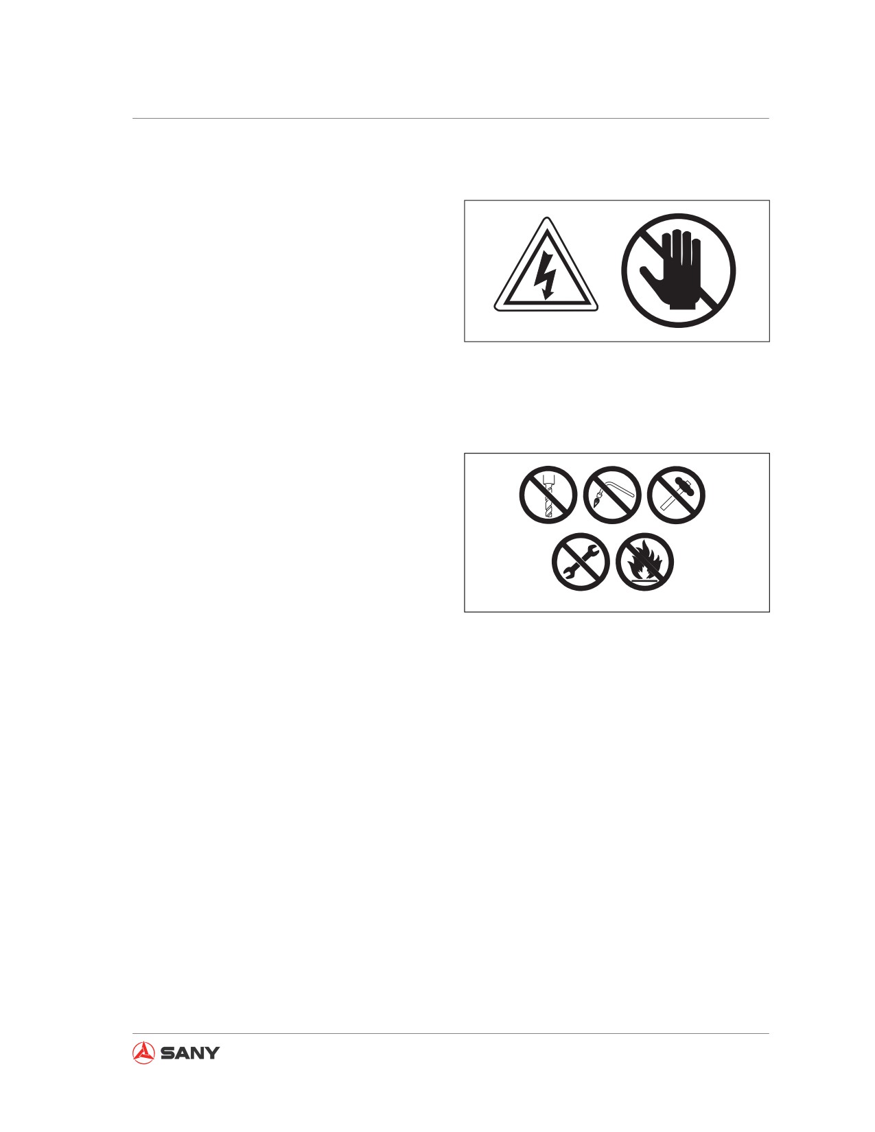
When the engine is running or has just been
shut down, high voltage can occur in fuel in-
jector terminal and engine controller. Since
there is danger of electrocution, never touch
fuel injector or interior of engine controller.
Please contact Sany distributor if you have to
CZ335-1102084
access fuel injector terminal or interior of en-
gine controller.
Fig. 2-103
2.5.18 Accumulator
Accumulator contains highly pressurized ni-
trogen. Improper operation of accumulator
can cause explosion and serious accidents.
Therefore, the following precautions must be
observed:
● Never disassemble the accumulator.
● Never let the accumulator be near a fire
CZ335-1102085
source or exposed in flame.
Fig. 2-104
● Never punch, weld or flame-cut on accu-
mulator.
● Never strike or roll the accumulator, or let it
bear any impact.
● The gas must be released when disposing
of the accumulator. Contact Sany distribu-
tor for this disposal.
2-67

Safety
2.5.19 Avoiding fire and explosion
DANGER
Never smoke when handling the fuel or
maintaining the fuel system. The gases in
empty fuel tank can cause explosion eas-
ily. Never carry out flame-cutting or weld-
ing operation on fuel pipe, fuel tank or fuel
vessels, which can lead to fire, explosion,
injury or death.
●
Then engine must be shut down and elec-
trical equipment must be switched off when
refueling the tank. Be extremely care-
ful when adding fuel to a hot engine. No
sparks shall occur around the grounding
nozzle.
●
Handle all solvents and dry chemicals in a
place with good ventilation according to the
steps indicated on vessel.
CZ335-1102014
●
Clean the machine of all dust and residu-
Fig. 2-105
als. Never place greasy rag or other flam-
mable materials on machine.
●
When cleaning the parts and components,
use nonflammable solvents instead of gas-
oline, diesel oil or other flammable fluids.
●
Store flammable liquids and materials in
suitable vessels as required by safety laws
and regulations.
●
Check fire extinguishers, fire-fighting sys-
tem and fire detectors (if equipment) and
make sure they are ready for use.
2-68
Safety
2.5.20 Regular replacement of safety-
related parts
WARNING
Safety-related parts are important for safe-
ty of you and your machine. Failure to re-
place them at specified intervals may lead
to personal injury, death or serious dam-
age.
● Safety-related parts such as hoses and
seat belt must be replaced regularly for
the consideration of operating the machine
safely in a long term.
● Materials of some parts may deteriorate
naturally when exceeding specific time
limit. Repeated use may lead to deteriora-
tion, wear and damage, hence the acci-
dents and serious injury. Through merely
visual inspection or feel it is hard to find out
how long the parts could serve. Therefore,
regular replacement is necessary.
● Repair or replace any safety parts once
found defective regardless of its service
time.
2-69
Safety
2.5.21 Maintenance operation
● Check all parts and replace the worn, bro-
ken and damaged parts during repairing
operation. Over-worn and over-damaged
parts may fail in operation and cause injury
and death. Replace damaged or illegible
signs and marks.
● Tighten all fasteners and connectors to
specified torque.
● Install all guards, covers and hoods after
repair and service. Replace or repair dam-
aged guards. Only the type of hydraulic oil
approved or recommended by Sany should
be used to make up the hydraulic system.
● Start the engine and check for any leaks
(check the hydraulic system), and operate
all control devices to be sure of their prop-
er functioning. Make road test if necessary.
Shut down the engine and check the work
you have done (see if there are missing
pins, gaskets and nuts). Check again all
hydraulic oil levels before operation.
2-70
Safety
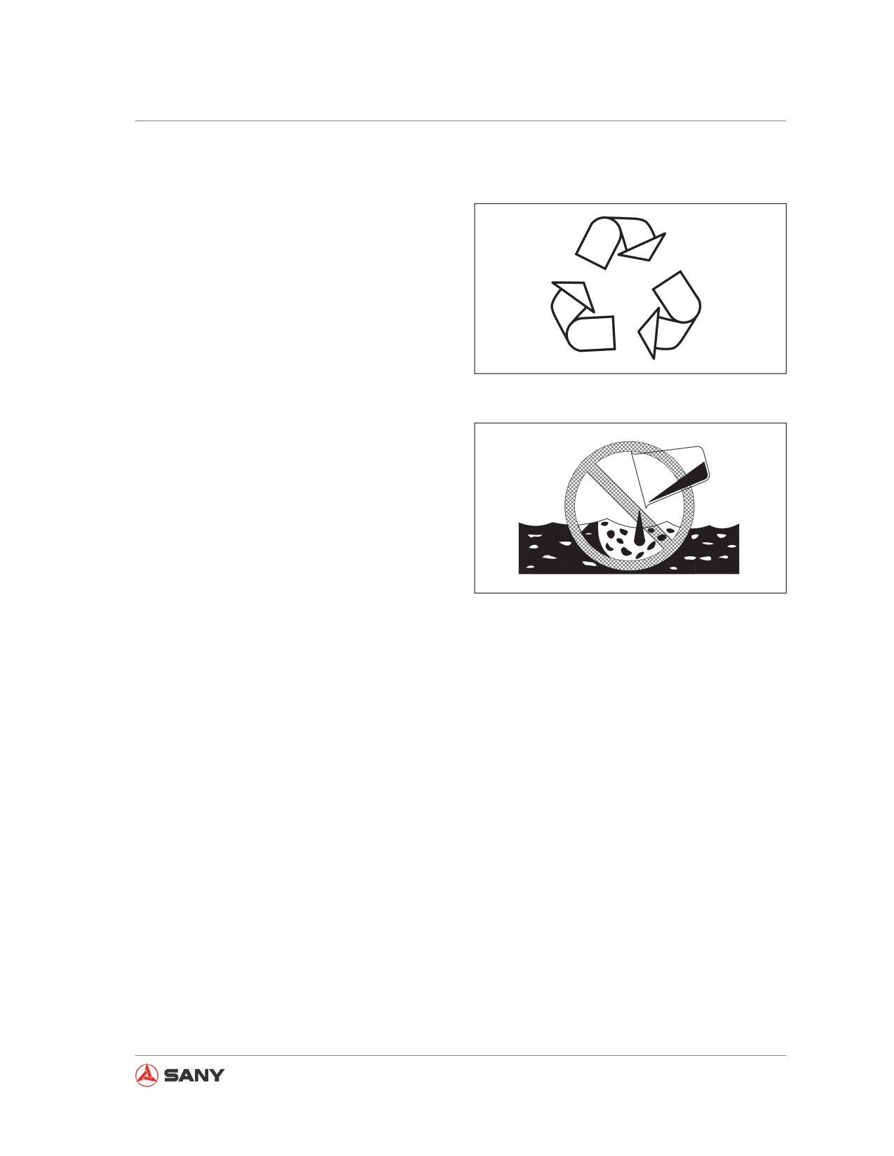
2.5.22 Proper disposal of wastes
Improper disposal of wastes harms the envi-
ronment and ecology. Consult local environ-
mental protection department or Sany dis-
tributors for methods of recycling and waste
disposal.
● Potential harmful substances used in Sany
products include hydraulic oil, fuel, cooling
liquid, refrigerant, filter and batteries etc..
CZ335-1102086
● Use leak-proof vessels to hold discharged
Fig.
2-106
fluids. Never use food or beverage contain-
ers.
● Never dump waste fluids directly to the
ground, sewage or water source.
● Leaking of refrigerant from air conditioner
can spoil the atmosphere of the globe.
Related laws and regulations must be fol-
lowed to recover or regenerate the refriger-
ant.
CZ335-1102087
Fig.
2-107
2-71
Safety
2-72
System Functions
System Functions
3 System Functions
3.1
Machine Overview
3-5
3.2
Machine Controls
3-6
3.3
Monitor
3-7
3.3.1 Monitor introduction
3-7
3.3.2 System information and operation
3-10
3.3.2.1 Main Page
3-10
3.3.2.2 System Information
3-12
3.3.2.3 Time Setup
3-13
3.3.2.4 Main Menu
3-14
3.3.2.5 Engine & Throttle Signals
3-15
3.3.2.6 Main Pump Signals
3-15
3.3.2.7 Input Switch Signals
3-16
3.3.2.8 Output Switch Signals
3-16
3.3.2.9 Machine Configuration
3-17
3.3.2.10 Failure codes
3-17
3.3.2.11 Maintenance Information
3-18
3.3.2.12 Engine Speed Calibration
3-23
3.3.2.13 Language Selection
3-25
3.3.2.14 GPS Monitoring Information
3-26
3.3.2.15 System Setup
3-27
3.3.2.16 Machine configuration setup
3-28
3.3.2.17 Coolant Temperature
3-29
3.3.2.18 Service Call
3-30
3.4
Switches
3-31
3.4.2.1 Start switch
3-32
3-1
System Functions
3.4.2.2 Fuel control dial
3-33
3.4.2.3 Work lamp switch
3-33
3.4.2.4 Wiper switch
3-35
3.4.2.5 Washer switch
3-36
3.4.2.6 Head lamp switch
3-36
3.4.2.7 Horn switch
3-37
3.4.2.8 Cab lamp
3-37
3.4.2.9 Cigar lighter
3-37
3.4.2.10 Preheat switch (only for SY135C8M)
3-38
3.4.2.11 Alternator indicator
3-38
3.5
Control levers and pedals
3-39
3.5.1 Hydraulic lockout control
3-40
3.5.2 Travel controls
3-41
3.5.3 Joystick controls
3-42
3.6
Roof Hatch
3-44
3.6.1 Opening the roof hatch
3-44
3.6.2 Closing the roof hatch
3-44
3.7
Windshield
3-45
3.7.1 Opening the window
3-45
3.7.2 Closing the window
3-48
3.7.3 Removing the lower window
3-50
3.8 Alternate Exit
3-51
3.9 Door Catch
3-52
3.10 Cover/cap with a Latch
3-52
3.10.1 Opening/closing the cover with lock
3-53
3.10.2 Opening/closing the cap with lock
3-54
3.11 Cup Holder
3-55
3.12 Storage Box
3-56
3.13 Literature Bag
3-56
3.14 Ashtray
3-57
3.15 Air Conditioning System
3-58
3.15.1 Control panel
3-58
3.15.2 Operation method
3-64
3.15.3 A/C operation precautions
3-72
3.16 Radio
3-74
3.16.1 Control panel
3-74
3-2
System Functions
3.16.2 Radio operation
3-76
3.17 Auxiliary Power Supply
3-80
3.18 Fuses
3-80
3.19 Fusible Link
3-81
3.20 Controller
3-82
3.21 Toolbox
3-82
3.22 Grease pump frame
3-82
3.23 Fire extinguisher
3-83
3-3
System Functions
3 SYSTEM FUNCTIONS
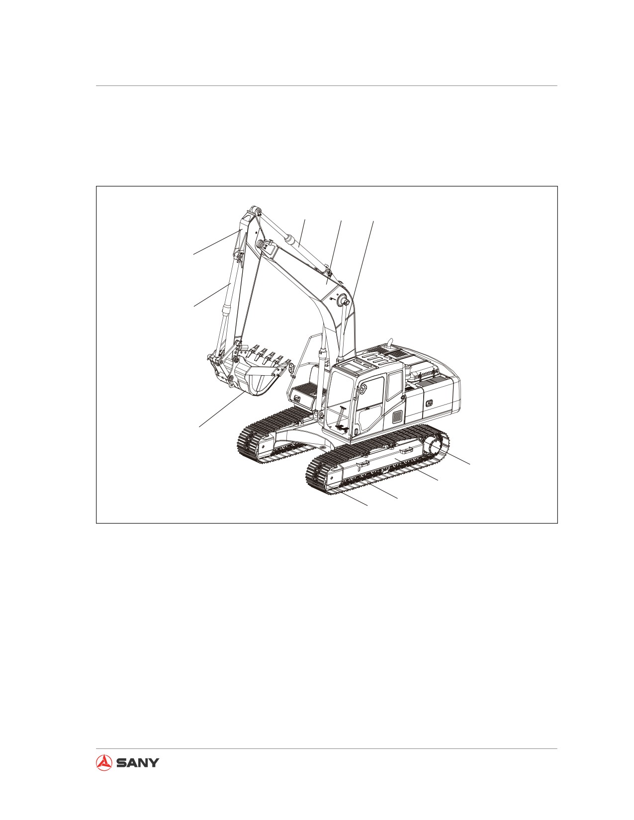
3.1 Machine Overview
4
5
6
3
2
1
7
8
9
10
CZ335-1103001
Fig. 3-1
(1) Bucket
(6) Boom cylinder
(2) Bucket cylinder
(7) Sprocket
(3) Arm
(8) Track frame
(4) Arm cylinder
(9) Track shoe
(5) Boom
(10) Track idler
3-5
System Functions
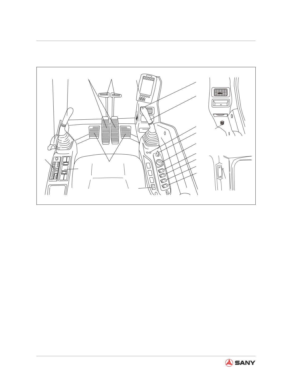
3.2 Machine Controls
3
4
6
7
8
9
10
11
18
12
13
14
2
15
5
16
1
17
19
20
CZ155-1103001
Fig. 3-2
(1) Air conditioner control panel
(11) Indicator lights
(2) Radio control panel
(12) Start switch
(3) Hydraulic lockout control
(13) Fuel control dial
(4) Left joystick control
(14) Work lamp switch
(5) Foot rest
(15) Wiper switch
(6) Travel control pedals
(16) Washer switch
(7) Travel control levers
(17) Head lamp switch
(8) Monitor
(18) Cigar lighter
(9) Horn button
(19) Cab lamp switch
(10) Right joystick control
(20) Preheat switch (only for SY135C8M)
3-6
System Functions
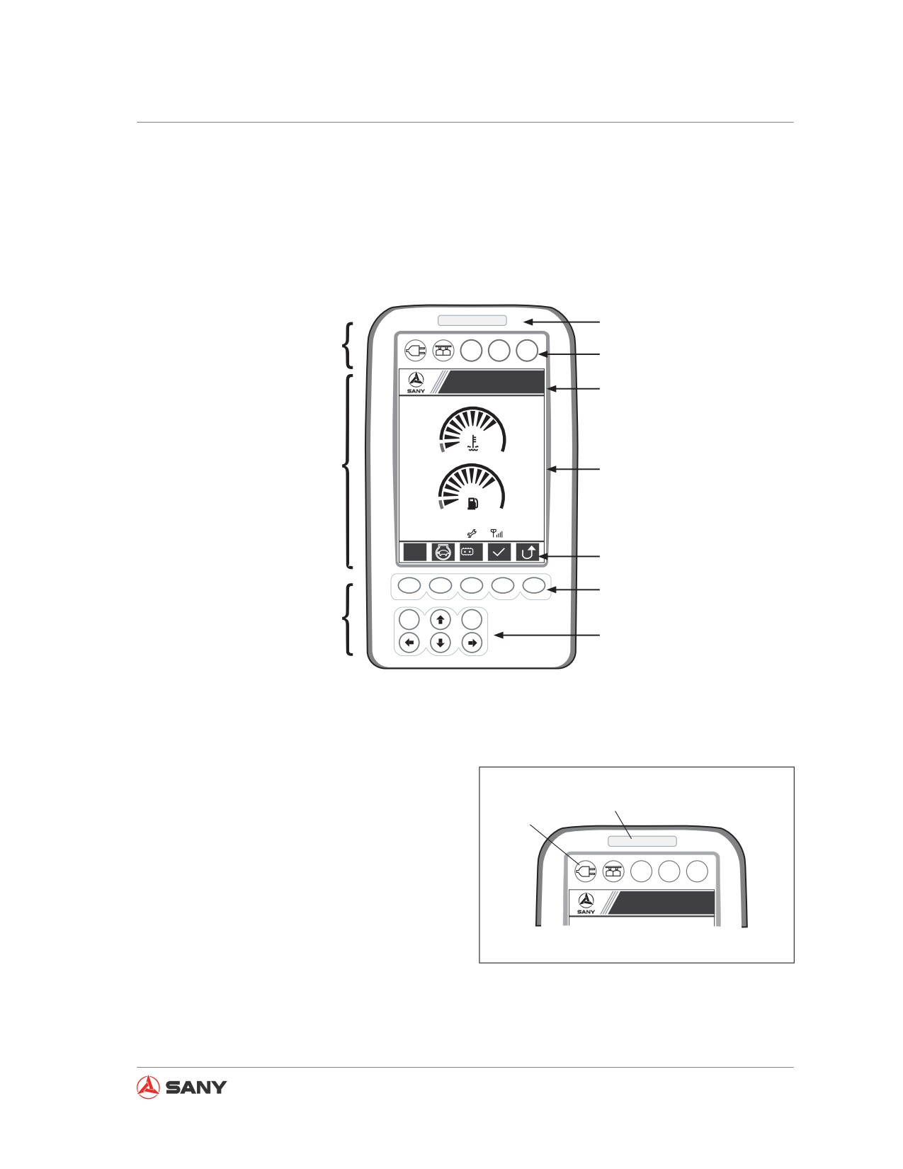
3.3 Monitor
When the start switch is turned to the ON position, the monitor is energized by the battery and
initializes.
An operating monitor looks like below:
Alert indicator
Alert and signal indicators
A B C
Signal indicator
Sany Hydraulic Excavator
Page heading
S
1
Screen
Screen display
09/03/05
0000h 00m
12
12:25:31
S
Lo
Function icons
F1
F2
F3
F4
F5
Function keys
Operation keys
ESC
Enter
Navigation keys
XP1351106027
Fig. 3-3
3.3.1 Monitor introduction
Alert indicator (1)
1
The indicator is on when machine controller
2
detects any fault, warning the user that the
machine has a problem.
A B C
Signal indicators (2)
Sany Hydraulic Excavator
These indicators are designed for power indi-
cation, CAN indication and other signal indi-
XP1351106028a
cation. It is the user’s choice to use any of
Fig. 3-4
them or not.
3-7
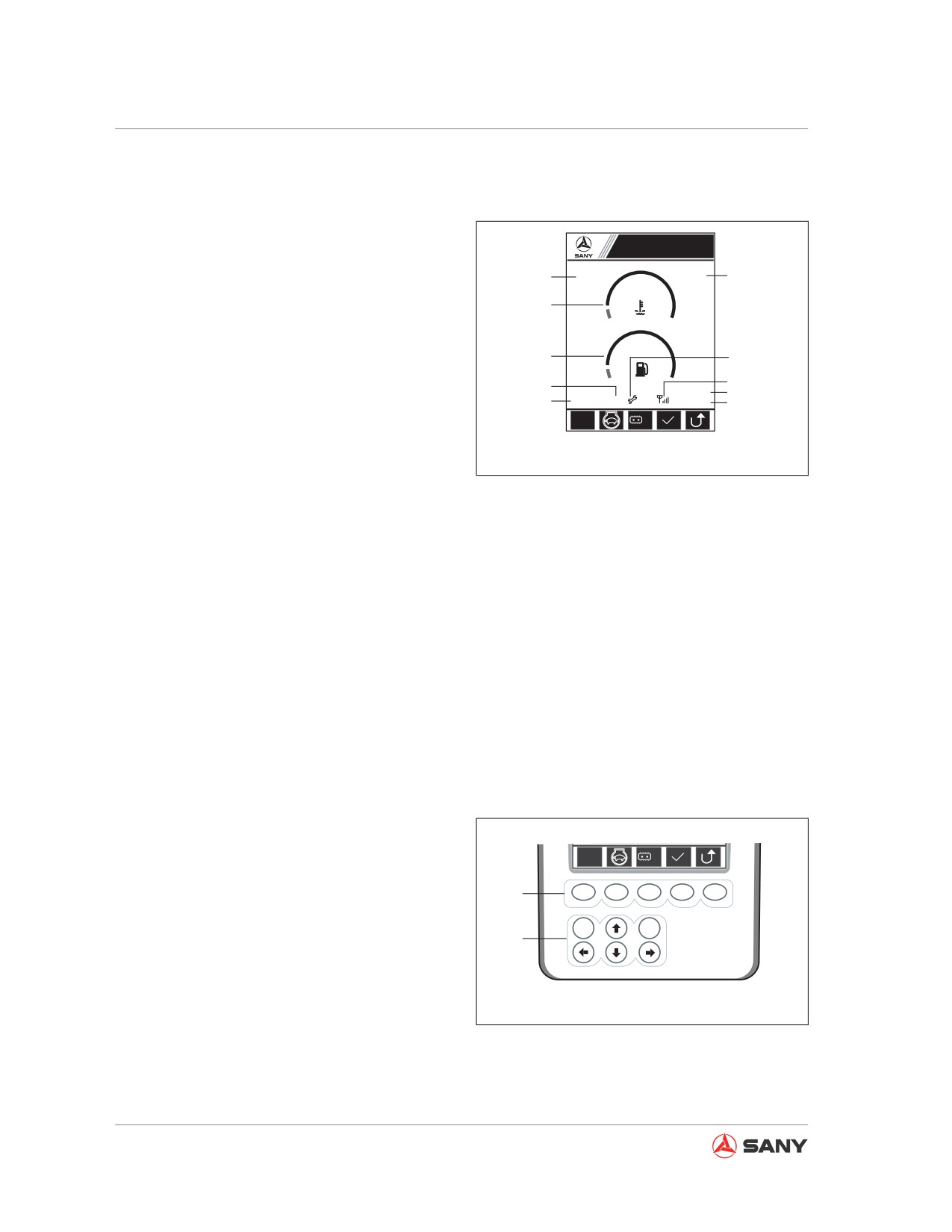
System Functions
LCD display
The LCD display allows you to view system
information like operating parameters, time,
Sany Hydraulic Excavator
and function icons. As shown in Fig. 3-5, the
1
S
1
4
following information will be displayed on the
monitor.
2
1. Working mode (S, H, L or B)
3
7
8
2. Coolant temperature (°C)
5
09/03/05
9
6
0000h 00m
12
12:25:31
10
S
Lo
3. Fuel level (%)
4. Fuel control dial position (1-11)
XP1351106028b
Fig. 3-5
5. Failure code (refreshed every 2s)
6. Engine total operating hours (h/m)
7. Maintenance prompt, if any
8. GPRS signal, indicating whether the com-
munication signal is 1023.
9. System calendar (Y/M/D)
10. System clock (h:m:s)
Operation keys
The operation keys include function keys and
navigation keys.
S
Lo
1. Function keys
1
F1
F2
F3
F4
F5
F1, F2, F3, F4, F5. See Fig. 3-6. Function
ESC
Enter
of each key is defined by the icon displayed
2
above it.
● Function of each key is defined by the icon
above it.
Fig. 3-6
● The key becomes invalid when no icon is
displayed above it.
3-8
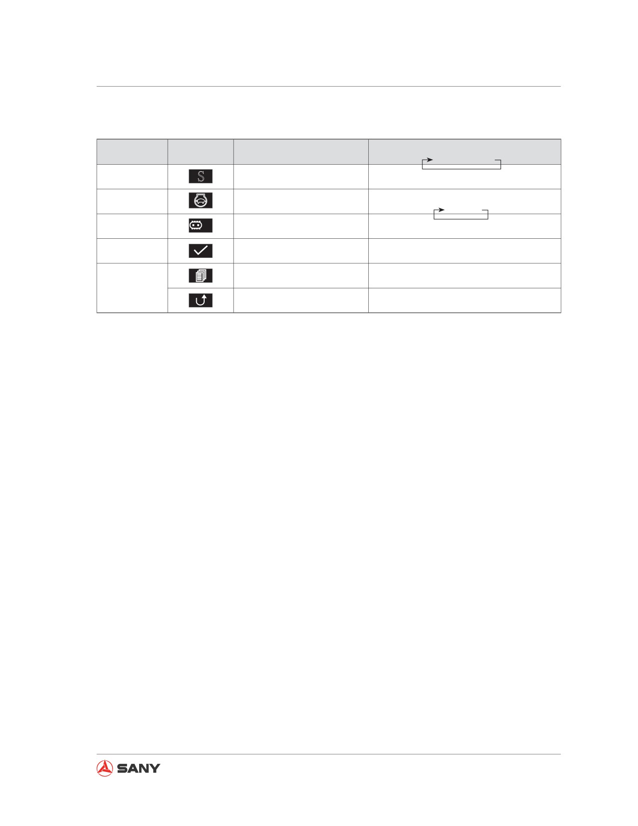
System Functions
Common icons and function keys
Function key
Icon
Function
Range
F1
S
Select a working mode
S→H→L→B
F2
Switch to idle/non-idle
Idle/non/idle
F3
Lo
Switch to high/low speed
Lo → Hi
F4
Access an option/setup
Same as the Enter key
View information
——
F5
Return to previous page
Same as the Esc key
Table 3-1
Default setup after starting the engine
● Working mode: S
● Full speed/auto idle: auto idle
● High/Low travel speed: low
Auto idle switch
● The auto idle switch is on as default. If no operation is performed within 5s, the engine will en-
ter auto idle (the controller changes engine speed to idle) in order to reduce fuel consumption
and noise.
● If the controller detects any operation or gear position change under idling state, the engine
will restore its original speed automatically.
● Auto idle function is disabled under L mode.
3-9
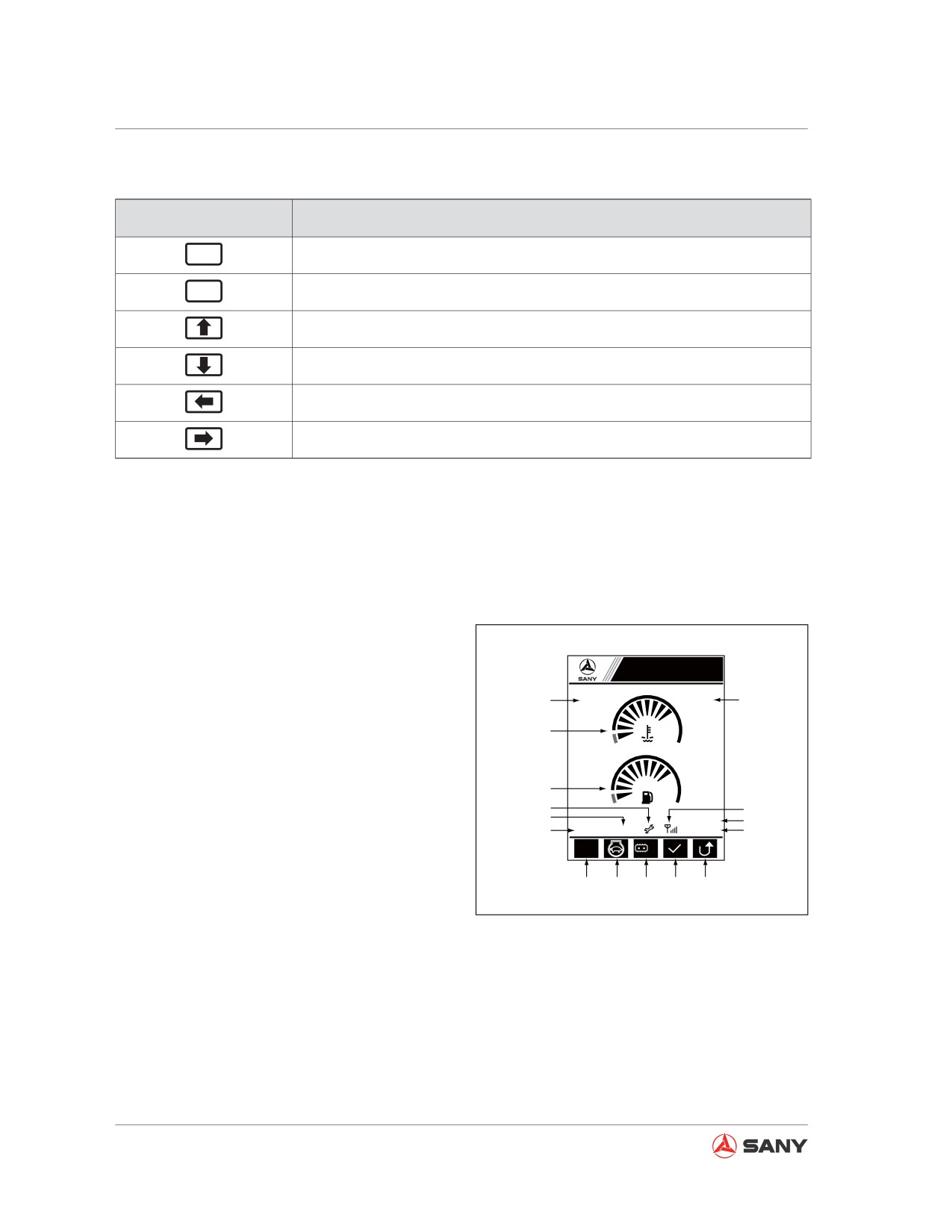
System Functions
2. Navigation keys
Navigation key
Function
Enter
Enter an option/setup item.
ESC
Return to previous page.
Select previous item (select the last item after the first one).
Select next item (select the first item after the last one).
Select the left item (select the right most item after the left most one).
Select the right most item (select the left most item after the right most one).
Table 3-2
3.3.2 System information and operation
3.3.2.1 Main Page
Normally, the monitor displays the working
mode, current date, throttle position, coolant
temperature, fuel level, operating hours, warn-
Sany Hydraulic Excavator
ing information, maintenance prompt, GPRS
1
S
1
15
signal, real time, etc. The user can set up the
operating conditions of the machine.
2
Screen output
3
1. Working mode (S, H, L or B)
9
10
7
09/03/05
14
4
0000h 00m
12
12:25:31
13
2. Coolant temperature (°C)
S
Lo
3. Fuel level (%)
5
6
8
11
12
4. Engine total operating hours (h/m)
XP1351106002
5. Press [F1] to select a working mode:
Fig. 3-7
S → H → L → B → S……
6. Press [F2] to switch on/off auto idle:
OFF → ON → OFF……
7. Failure code, if any, is refreshed every 2s.
8. Press [F3] to change travel speed:
Hi → Lo → Hi……
9. The icon appears if some maintenance is
3-10
System Functions
to be done.
10. GPRS signal.
11. Press [F4] to access failure codes.
12. Press [F5] to access “System
Information”.
13. System clock (h:m:s)
14. System calendar (Y/M/D)
15. Fuel control dial position (1-11)
Keypad input
[F1]: Select a working mode (S, H, L or B).
[F2]: Select auto idle or full speed.
[F3]: Select high/low travel speed.
[F4]: View "Failure Code".
[F5]: View "System Information".
[ Ĺ ]: Access "Service Call".
[ Ļ ]: View "Maintenance Information" if any
maintenance is to be done.
3-11
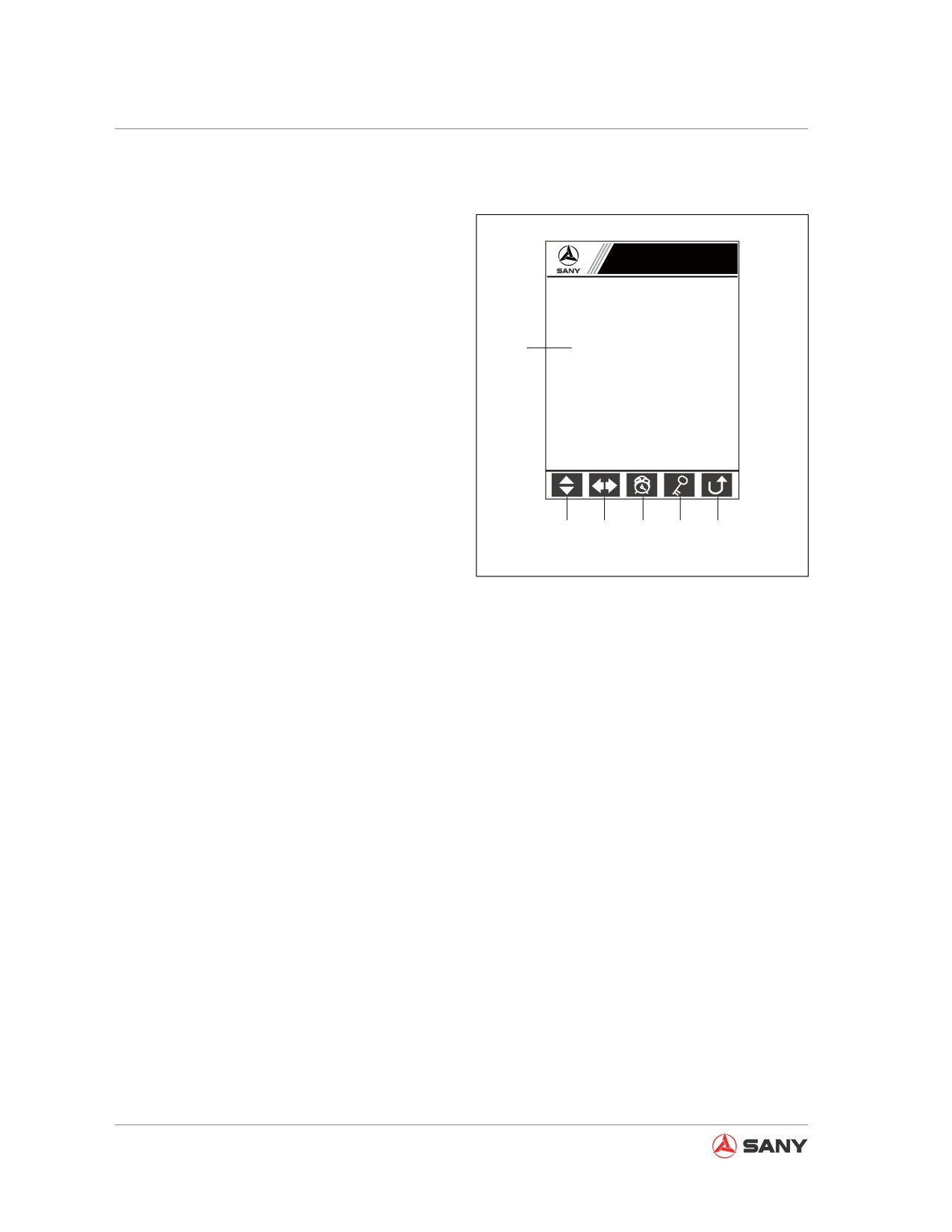
System Functions
3.3.2.2 System Information
Pass code is required to access system infor-
mation.
System Information
Screen output
Please enter the password:
1. A 5-digit pass code is required to access
system information, with each indicated by
1
̷Ḥ̷Ḥ̷Ḥ̷Ḥ̷
an asterisk (*) standing for a value from 0
to 9. A numeral appears at the digit where
the cursor is located while the other four
digits are in asterisk.
2. Press [F1 to increase/decrease the digit
value at where the cursor is located.
3. Press [F2] to move the cursor the left/right
digit.
2
3
4
5
6
4. System clock setup
XP1351106003
5. P r e s s
[F4] to access
“Unlock the
Fig. 3-8
System”.
6. Press [F5] to return to the “Main Page”.
Keypad input
[ ↑ ] [ ↓ ]: Increase/decrease the value at the
digit where the cursor is located.
[
← ] [ → ]: Move the cursor to the left/right
digit.
[F1]: Increase the value at where the cursor is
located.
[F2]: Move the cursor to the left/right digit.
[F3]: Access "System Clock Setup".
[F4]: Acdess "Unlock the System".
[F5]: Return to the "Main Page".
[ESC]: Return to the "Main Page".
[Enter]: Check the validity of pass code. If the
pass code is valid, you are allowed to access
the "Main Menu".
3-12
System Functions
3.3.2.3 Time Setup
Set up the time of system clock.
Time Setup
Screen output
1. Date and time.
Y/M/D
h/m/s TZ
2. Enter time setup.
1
2010 09 30 13 32 55 08 E
3. Return to "System Information".
Keypad input
[ ↑ ] [ ↓ ]: Increase/decrease the value by 1.
[ ← ] [ → ]: Move the cursor.
[F1]: Enter time setup
[F5]: Return to the "System Information".
2
3
XP1351106004
Fig. 3-9
3-13
System Functions
3.3.2.4 Main Menu
A list of system functions that can be selected
to access different options.
Main Menu
Screen output
Operating parameters
Machine configuration
1. Menu of system functions.
1
Failure codes
2. A short description of the item selected, in-
Maintenance Information
cluding: a) operating parameters of engine,
Engine speed calibration
main pump and main valve; b) Information
Language selection
of major components; c) Failure code and
GPS monitoring information
explanation; d) Maintenance information
Operating parameters of the engine,
of the engine, hydraulic system, etc.; e)
2
main pump and main valve.
Auto setup of fuel control dial positions (1-
11) and engine speed; f) System language
setup; g) GPS information.
3
4
5
6
3. Press [F1] to scroll through the “Main
XP1351106005
Menu”.
4. Press [F2] to access item selected.
Fig. 3-10
5. Press [F4] to access “System Setup”.
6. Press [F5] to return to the “Main Page”.
Keypad input
[ ↑ ] [ ↓ ]: Scroll through the "Main Menu".
[F2]: Access the item selected.
[F4]: Acdess "System Setup".
[F5]: Return to the "Main Page".
3-14
System Functions
3.3.2.5 Engine & Throttle Signals
Displaying operating parameters of engine.
Engine & Throttle Signals
Screen output
1. Real-time display of engine signals col-
Fuel level %:
68
lected by the controller.
Oil pressure kPa:
450
Hyd oil temp °C:
0
2. Press [F1] to view "Main Pump Signals" on
1
a positive flow machine.
Throttle gear N:
1
Engine speed rpm: 1000
3. Press [F5] to return to the "Main Menu".
Gear position V:
1.662
Throttle position V: 2.431
Keypad input
[F1]: View “Main Pump Signals” on a posi-
tive flow machine.
[F5]: Return to the "Main Menu".
2
3
[ESC]: Return to the "Main Page".
XP1351106006
Fig. 3-11
3.3.2.6 Main Pump Signals
Displaying parameters of the main pump.
Screen output
Main Pump Signals
1. Real-time display of main pump signals
Pump_1 main pressure %:
0
collected by the controller.
Pump_2 main pressure Kg:
0
2. Press [F1] to view "Input Switch Signals" .
Pump_1 negative pressure Kg:
0
1
Pump_2 negative pressure Kg:
0
3. Press [F5] to return to the "Main Menu".
Main pump back pressure Kg:
0
Proportional valve_1 current mA: 0
Keypad input
Proportional valve_2 current mA: 0
[F1]: View “Input Switch Signals”.
[F5]: Return to the "Main Menu".
[ESC]: Return to the "Main Menu".
2
3
XP1351106007
Fig. 3-12
3-15
System Functions
3.3.2.7 Input Switch Signals
Displaying input switch signals.
Input Switch Signals
Screen output
○ Start input
○ Boom UP
1. Real-time display of input switch signals.
1
○ Shutdown input
○ Boom DOWN
2. Press [F1] to view "Output Switch Signals".
○ Secondary boosting
○ Arm IN
3. Press [F5] to return to the "Main Menu".
○ Hydraulic pilot
○ Arm OUT
○ Air filter plugged
○ Bucket DIG
Keypad input
○ Water Separator
○ Bucket DUMP
○ Coolant temp high
○ Left swing
[F1]: View “Output Switch Signals”.
○ Travel indication
○ Right swing
[F5]: Return to the "Main Menu".
[ESC]: Return to the "Main Menu".
2
3
XP1351106008
Fig. 3-13
3.3.2.8 Output Switch Signals
Displaying output switch signals.
Output Switch Signals
Screen output
1
Start relay
○
1. Real-time display of output switch signals.
Preheat relay
○
2. Press [F1] to view "Engine & Throttle
Signals".
Shutdown relay
○
3. Press [F5] to return to the "Main Menu".
Secondary boosting valve
○
High-speed travel valve
○
Keypad input
Hydraulic pilot valve
○
[F1]: View “Engine & Throttle Signals”.
[F5]: Return to the "Main Menu".
[ESC]: Return to the "Main Menu".
2
3
XP1351106009
Fig. 3-14
3-16
System Functions
3.3.2.9 Machine Configuration
Displaying major components of the machine.
Machine Configuration
Screen output
1. Machine configuration information.
1
Machine model:
SY135C8B
2. Press [F5] to return to the "Main Menu".
Machine number:
018998
Engine number:
ISUZU_II
Keypad input
Hydraulic system:
KPM_N
[F5]: Return to the "Main Menu".
Control system: SYFCS
[ESC]: Return to the "Main Menu".
2
XP1351106010
Fig. 3-15
3.3.2.10 Failure codes
Displaying failure codes and explanation.
Failure Codes
Screen output
Failure code:
4
5
Number of failures: 1
4
01:HCU system alarm
1. All failure codes and corresponding infor-
02:TRU system alarm
1
03:Oil pressure low
mation.
04:Fuel level low
05:Coolant temperature high
2. Press [F1] to browse failure information.
06:Air filter plugged
07:Engine speed low
08:Engine speed high
3. Press [F5] to return to the "Main Page".
09:Supply voltage abnormal
10:Hydraulic oil temperature high
11:Water separator abnormal
4. Number of failures.
12:Motor working range improper
13:Motor motion paused
14:Potentiometer for motor setup
5. Failure code.
20:Front pump pressure abnormal
21:Rear pump pressure abnormal
Keypad input
[F1]: Browse failure information.
2
3
XP1351106011
[F5]: Return to the "Main Page".
Fig. 3-16
[ESC]: Return to the "Main Page".
3-17
System Functions
3.3.2.11 Maintenance Information
Every 50 service hours
Maintenance Information
Screen output
1
Every 50 Service Hours
1. Maintenance interval.
2
① Grease the swing bearing. Slowly
rotate the bearing as you grease it.
2. Maintenance items.
② Change engine oil and replace its
filter element (initial replacement).
3. Press [F1] to call “System Setup”. Enter
③ Drain sediment and water from the
the pass code and confirm that mainte-
fuel filter.
④ Check the connection between air
nance is done.
cleaner and intake tube.
4. Press [F4] to start/pause rolling mainte-
nance:
→
→
……
5. Press [F5] to return to the “Main Page”.
Keypad input
3
4
5
XP1351106012
[F1]: Maintenance is OK.
Fig. 3-17
[F4]: Start/Pause rolling maintenance informa-
tion.
[F5]: Return to the "Main Page".
[ESC]: Return to the "Main Page".
[Enter]: Maintenance is OK.
3-18