SANY Crawler Hydraulic Excavator SY115C9, SY135C8, SY135C9, SY155H. Safety, Operation and Manitenance Manual - page 1
SY115C9/135C/155H
Crawler Hydraulic Excavator
Operation and Maintenance Manual
WARNING
Read and follow the safety precautions and instructions in this manual and on the ma-
chine decals. Failure to do can cause serious injury, death or property damage. Keep this
manual with the machine for reading and future reference.
Table of Contents
Table of Contents
1 Introduction
1.1 Overview
1-3
1.2 Your Documentation Package
1-4
1.2.1 Recommendations on using the documentation
1-5
1.2.2 Documentation storage
1-5
1.2.3 Manual organization
1-5
1.2.3.1 Introduction
1-6
1.2.3.2 Safety
1-6
1.2.3.3 System functions
1-6
1.2.3.4 Operation
1-6
1.2.3.5 Maintenance
1-6
1.2.3.6 Troubleshooting
1-7
1.2.3.7 Specifications
1-7
1.2.3.8 Optional Equipment
1-7
1.2.4 Page numbers
1-7
1.3 Your Sany Machine
1-8
1.3.1 Machine applications
1-8
1.3.2 Machine directions
1-8
1.3.3 Breaking in a new machine
1-9
1.3.4 Machine information
1-9
1.3.4.1 Product identification plate
1-9
1.3.4.2 Engine identification plate
1-10
1.3.4.3 Right and left drive motors
1-11
1.3.4.4 Swing motor
1-11
1.3.4.5 Hydraulic pump
1-11
1.3.4.6 Chassis serial number
1-12
1.3.4.7 Machine monitor
1-12
1.4 Table for serial number and distributor information
1-13
1.5 Correction Request Form - Technical Publications
1-14
1.6 Contact Information
1-15
2 Safety
2.1 Safety Information
2-5
2.2 Safety Messages
2-7
I
Table of Contents
2.2.1 Hazard alert wording
2-8
2.2.2 Other alert wording
2-9
2.2.3 Safety decals
2-9
2.2.3.1 Textual safety decals
2-10
2.2.3.2 Graphical safety decals
2-10
2.2.3.3 Safety decal locations
2-11
2.3
General Precautions
2-19
2.3.1 Safety rules
2-19
2.3.2 Abnormalities
2-19
2.3.3 Personal protective equipment
2-19
2.3.4 Fire extinguisher and first aid kit
2-21
2.3.5 Safety equipment
2-21
2.3.6 Cleaning your machine
2-22
2.3.7 Keeping the cab clean
2-23
2.3.8 Engaging the hydraulic lockout control
2-23
2.3.9 Handholds and steps
2-24
2.3.10 Overhead work
2-25
2.3.11 No sitting on attachment
2-25
2.3.12 Articulated parts
2-25
2.3.13 Preventing burns
2-25
2.3.13.1 Hot coolant
2-25
2.3.13.2 Hot oil
2-26
2.3.14 Preventing fire and explosion
2-26
2.3.14.1 Fire caused by fuel or oils
2-26
2.3.14.2 Fire caused by flammable materials
2-27
2.3.14.3 Fire caused by electric lines
2-27
2.3.14.4 Fire caused by hydraulic lines
2-28
2.3.14.5 Fire caused by illumination equipment
2-28
2.3.14.6 Fire caused by heat shield
2-28
2.3.15 In the event of fire
2-28
2.3.16 Windshield cleaning detergent
2-29
2.3.17 Preventing ejection of part
2-29
2.3.18 Falling object protection
2-30
2.3.19 Attachment installation
2-30
2.3.20 Attachment combination
2-31
2.3.21 Cab windows glasses
2-31
II
Table of Contents
2.3.22 Unauthorized modification
2-31
2.3.23 Job site investigation
2-31
2.3.24 Operation on soft ground
2-32
2.3.25 Overhead power cables
2-33
2.3.26 Ensuring a good visibility
2-34
2.3.27 Ventilating enclosed area
2-35
2.3.28 Asbestos hazard
2-35
2.3.29 Alternate exit
2-36
2.4
Safe Operation Precautions
2-37
2.4.1 Safe starting
2-37
2.4.1.1 Safe mounting
2-37
2.4.1.2 Seat adjustment
2-38
2.4.1.3 Seat belt
2-38
2.4.1.4 Before starting the engine
2-38
2.4.1.5 Engine starting rules
2-39
2.4.1.6 Safe starting
2-39
2.4.1.7 Starting engine in cold season
2-40
2.4.1.8 Engine starting aid
2-40
2.4.1.9 After starting the engine
2-41
2.4.2 Operation
2-42
2.4.2.1 Inspection before operation
2-42
2.4.2.2 Prior-operation precautions
2-42
2.4.2.4 Travel directions
2-43
2.4.2.3 Rules for steering safety
2-43
2.4.2.5 Rules for traveling safety
2-45
2.4.2.6 Safe traveling
2-46
2.4.2.7 Operation on an incline
2-47
2.4.2.8 Operation in snowy weather
2-48
2.4.2.9 Restricted operations
2-48
2.4.3 Parking the machine
2-51
2.4.3.1 Select a parking place
2-51
2.4.3.2 Machine shutdown
2-51
2.4.4 Transportation
2-52
2.4.4.1 Loading and unloading the machine
2-52
2.4.4.2 Transporting the machine
2-53
2.4.5 Battery
2-54
III
Table of Contents
2.4.6 Lifting objects with the machine
2-56
2.5
Precautions for Maintenance
2-57
2.5.1 Prior-maintenance precautions
2-57
2.5.2 Select a working area
2-57
2.5.3 Preparing the machine
2-58
2.5.4 Preparing yourself
2-59
2.5.5 Lock-out and tag-out
2-60
2.5.6 Using proper tools
2-60
2.5.7 Maintenance with engine running
2-61
2.5.8 Working under the machine
2-61
2.5.9 Track maintenance
2-62
2.5.10 Track tension adjustment precautions
2-63
2.5.11 Recoil spring
2-63
2.5.12 Welding operation
2-64
2.5.13 High-pressure hoses
2-64
2.5.14 Pressurized fluid
2-65
2.5.15 Hot cooling system
2-66
2.5.16 Air-conditioning system
2-66
2.5.17 High voltage precautions
2-67
2.5.18 Accumulator
2-67
2.5.19 Avoiding fire and explosion
2-68
2.5.20 Regular replacement of safety-related parts
2-69
2.5.21 Maintenance operation
2-70
2.5.22 Proper disposal of wastes
2-71
3 System Functions
3.1 Machine Overview
3-5
3.2 Machine Controls
3-6
3.3 Monitor
3-7
3.3.1 Monitor introduction
3-7
3.3.2 System information and operation
3-10
3.3.2.1 Main Page
3-10
3.3.2.2 System Information
3-12
3.3.2.3 Time Setup
3-13
3.3.2.4 Main Menu
3-14
3.3.2.5 Engine & Throttle Signals
3-15
IV
Table of Contents
3.3.2.6 Main Pump Signals
3-15
3.3.2.7 Input Switch Signals
3-16
3.3.2.8 Output Switch Signals
3-16
3.3.2.9 Machine Configuration
3-17
3.3.2.10 Failure codes
3-17
3.3.2.11 Maintenance Information
3-18
3.3.2.12 Engine Speed Calibration
3-23
3.3.2.13 Language Selection
3-25
3.3.2.14 GPS Monitoring Information
3-26
3.3.2.15 System Setup
3-27
3.3.2.16 Machine configuration setup
3-28
3.3.2.17 Coolant Temperature
3-29
3.3.2.18 Service Call
3-30
3.4
Switches
3-31
3.4.2.1 Start switch
3-32
3.4.2.2 Fuel control dial
3-33
3.4.2.3 Work lamp switch
3-33
3.4.2.4 Wiper switch
3-35
3.4.2.5 Washer switch
3-36
3.4.2.6 Head lamp switch
3-36
3.4.2.7 Horn switch
3-37
3.4.2.8 Cab lamp
3-37
3.4.2.9 Cigar lighter
3-37
3.4.2.10 Preheat switch (only for SY135C8M)
3-38
3.4.2.11 Alternator indicator
3-38
3.5
Control levers and pedals
3-39
3.5.1 Hydraulic lockout control
3-40
3.5.2 Travel controls
3-41
3.5.3 Joystick controls
3-42
3.6
Roof Hatch
3-44
3.6.1 Opening the roof hatch
3-44
3.6.2 Closing the roof hatch
3-44
3.7
Windshield
3-45
3.7.1 Opening the window
3-45
3.7.2 Closing the window
3-48
3.7.3 Removing the lower window
3-50
V
Table of Contents
3.8 Alternate Exit
3-51
3.9 Door Catch
3-52
3.10 Cover/cap with a Latch
3-52
3.10.1 Opening/closing the cover with lock
3-53
3.10.2 Opening/closing the cap with lock
3-54
3.11 Cup Holder
3-55
3.12 Storage Box
3-56
3.13 Literature Bag
3-56
3.14 Ashtray
3-57
3.15 Air Conditioning System
3-58
3.15.1 Control panel
3-58
3.15.2 Operation method
3-64
3.15.3 A/C operation precautions
3-72
3.16 Radio
3-74
3.16.1 Control panel
3-74
3.16.2 Radio operation
3-76
3.17 Auxiliary Power Supply
3-80
3.18 Fuses
3-80
3.19 Fusible Link
3-81
3.20 Controller
3-82
3.21 Toolbox
3-82
3.22 Grease pump frame
3-82
3.23 Fire extinguisher
3-83
4 Operation
4.1 Before Starting the Engine
4-5
4.1.1 Routine checks
4-5
4.1.2 Checks before starting
4-7
4.1.2.1 Fuel tank - check/drain
4-7
4.1.2.2 Water separator - check/drain
4-7
4.1.2.3 Drain valve - regulate
4-8
4.1.2.4 Hydraulic oil - check/refill
4-9
4.1.2.5 Coolant - check/refill
4-10
4.1.2.6 Oil in engine oil pan - check/refill
4-11
4.1.2.7 Electric wires - check
4-12
4.1.2.8 Fuel tank - check/refuel
4-13
VI
Table of Contents
4.1.2.9 Work lamp switch - check
4-14
4.1.2.10 Horn - check
4-15
4.1.3 Adjustment before operation
4-15
4.1.3.1 Operator seat
4-15
4.1.3.2 Rear view mirrors
4-17
4.1.3.3 Seat belt
4-19
4.1.4 Before Starting the Engine
4-20
4.2
Engine Starting
4-22
4.2.1 Engine Preheating
4-25
4.2.2 Warm-up operation
4-26
4.2.3 Selecting a working mode
4-26
4.3
Engine Shutdown
4-27
4.4
Machine Operation
4-28
4.4.1 Before moving the machine
4-28
4.4.2 Moving the machine forward
4-29
4.4.3 Moving the machine backward
4-30
4.4.4 Parking the machine
4-31
4.5
Steering Operation
4-32
4.5.4.1 Steering with travel controls
4-32
4.5.4.2 Steering with machine stopped
4-32
4.5.4.3 Steering during traveling
4-33
4.5.4.4 Pivot turn
4-33
4.5.1 Swing operation
4-34
4.6
Work Equipment Control and Operation
4-35
4.7
Working mode
4-37
4.8
Restricted Operations
4-38
4.8.1 Operation with swinging force
4-38
4.8.2 Operation with traveling force
4-38
4.8.3 Operation when hydraulic cylinder reaches its stroke end
4-39
4.8.4 Operation with bucket landing force
4-39
4.8.5 Operation with machine weight
4-40
4.8.6 Hard rocky ground
4-40
4.8.7 Sudden shift of travel speed during fast traveling
4-41
4.9
General Operation
4-41
4.9.1 Traveling operation
4-41
4.9.2 High-speed travel
4-41
VII
Table of Contents
4.9.3 Permissible depth of water
4-42
4.10 Traveling on Slope
4-42
4.10.1 Traveling downhill
4-44
4.10.2 Engine stalls on an incline
4-44
4.10.3 Cab door on an incline
4-44
4.11 Removing Machine from Mud
4-44
4.11.1 One track trapped
4-44
4.11.2 Both tracks trapped
4-45
4.12 Recommended Applications
4-45
4.12.1 Backhoe operation
4-45
4.12.2 Trench work
4-46
4.12.3 Loading operation
4-46
4.13 Parking Operation
4-47
4.14 Checks after Each Workday
4-49
4.15 Locking the Machine
4-50
4.16 Operation in Cold Weather
4-50
4.16.1 Operation instruction
4-50
4.16.1.1 Fuel and lubricant
4-50
4.16.1.2 Battery
4-51
4.16.2 After each workday
4-52
4.16.3 After cold season
4-53
4.17 Long-Term Storage
4-54
4.17.1 Before storage
4-54
4.17.2 During storage
4-55
4.17.3 After storage
4-56
4.17.4 Starting the engine after long-term storage
4-56
4.18 Transportation Information
4-57
4.18.1 Transport methods
4-57
4.18.2 Loading/unloading machine to/from a trailer
4-57
4.18.2.1 Loading the machine
4-59
4.18.2.2 Securing the machine
4-61
4.18.2.3 Rear view mirrors
4-62
4.18.2.4 Unloading the machine
4-63
4.18.3 Lifting the machine or its components
4-65
4.18.3.1 Lifting precautions
4-65
4.18.3.2 Choosing a wire rope
4-66
VIII
Table of Contents
4.18.3.3 Lifting the machine
4-67
5 Maintenance
5.1 Maintenance Information
5-5
5.2 General Service
5-9
5.2.1 Oil, fuel and coolant
5-9
5.2.1.1 Oil
5-9
5.2.1.2 Fuel
5-10
5.2.1.3 Coolant
5-11
5.2.2 Grease
5-12
5.2.3 Oil and fuel storage
5-13
5.2.4 Filter element
5-13
5.2.5 Electrical system
5-14
5.2.6 Hydraulic system
5-14
5.3 Replacement Parts
5-16
5.4 Recommended Fluids
5-17
5.4.1 Fluid capacities
5-19
5.4.2 Recommended oils:
5-20
5.5 Tightening Torque Specification
5-22
5.6
Safety-Related Parts
5-24
5.7
Maintenance Schedule
5-25
5.7.1 List of maintenance schedule
5-25
5.7.2 Hydraulic Breaker Service Interval
5-27
5.8
Maintenance Procedures
5-28
5.8.1 Maintenance after initial 50 service hours
5-28
5.8.1.1 Engine oil and filter - change/replace
5-28
5.8.1.2 Fuel filter - replace
5-28
5.8.2 When Required
5-29
5.8.2.1 Air cleaner - clean/replace
5-29
5.8.2.2 Cooling system - clean
5-37
5.8.2.3 Track shoe bolts - inspect/tighten
5-41
5.8.2.4 Track tension - inspect/adjust
5-42
5.8.2.5 Bucket tips (lateral pin) - replace
5-45
5.8.2.6 Bucket Replacement
5-47
5.8.2.7 Bucket clearance - adjust
5-49
5.8.2.8 Window washer fluid - check/refill
5-51
IX
Table of Contents
5.8.2.9 Air conditioner - inspect/service
5-52
5.8.2.10 Gas spring - inspect
5-54
5.8.2.11 Air in hydraulic system - purge
5-55
5.8.2.12 Hydraulic circuit internal pressure - release
5-58
5.8.3 Checks before starting
5-59
5.8.4 Every 100 service hours
5-60
5.8.4.1 Lubrication
5-60
5.8.5 Every 250 service hours
5-63
5.8.5.1 Compressor belt tension - inspect/adjust
5-63
5.8.5.2 Oil in engine oil pan and oil filter - change/replace
5-65
5.8.5.3 Primary fuel filter - replace
5-67
5.8.5.4 Secondary fuel filter - replace
5-71
5.8.6 Every 500 service hours
5-74
5.8.6.1 Swing bearing - lubricate
5-74
5.8.6.2 Swing pinion gear grease - check/refill
5-75
5.8.6.3 Coolant tank and radiator fins - inspect/clean
5-76
5.8.6.4 Air conditioner filters - clean
5-77
5.8.6.5 Swing drive oil - check/refill
5-80
5.8.6.6 Final drive oil - check/fill
5-81
5.8.7 Every 1000 service hours
5-82
5.8.7.1 Hydraulic oil filter - replace
5-82
5.8.7.2 Swing drive oil - change
5-84
5.8.7.3 Engine exhaust pipe clamps - check
5-85
5.8.7.4 Fan belt tension - check/replace
5-85
5.8.7.5 Nitrogen pressure in accumulator (breaker) - check
5-85
5.8.8 Every 2000 service hours
5-86
5.8.8.1 Final drive oil - change
5-86
5.8.8.2 Hydraulic tank filter screen - clean
5-88
5.8.8.3 Nitrogen pressure in accumulator (control oil circuit) - check
5-89
5.8.8.4 Hydraulic circuit internal pressure - release
5-92
5.8.8.5 Oil in hydraulic tank - change
5-93
5.8.8.6 Alternator - inspect
5-95
5.8.8.7 Engine valve clearance - check/adjust
5-95
5.8.9 Every 4000 service hours
5-95
5.8.9.1 Coolant pump - inspect
5-95
5.8.9.2 Start motor - check
5-95
X
Table of Contents
5.8.9.3 Accumulator (control oil circuit) - replace
5-96
5.8.9.4 High-pressure tube clamps and rubber - check
5-97
5.8.9.5 Compressor working condition - inspect
5-97
5.8.10 Every 8000 service hours
5-98
5.8.10.1 High-pressure tube clamps - replace
5-98
5.8.11 Every 10000 service hours
5-98
6 Troubleshooting
6.1 Troubleshooting Preparation
6-3
6.1.1 Checks before troubleshooting
6-3
6.1.2 Troubleshooting procedure
6-4
6.1.3 Troubleshooting precautions
6-6
6.1.4 Electrical circuits troubleshooting precautions
6-9
6.1.5 Hydraulic components handling precautions
6-10
6.2 Pseudo Failures
6-12
6.3 Towing the Machine
6-13
6.4 Towing Hook for Light Loads
6-15
6.5 Severe Operating Conditions
6-15
6.6 Engine Failures
6-16
6.6.1 Engine troubleshooting table
6-16
6.6.2 Coolant temperature high
6-19
6.6.3 Engine oil pressure low
6-20
6.6.4 When fuel exhausts
6-22
6.6.5 When engine rotates reversely
6-24
6.7 Failures of the Electrical System
6-25
6.7.1 Electrical system troubleshooting table
6-25
6.7.2 Failure codes
6-28
6.8 Battery
6-30
6.8.1 Battery removal and installation
6-30
6.8.2 Battery charging
6-31
6.8.3 Jump-starting the engine
6-32
6.8.3.1 Connecting the jumper cables
6-33
6.8.3.2 Starting the engine
6-34
6.8.3.3 Disconnecting the jumper cables
6-34
6.9 Failures of the Hydraulic System
6-35
6.10 Other Common Failures
6-39
XI
Table of Contents
7 Specifications
7.1 Machine Dimensions
7-3
7.2 Working Ranges
7-4
8 Optional Equipment
8.1
General Safety
8-3
8.1.1 Selection precautions
8-3
8.1.2 Reading the instruction books
8-3
8.1.3 Removal and installation precautions
8-3
8.1.4 Operation precautions
8-4
8.2
Hydraulic Control Elements and Oil Circuit
8-6
8.2.1 Location of the components
8-6
8.2.1.1 Stop valve
8-6
8.2.1.2 Selector valve
8-7
8.2.1.3 Control pedal
8-7
8.2.2 Hydraulic circuit
8-8
8.2.2.1 Hydraulic circuit switching
8-8
8.2.2.2 Shifting to breaker / general optional equipment
8-8
8.2.2.3 Connecting hydraulic oil circuit
8-9
8.2.2.4 Hydraulic oil passage
8-10
8.2.3 Optional equipment removal and installation
8-11
8.2.3.1 Removal
8-11
8.2.3.2 Optional equipment installation
8-13
8.2.4 Hydraulic oil and hydraulic tank filter - change/replace
8-15
8.2.5 Long-term storage
8-16
8.2.6 Hydraulic specifications
8-16
8.3
Optional equipment Guide
8-17
8.3.1 Work equipment combination
8-17
8.3.2 Bucket tips selection
8-19
8.3.2.1 Rockwork bucket tips
8-19
8.3.2.2 Earthwork bucket tips
8-19
8.4
Recommended Operations
8-20
8.4.1 Hydraulic breaker
8-20
8.4.2 Hydraulic breaker operation
8-21
8.5
Restricted Operations
8-22
8.6
Hydraulic Breaker Lubrication
8-25
XII
Table of Contents
8.7 Quick Coupler and Control System
8-26
8.7.1 Quick coupler installation
8-26
8.7.2 Operating precautions
8-28
8.8 Refueling System
8-29
8.8.1 Introduction
8-29
8.8.2 Components
8-30
8.9 Central Lubrication System
8-31
8.9.1 Scheme and components
8-31
8.9.2 System working principle
8-33
8.9.3 Setting the lubrication time of electric grease pump
8-34
8.9.4 Technical description
8-35
8.9.5 Adding grease with electric pump
8-36
XIII
Table of Contents
XIV
Introduction
Introduction
1 Introduction
1.1 Overview
1-3
1.2 Your Documentation Package
1-4
1.2.1 Recommendations on using the documentation
1-5
1.2.2 Documentation storage
1-5
1.2.3 Manual organization
1-5
1.2.3.1 Introduction
1-6
1.2.3.2 Safety
1-6
1.2.3.3 System functions
1-6
1.2.3.4 Operation
1-6
1.2.3.5 Maintenance
1-6
1.2.3.6 Troubleshooting
1-7
1.2.3.7 Specifications
1-7
1.2.3.8 Optional Equipment
1-7
1.2.4 Page numbers
1-7
1.3 Your Sany Machine
1-8
1.3.1 Machine applications
1-8
1.3.2 Machine directions
1-8
1.3.3 Breaking in a new machine
1-9
1.3.4 Machine information
1-9
1.3.4.1 Product identification plate
1-9
1.3.4.2 Engine identification plate
1-10
1.3.4.3 Right and left drive motors
1-11
1.3.4.4 Swing motor
1-11
1.3.4.5 Hydraulic pump
1-11
1-1
Introduction
1.3.4.6 Chassis serial number
1-12
1.3.4.7 Machine monitor
1-12
1.4 Table for serial number and distributor information
1-13
1.5 Correction Request Form - Technical Publications
1-14
1.6 Contact Information
1-15
1-2
Introduction
1 INTRODUCTION
1.1 Overview
♦ Sany-built machines offer high-quality per-
formance and star-grade, after-sales ser-
vice.
♦ Sany-built machines are widely used
throughout the industry for various types of
applications.
♦ Sany is a leading manufacturer of con-
struction equipment worldwide.
This operator’s manual provides safety, opera-
tion, maintenance, troubleshooting and techni-
cal specifications. In order to properly use your
equipment, it is important to read this manual
carefully before beginning any operations.
Items addressed in this manual are designed
to help you:
● Understand the structure and performance
of your crawler hydraulic excavator.
Fig. 1-1
● Reduce improper operation and point out
possible hazardous situations.
● Increase equipment efficiency during op-
eration.
● Prolong the service life of equipment.
● Reduce maintenance costs.
Always keep this manual nearby and have all
personnel involved with any job-related proce-
dures read it periodically.
If you sell the machine, be sure to give this
manual to the new owner.
Continuing improvements in the design of this
machine can lead to changes in detail which
may not be covered in this manual. Always
consult your Sany distributor for the latest
available information or if you have questions
regarding information in this manual.
1-3
Introduction
1.2 Your Documentation Package
The documentation for this machine includes
the following items:
● Safety, Operation & Maintenance Manual
(SOMM) — This manual is in the operator
cab seat pocket.
● Parts Book — This publication consists of
parts lists and matching drawings for or-
dering spare parts as-needed. If it was not
already shipped with your machine, the
parts book for your machine is available
directly from Sany.
● CD
— A VCR on safety, operation and
maintenance of your excavator is delivered
with the machine.
CD system requirements
In order to use the Sany CD, be sure of the
following:
Hardware:
● Intel® Pentium II® running at 500 MHz or
above
● At least 128 MB RAM
● CD-ROM drive
● Minimum screen resolution of 800 x 600
pixels, high-color depth
Software:
● Windows 2000, XP, Vista and Windows 7
operating systems
● Internet Explorer 6.0 or later (pop-up block-
er disabled)
● Acrobat Reader 7.0 or later version
1-4
Introduction
1.2.1 Recommendations on using the
documentation
● This documentation applies only to this
machine and should not be used with any
other machines.
● To ensure that the documentation is always
complete and up to date:
● Keep all pages inside its binder (if shipped
loose leaf).
● Use the CD to print and replace any miss-
ing pages or those made unreadable due
to damage, grease, dirt, etc.
● Insert Sany replacement pages immedi-
ately into the appropriate book; destroy old
versions of those pages.
● Replace outdated CD’s with new ones;
destroy the old ones to prevent any confu-
sion in the future.
1.2.2 Documentation storage
Always keep the operator manual and load
charts with the machine in the operator cab.
The parts book is best left either shelved in
the workshop area or office. It should always
be available to the maintenance and service
personnel as required.
These can be printed out from the CD.
1.2.3 Manual organization
The operator’s manual is designed for use
and maintenance of this machine. Each sec-
tion of this manual provides information you
should be familiar with before operating this
machine. Keep this manual with the machine
for your reference at all times. Replace it im-
mediately if it is damaged or lost. Due to im-
provement and updating of products, some
information may differ from your machine. If
you have any questions on the machine, con-
1-5
Introduction
tact your Sany distributor before operating or
repairing the machine.
1.2.3.1 Introduction
This section provides an overview of what is
covered in the rest of this manual, including
machine label information and Sany contact
information.
1.2.3.2 Safety
This section covers basic safety information
relating to this equipment. Make sure you fully
understand all the precautions described in
this manual and the safety labels on the ma-
chine before operating or maintaining this ma-
chine. Failure to do so may result in serious
injury or death.
1.2.3.3 System functions
This section provides an overview of all the
controls, alerts and operating systems on the
machine. It is important to study and become
familiar with all systems before proceeding
with any operations.
1.2.3.4 Operation
This section provides some basic operating
procedures for this machine. Study and be-
come familiar with all operating procedures
before performing any job functions with the
machine.
1.2.3.5 Maintenance
This section provides all general maintenance
and repair procedures. (Detailed rebuild / re-
placement / repair information are covered in
a separate shop manual.) Study and become
familiar with all repair and maintenance proce-
1-6
Introduction
dures before performing any repair or mainte-
nance operations.
1.2.3.6 Troubleshooting
This section includes common malfunctions
and fault diagnostics procedures for this crawl-
er hydraulic excavator operating system. Basic
mechanical, hydraulic and electrical system
troubleshooting is included.
1.2.3.7 Specifications
This section provides general required ma-
chine information for this crawler hydraulic
excavator. Some information may vary due to
design changes.
1.2.3.8 Optional Equipment
This section provides information regarding
optional equipment for the excavator as autho-
rized by Sany. If you will be using any optional
equipment, it is important to read the instruc-
tion manual for the optional equipment and the
general information related to optional equip-
ment in this manual.
1.2.4 Page numbers
The pages in this manual are numbered as the
following:
3-20
Page 20 of Chapter 3
Chapter 3
1-7
Introduction
1.3 Your Sany Machine
1.3.1 Machine applications
Sany Hydraulic Excavators are designed for the following operations:
● Excavating
● Leveling
● Digging
● Loading
● Demolishing
1.3.2 Machine directions
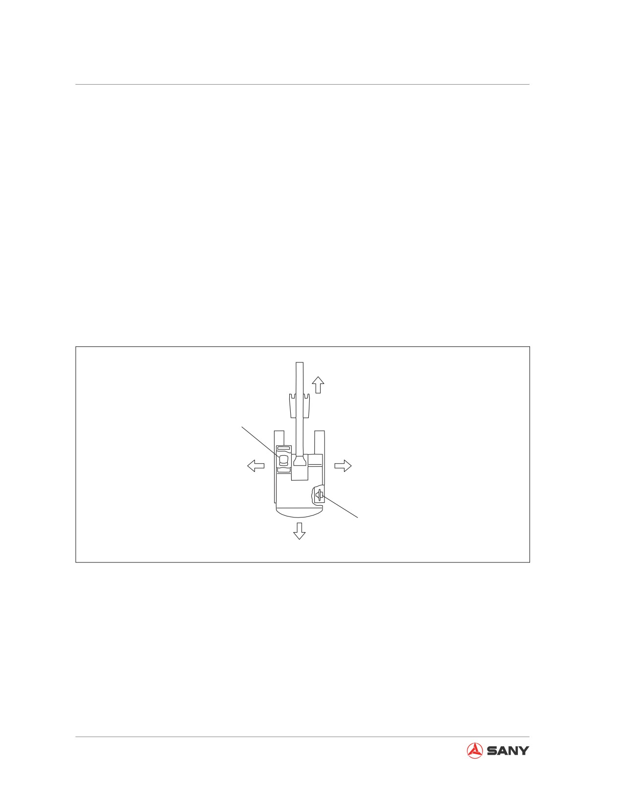
A
E
C
D
F
B
CZ335-1101001
Fig. 1-2
(A) Front
In this manual, the front, back, left or right di-
rection indicates, when the cab faces the front
(B) Back
and the final drive is behind of the machine,
(C) Left
the moving direction that you could see from
(D) Right
the cab.
(E) Operator Seat
(F) Sprocket
1-8
Introduction
1.3.3 Breaking in a new machine
Your machine has been thoroughly adjusted and tested before shipment. However, initial opera-
tion of the machine under severe conditions can adversely affect the performance of the machine
or shorten the machine life. Therefore, Sany recommends that you allow a break-in period of 100
operating hours for a new machine.
During the break-in period:
● Let the machine warm up before any operation.
● Avoid operating with severe loads or at high speeds.
● Avoid sudden starts or fast movements or stops.
● Always let the system cool down at the end of the working day.
1.3.4 Machine information
The serial numbers and model numbers on the components are the only numbers that your Sany
distributor will need when ordering replacement parts or requiring assistance for your equipment.
It is a good idea to record this information in this manual for future use. Below are the locations of
the data plates.
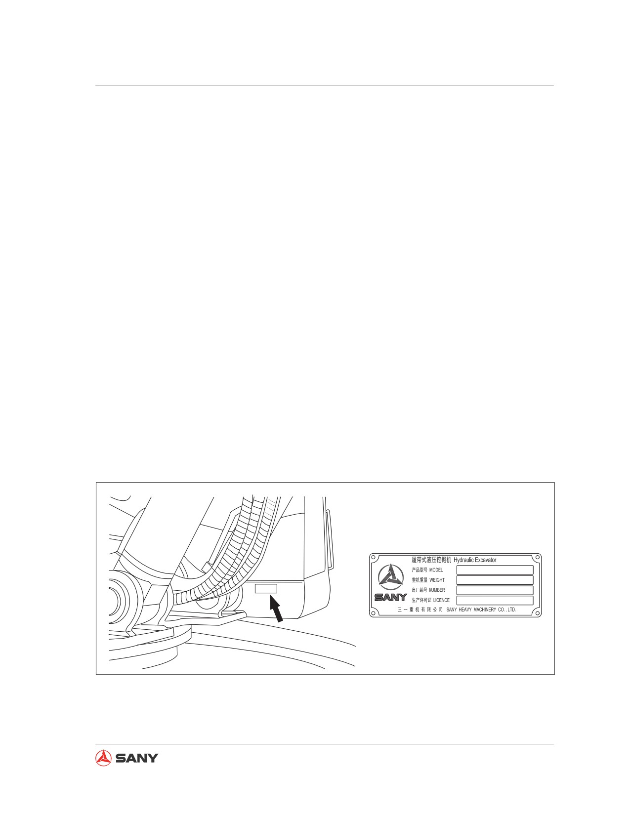
1.3.4.1 Product identification plate
On the right side of the operator station on the bottom.
CZ335-1101002
Fig. 1-3
1-9
Introduction
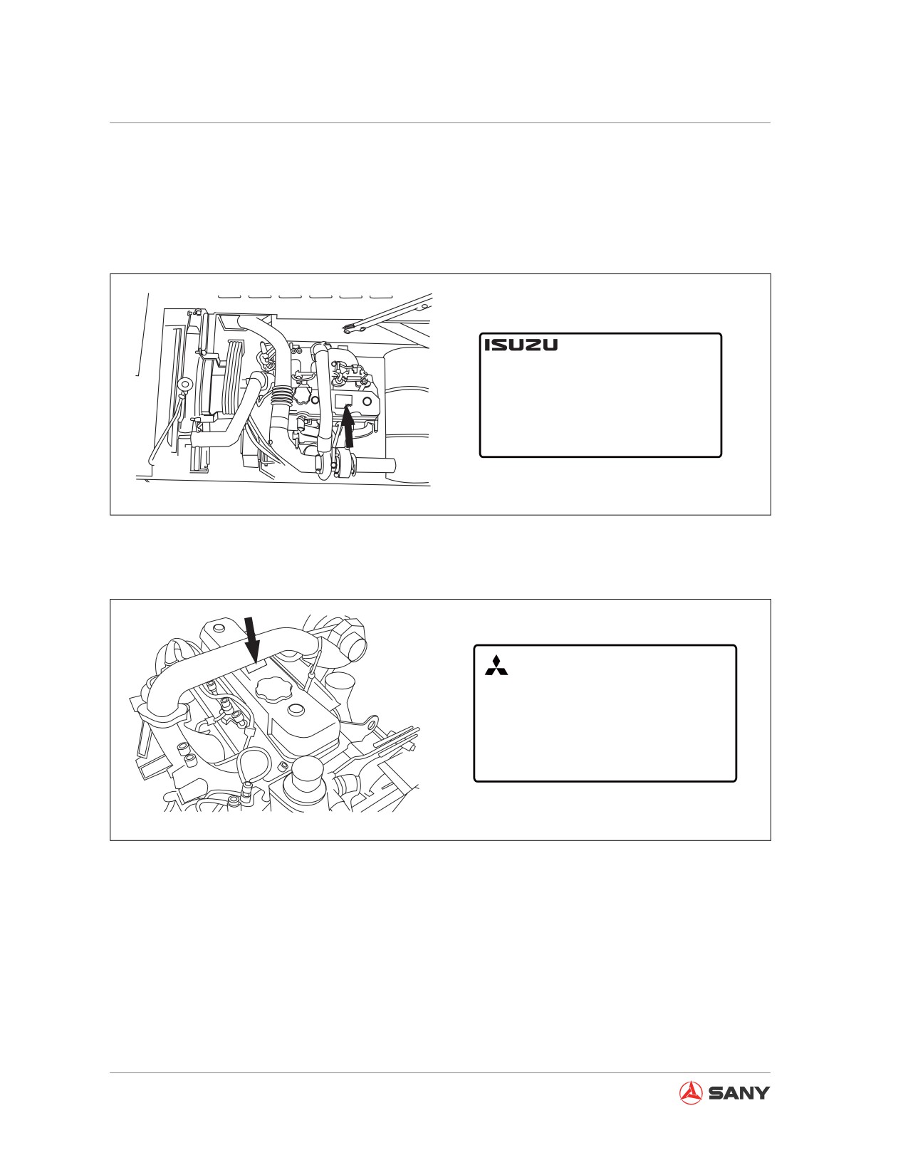
1.3.4.2 Engine identification plate
On cover of engine cylinder head.
SY115C9/SY135C8/SY135C9/SY155H
CONFORMED TO NATIONAL STAGE II NON-ROAD DIESL
ENGINE EMISSION CONTROL STANDARD
ENGINE FAMILY:
G20097L0433GTA
ENGINE MODEL:
4BG1-TABGC-03-C2
ENGINE POWER:
72.7 kW/ 2200 r/min
MANUFACTURER:
ISUZU
DATE OF MANUFACTURE:
POWER RANGE:
37 ≤ kW < 75
APPROVAL NO.:
CN FC G2 0097 21 0003
ENGINE CODE:
CZ155-1101001
Fig. 1-4
SY135C8(M)
MITSUBISHI FUSO
TRUCK & BUS CORPORATION
ENGINE FAMILY
ENGINE MODEL
4D34-TLU2B
APPROVAL NUMBER
ENGINE POWER 70kW-2050 r/min
THIS ENGINE CONFORMS TO CHINA NATIONAL STANDARD
GB20891-2007 STAGE II 37kW≤POWER<75kW
DATE OF MANUFACTURE: MONTH, YEAR
CZ155-1101002
Fig. 1-5
1-10
Introduction
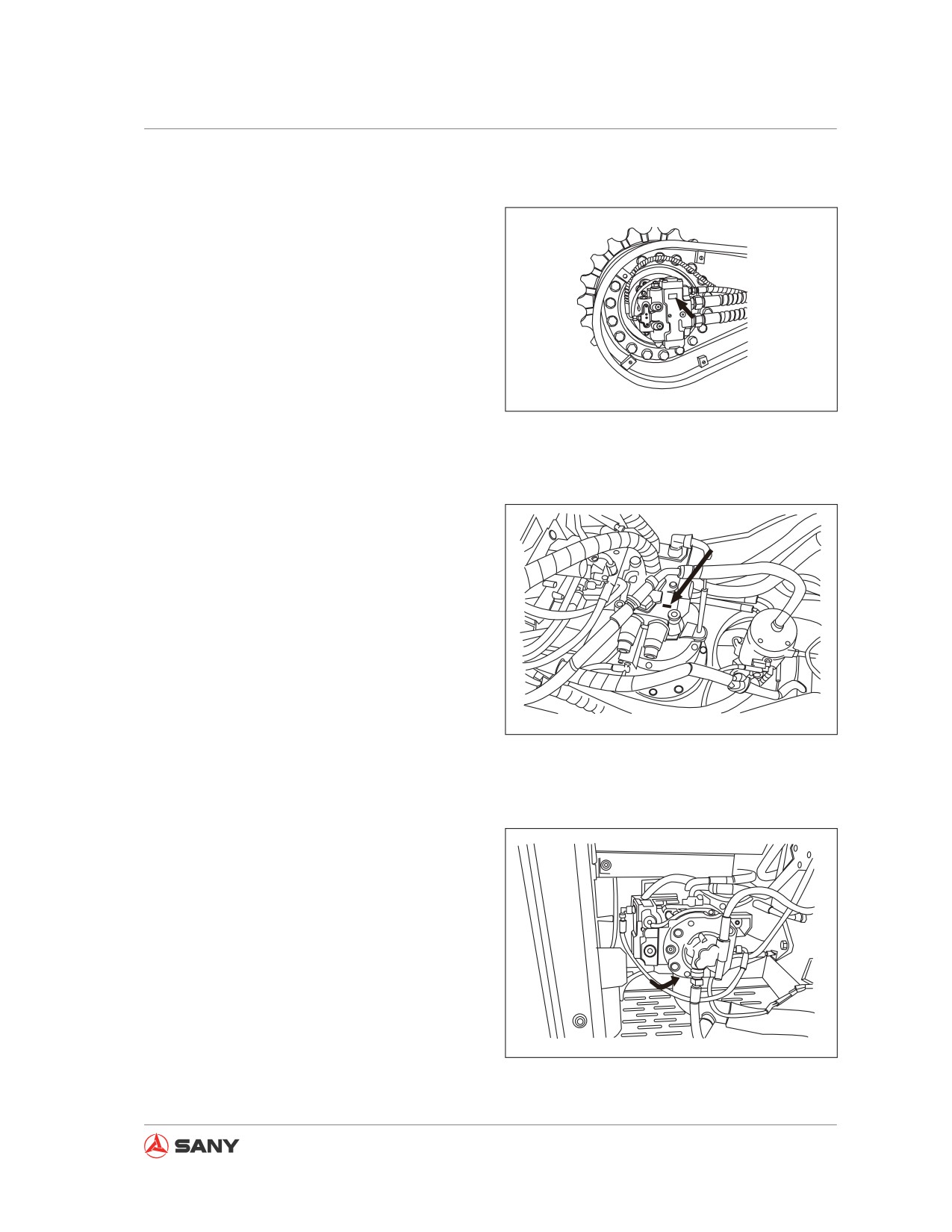
1.3.4.3 Right and left drive motors
On each drive motor:
Model: _____________________________
ID No.: _____________________________
CZ235-3100801
Fig. 1-6
1.3.4.4 Swing motor
On top of swing motor:
Model: ______________________________
ID No.: ______________________________
CZ235-3100802
Fig. 1-7
1.3.4.5 Hydraulic pump
On bottom of pump:
Model: ______________________________
ID No.: ______________________________
CZ235-3100803
Fig. 1-8
1-11
Introduction
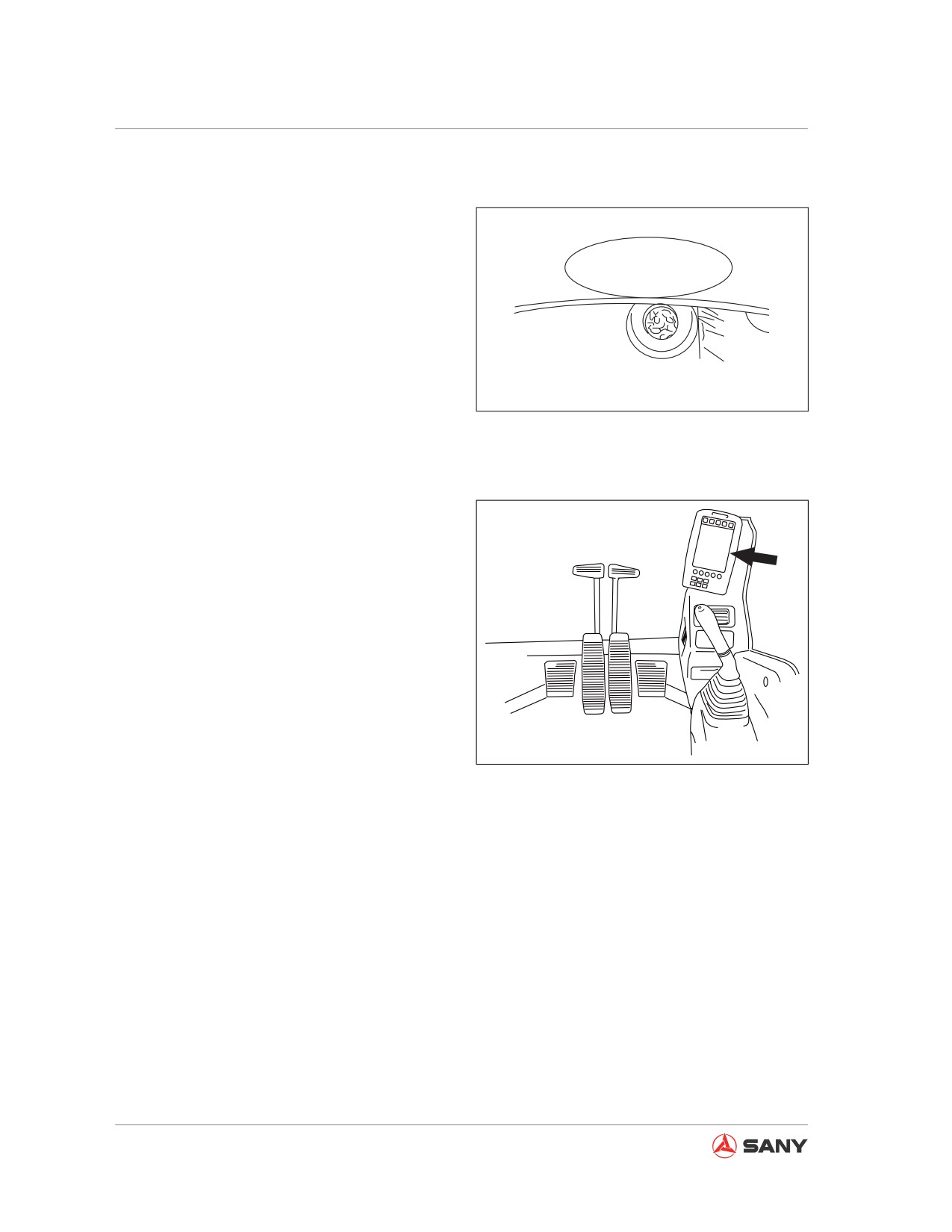
1.3.4.6 Chassis serial number
An additional serial number is stamped on the
front part of the travel carriage frame.
SYJ263038018060480
CZ235-3100804
Fig. 1-9
1.3.4.7 Machine monitor
Location of machine monitor is shown in the
right illustration.
CZ335-1101004
Fig. 1-10
1-12
Introduction
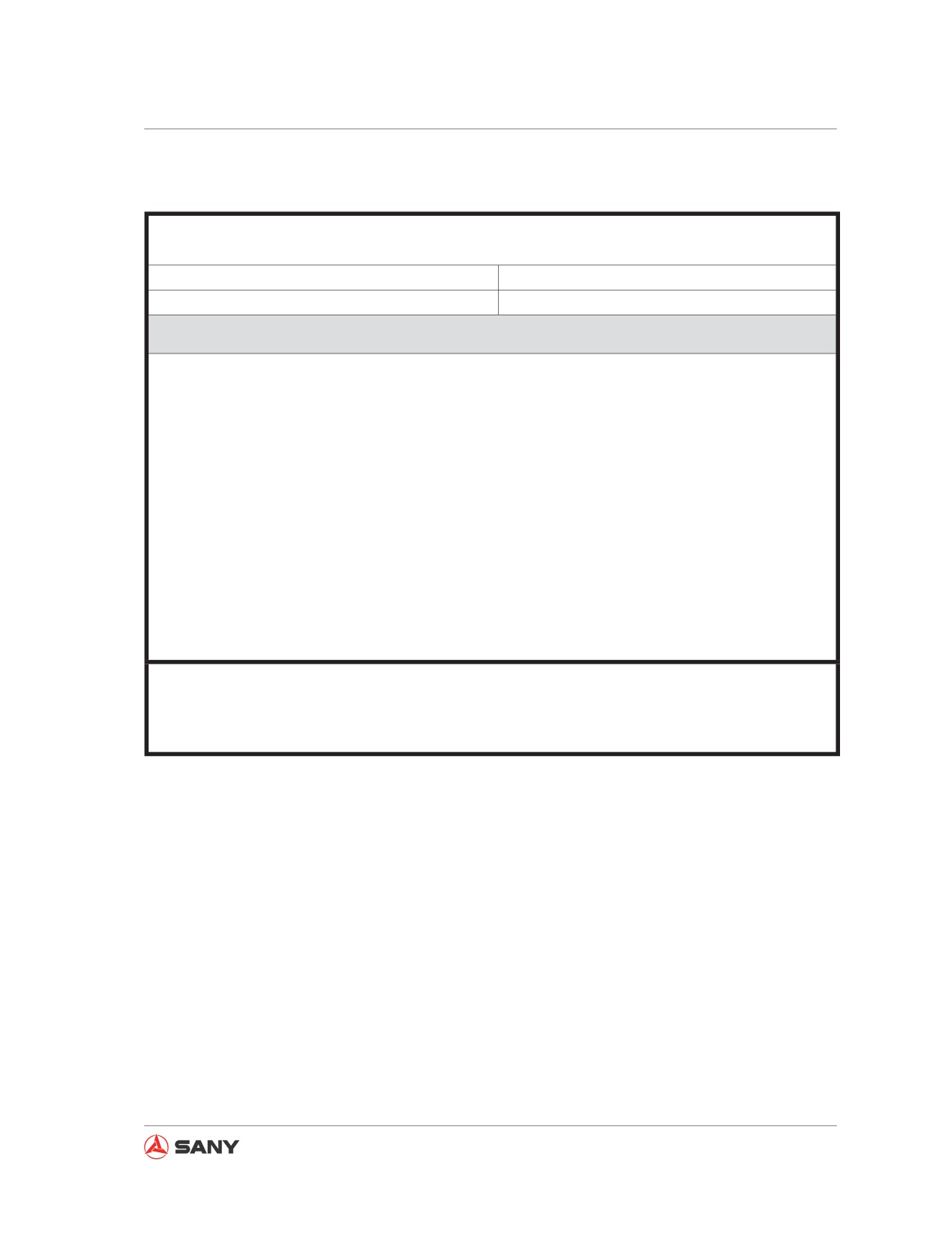
1.4 Table for serial number and distributor information
This location is for you to record information relating to your machine. It is advised that you keep
this manual with your machine at all times for reference.
Machine Serial No.
Engine Serial No.
Distributor Name:
Address:
Phone Numbers:
1-13
Introduction
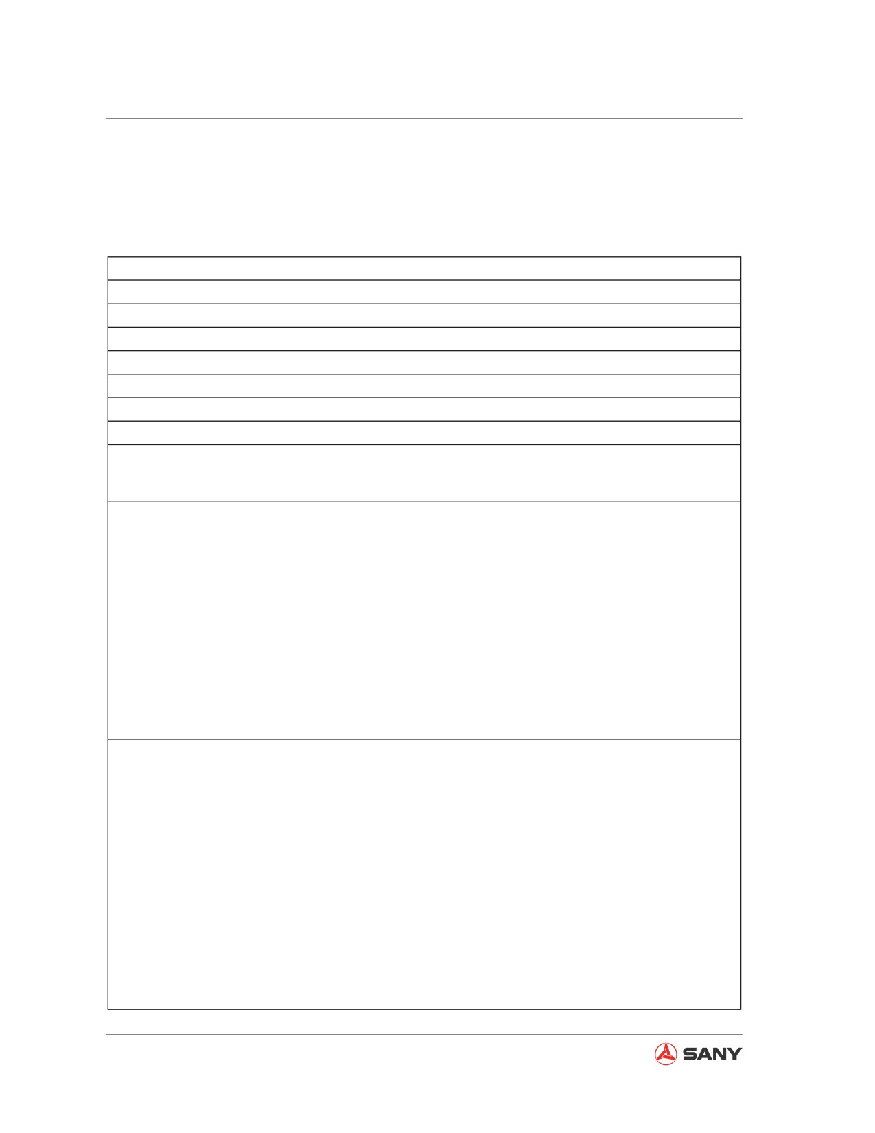
1.5 Correction Request Form - Technical Publications
If you find a problem with this manual, please make a copy of this page, fill out: the information
and send it to us attention Technical Publications. See Contact Information” on next page.
Date of this request
Your Name
Company Name
Your Department
Street Address
City, State & ZIP
Phone
E-mail
Machine Model & Serial No.
Description of Problem (Wrong information, unclear or erroneous procedure, etc.)
Corrective Action by You (if any)
1-14
Introduction
1.6 Contact Information
Thank you for purchasing a Sany machine. In the event that you should need to contact us for
any reason, you can reach us as follows:
Sany Heavy Machinery Limited
318A, Lianggang Avenue, Lingang Industrial Park, Fengxian District, Shanghai, P. R. of China
201413
Tel: (86) 21 5700 8518
Service hotline: (86) 4006 098 318
E-mail: crd@sany.com.cn
1-15
Safety
Safety
2 Safety
2.1
Safety Information
2-5
2.2
Safety Messages
2-7
2.2.1 Hazard alert wording
2-8
2.2.2 Other alert wording
2-9
2.2.3 Safety decals
2-9
2.2.3.1 Textual safety decals
2-10
2.2.3.2 Graphical safety decals
2-10
2.2.3.3 Safety decal locations
2-11
2.3
General Precautions
2-19
2.3.1 Safety rules
2-19
2.3.2 Abnormalities
2-19
2.3.3 Personal protective equipment
2-19
2.3.4 Fire extinguisher and first aid kit
2-21
2.3.5 Safety equipment
2-21
2.3.6 Cleaning your machine
2-22
2.3.7 Keeping the cab clean
2-23
2.3.8 Engaging the hydraulic lockout control
2-23
2.3.9 Handholds and steps
2-24
2.3.10 Overhead work
2-25
2.3.11 No sitting on attachment
2-25
2.3.12 Articulated parts
2-25
2.3.13 Preventing burns
2-25
2.3.13.1 Hot coolant
2-25
2.3.13.2 Hot oil
2-26
2-1
Safety
2.3.14 Preventing fire and explosion
2-26
2.3.14.1 Fire caused by fuel or oils
2-26
2.3.14.2 Fire caused by flammable materials
2-27
2.3.14.3 Fire caused by electric lines
2-27
2.3.14.4 Fire caused by hydraulic lines
2-28
2.3.14.5 Fire caused by illumination equipment
2-28
2.3.14.6 Fire caused by heat shield
2-28
2.3.15 In the event of fire
2-28
2.3.16 Windshield cleaning detergent
2-29
2.3.17 Preventing ejection of part
2-29
2.3.18 Falling object protection
2-30
2.3.19 Attachment installation
2-30
2.3.20 Attachment combination
2-31
2.3.21 Cab windows glasses
2-31
2.3.22 Unauthorized modification
2-31
2.3.23 Job site investigation
2-31
2.3.24 Operation on soft ground
2-32
2.3.25 Overhead power cables
2-33
2.3.26 Ensuring a good visibility
2-34
2.3.27 Ventilating enclosed area
2-35
2.3.28 Asbestos hazard
2-35
2.3.29 Alternate exit
2-36
2.4
Safe Operation Precautions
2-37
2.4.1 Safe starting
2-37
2.4.1.1 Safe mounting
2-37
2.4.1.2 Seat adjustment
2-38
2.4.1.3 Seat belt
2-38
2.4.1.4 Before starting the engine
2-38
2.4.1.5 Engine starting rules
2-39
2.4.1.6 Safe starting
2-39
2.4.1.7 Starting engine in cold season
2-40
2.4.1.8 Engine starting aid
2-40
2.4.1.9 After starting the engine
2-41
2.4.2 Operation
2-42
2.4.2.1 Inspection before operation
2-42
2.4.2.2 Prior-operation precautions
2-42
2-2
Safety
2.4.2.4 Travel directions
2-43
2.4.2.3 Rules for steering safety
2-43
2.4.2.5 Rules for traveling safety
2-45
2.4.2.6 Safe traveling
2-46
2.4.2.7 Operation on an incline
2-47
2.4.2.8 Operation in snowy weather
2-48
2.4.2.9 Restricted operations
2-48
2.4.3 Parking the machine
2-51
2.4.3.1 Select a parking place
2-51
2.4.3.2 Machine shutdown
2-51
2.4.4 Transportation
2-52
2.4.4.1 Loading and unloading the machine
2-52
2.4.4.2 Transporting the machine
2-53
2.4.5 Battery
2-54
2.4.6 Lifting objects with the machine
2-56
2.5
Precautions for Maintenance
2-57
2.5.1 Prior-maintenance precautions
2-57
2.5.2 Select a working area
2-57
2.5.3 Preparing the machine
2-58
2.5.4 Preparing yourself
2-59
2.5.5 Lock-out and tag-out
2-60
2.5.6 Using proper tools
2-60
2.5.7 Maintenance with engine running
2-61
2.5.8 Working under the machine
2-61
2.5.9 Track maintenance
2-62
2.5.10 Track tension adjustment precautions
2-63
2.5.11 Recoil spring
2-63
2.5.12 Welding operation
2-64
2.5.13 High-pressure hoses
2-64
2.5.14 Pressurized fluid
2-65
2.5.15 Hot cooling system
2-66
2.5.16 Air-conditioning system
2-66
2.5.17 High voltage precautions
2-67
2.5.18 Accumulator
2-67
2.5.19 Avoiding fire and explosion
2-68
2.5.20 Regular replacement of safety-related parts
2-69
2-3
Safety
2.5.21 Maintenance operation
2-70
2.5.22 Proper disposal of wastes
2-71
2-4
Safety
2 SAFETY
2.1 Safety Information
This Operation and Maintenance Manual is a
guide for you to operate your machine prop-
erly. It contains technical and safety informa-
tion necessary for operation of your machine.
Read and understand each section of the
manual.
Only eligible, experienced operators with an
official license (according to local laws) are al-
lowed to operate the machine.
Always operate your machine according to
national, provincial, prefectural and municipal
laws and regulations. The operation safety
information and description in this manual are
just suggestive and attentive.
Sany cannot anticipate every possible circum-
stance that might involve a potential hazard
during operation and maintenance. The Safety
messages in this manual and on the product
are, therefore, not all inclusive. If a procedure,
work method or operating technique that is not
specifically recommended in this manual is
used, you must be sure that it is safe for you
and for others. You should also ensure that
the product will not be damaged or be made
unsafe by the operation, lubrication, mainte-
nance or repair procedures that you choose.
Modifying or abusing the machine according
to your own will might impair the machine's
performance, or result in more serious poten-
tial hazard. For instance, the specific volume
of fuel exceeds set limit or the machine is
overloaded. Drive and operate the machine
carefully. Improper operation or application
may cause personal injury or machine dam-
age. Sany assumes no responsibility for such
losses.
2-5
Safety
Machines covered by this manual are used
for various operations under normal condi-
tions. Never use the machine in flammable or
explosive environment, or in areas containing
asbestos dust.
Select a Sany excavator that is suitable for
high-plateau operation when operating in
areas 2,000 m above the sea level.
This machine has gone through electromag-
netic capacity test according to EN 13309-
200C. All unapproved electronic attachments
(such as communication devices) are there-
fore to be tested before installation and ap-
plication. Make sure that the electromagnetic
attachments will not cause interference.
The information, specifications, and illustra-
tions in this publication are on the basis of
information that was available at the time that
the publication was written. Sany reserves the
right to change these information at any time
without prior notice. Consult your Sany dis-
tributor to obtain the latest information or if you
have any question on the information provided
in this manual.
Before starting operation and maintenance,
operator and service personnel shall observe
the following items:
● Read and understand the whole manual.
● Read and understand the safety notices
contained in this manual and the safety de-
cals on the machine.
● Never apply or operate your machine un-
der any circumstances that are prohibited
by the manual.
● If the amount of fuel added, content of par-
ticulates ,or latitude is beyond the speci-
fication of this type of machine, damage
could result and the warranty of your ma-
chine would become invalid.
2-6
Safety
The manual must be kept in the operator cab
for reference at any time.
If the book delivery with machine is missing or
cannot be read, contact your Sany distributor
to obtain a new one.
This manual should be regarded as a perma-
nent component of your machine. If the ma-
chine is sold to a third party, give this manual
to new owner.
The machine provided by Sany to its buyer is
in line with all specifications and standards of
buyer's country. If the machine is purchased
from another country or someone of a third
country, it might be lacking of some safety
devices or technical requirements necessary
for using the machine in your country. In case
you question whether the machine is in accor-
dance with the standards and specifications of
your country, you may contact local Sany dis-
tributor before operating the machine.
2.2 Safety Messages
Safety precautions given in this manual and
on machine decals, both textual and graphical,
provide information of hazardous situations
and methods to avoid such situations.
Before performing operation and maintenance
on the machine, the operator and after-sale
service personnel must understand all warn-
ing signs or symbols on the machine decals,
strictly follow the safety rules and precautions
specified in this manual, and take positive
actions so as to reduce the possibility of per-
sonal injury or death, the damage of machine
caused by improper service, and the risk of
unsafe factors, to the minimum.
2-7
Safety
2.2.1 Hazard alert wording
Hazard alert words are used in this manual
and on some machine decals to inform the
operator of imminent or potential hazards that
lead to death, personal injury or property dam-
age.
Different alert words are used to indicate the
degree of hazard.
It indicates an imminently
DANGER
hazardous situation which,
if not avoided, will result in
death or serious injury.
It indicates a potentially
WARNING
hazardous situation which,
if not avoided, could result
in death or serious injury.
It indicates a potentially
CAUTION
hazardous situation which,
if not avoided, may result
in minor or moderate in-
jury. It can also be used to
alert unsafe operation as
which may cause property
loss.
It indicates a situation
NOTICE
which can cause damage
to the machine, personal
property and/or the en-
vironment, or cause the
equipment to operate im-
properly.
This is the safety alert symbol. It is used
to alert you to potential personal injury
hazards. Obey all safety messages that
follow this symbol to avoid possible injury
or death.
2-8
Safety
An example alert wording and alert text
WARNING
● The hydraulic lockout control must be
placed in the LOCK position before you
leave the operator cab.
● An unlocked hydraulic lockout control
lever can cause serious injury or death
if maneuvered unexpectedly.
2.2.2 Other alert wording
In addition to the safety-related alert words
above, the following words are used in this
manual to provide additional information to
which extra attention must be paid.
Note:
It is followed by information on how to avoid
reduction of machine service life.
Remark:
It is followed by very useful information.
2.2.3 Safety decals
Safety decals on the machine are used to
alert operator or maintenance personnel that
potential hazards might be involved when the
machine is being operated or serviced.
We use textual and graphical (or combined)
decals to indicate a hazardous situation and
how to avoid such situation.
2-9
//////////////////////////////////////////