SANY Crawler Hydraulic Excavator SY215CLC (CUMMINS QSB6.7 engine). Shop Manual - page 36
 

  Index      Manuals     SANY Crawler Hydraulic Excavator SY215CLC (CUMMINS QSB6.7 engine). Shop Manual


Search            copyright infringement  


Content      ..     34      35      36      37     ..


SANY Crawler Hydraulic Excavator SY215CLC (CUMMINS QSB6.7 engine). Shop Manual - page 36


Disassembly and Assembly

SY215C

LC

8-84

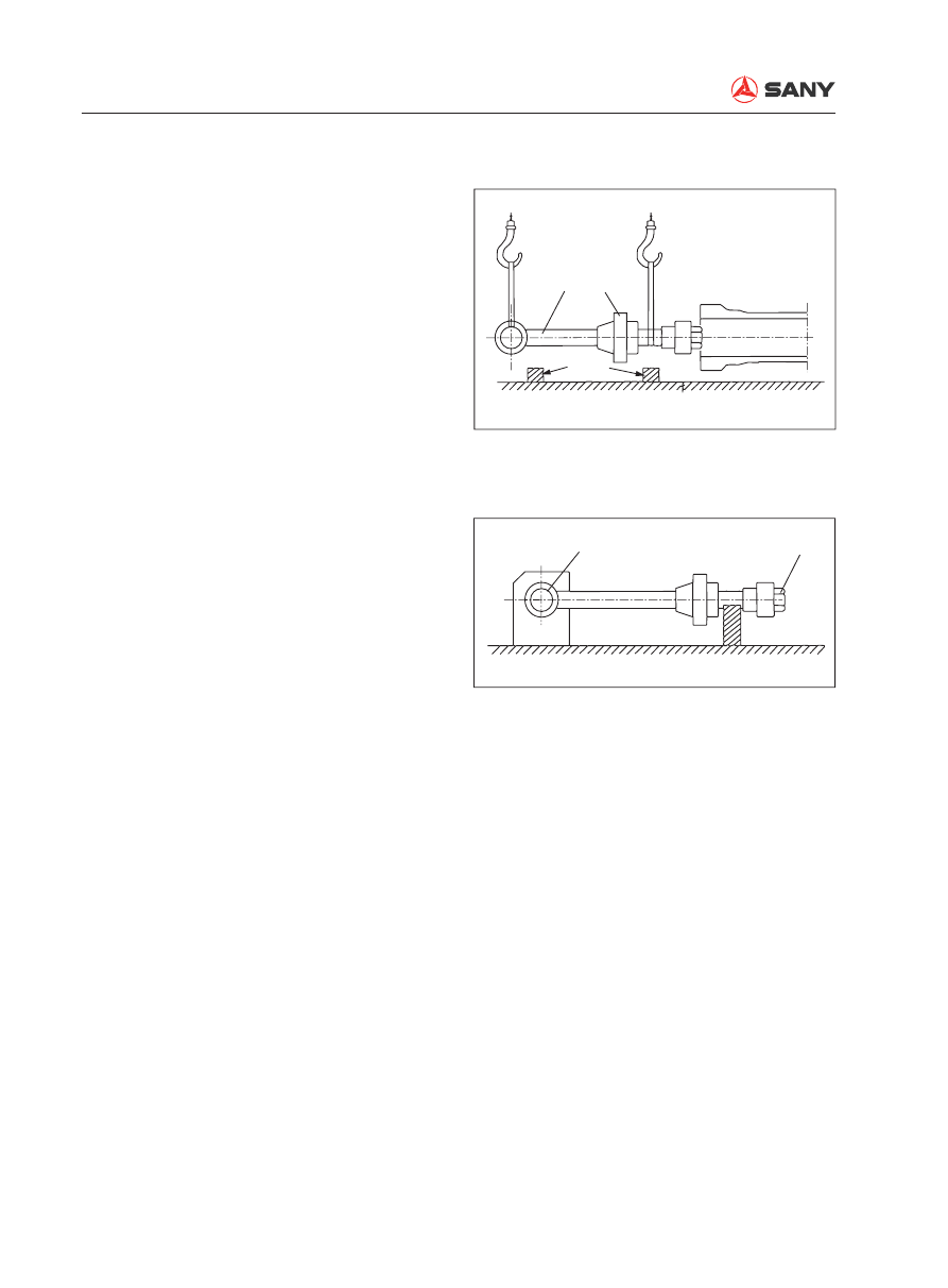
4.  Pulling out the piston rod


Be sure to have removed the tubing 
cover. 


Prepare a suitable container to collect 
oil coming out of the oil port.


After pulling out the piston rod to its 
limit, slowly loosen the cylinder head 
and pull it out. 


Remove the piston rod (1) with the 
cylinder head (2) and place them on a 
wooden sleeper. 

5.  Fixing the piston rod


Use pin bore on the rod end or the 

fl

 at 

part of the ear to prevent turning of the 
piston rod. 

1

2

Sleeper

ZX215-1006166

Fixing

5

ZX215-1006167

Disassembly and Assembly

SY215C

LC

8-85

7.  Removal of piston assembly

Remove in turn the piston (7), buffer sleeve 
(6) and cylinder head (2). 

6.  Remove of the piston nut (5)

1)  Remove the fixing screw (3) from the 

piston nut (5). 


Around the fixing screw there are two 
points that have been punched against 
loosening. After removing the riveted 
part with a hand drill, loosen and 
remove the 

fi

 xing screw (3). 

2)  Remove the steel ball (4).

3)  Remove the piston nut (5). 


The piston nut (5) is very tight. To 
loosen the piston nut (5), prepare a 
hydraulic jack or a spanner powered 
by hydraulic cylinder. An extension rod 
should be ready when removing the 
piston nut (5) manually. 

3

Drill bit

4

ZX215-1006168

5

Hydraulic jack

Hydraulic cylinder

ZX215-1006169

6

7

2

ZX215-1006170

Disassembly and Assembly

SY215C

LC

8-86

8.  Removal of the buffer sleeve (8) on the 

bottom end

1) Remove 

fi

 rst the piston nut (5). 

2)  Use a tool like rubber hammer to tap 

the piston nut (5) slightly for removal 
while keeping the piston rod and the 
buffer sleeve (8) intact. Remove the 
elastic ring (9). 

3)  Slide the buffer sleeve (8) toward the 

piston threads in order to remove the 
two-piece stopper ring.

4)  Remove the buffer sleeve (8). 

5)  There is an opening in the buffer seal 

(10). Take advantage of this opening to 
remove the buffer seal (10). 

9.  Removal of piston seal

1)  The slide ring (12) and the guard 

ring (13) can be simply removed with 
hands. 

2)  The seal (14) can be removed with a 

hammer and a 

fl

 at-head screwdriver. 

3)  Remove the O-ring seal (15) with a pry 

bar. 


The removed seals should not be 
reused. 

10.  Removal of buffer ring (16)


The buffer ring (16) is installed in the 
inner groove in the cylinder head. Use 
a tool with sharp end to pry it out and 
remove it with a scraper. 

Thread

Piston rod

9

10

one gap

8

11

(2 pcs)

ZX215-1006171

Bench clamp

Piston

Screwdriver

14

12

15

13

ZX215-1006172

18

19

17

16

20

ZX215-1006173

Disassembly and Assembly

SY215C

LC

8-87

11.  Removal of the U-ring (17) and the dust 

ring (18)

1)  Remove the U-ring (17) with a tool such 

as screwdriver. 

2)  Pierce a tool (such as a screwdriver) 

into the dust ring (18) and hammer the 
screwdriver to remove the dust ring 
(18). 


The removed seals should not be 
reused. 

12.  Removal of bushing (19)

1)  Remove the elastic ring (20) from the 

cylinder head (2) with a screwdriver. 

2)  Push the bushing (19) out with the help 

of clamps and press. 

13.  Removal of bushing (21)

1)  Remove the dust ring (22) on the side 

of cylinder barrel and piston rod with a 
tool such as screwdriver. 

2)  Remove the bushing (21) with the help 

of a suitable cushion block. 

Press

Cushion

Support

21

ZX215-1006174

Disassembly and Assembly

SY215C

LC

8-88

8.22.2 Assembly

1.  Installation of bushing (21)

1)  Use a mounting tool to press the bush-

ing (21) into the bushing (lubricated 
with hydraulic oil) on the side of piston 
rod and cylinder barrel. 

2)  Install the dust ring (22) with the help of 

a suitable cushion block. 

2.  Assembly of cylinder head (2)

1)  Use the press to push in the bushing 

(19). 


Apply hydraulic oil to the inside of  
cylinder head in advance. Make sure 
that the bushing (19) pushed in is free 
from a raised shoulder. 

2)  Use the press to push in dust ring (18). 

3)  Install the guard ring and the U-ring (17) 

sequentially in the U-groove. 


Install the U-ring (17) in correct direc-
tion. Make sure that the U-ring is intact 
before installation. 


Inverse installation will cause leak of 
oil. 


Make sure that the U-ring is free from 
any corrugation or permanent deforma-
tion after installation.

Piston rod

Cushion

22

21

Press

Mounting tool

21

ZX215-1006175

2

Surface
under pressure

Hydraulic press

Tool

19

ZX215-1006176

Press in

Tool

18

U-groove

ZX215-1006177

Disassembly and Assembly

SY215C

LC

8-89

4)  Installation of buffer ring (16)


Make sure that the seal is installed in 
correct direction. Inverse installation 
can cause high pressure between the 
buffer ring (16) and the U-ring (17), 
which may lead to deformation or 
breakage of oil cylinder. 

5)  Install the elastic ring (20) to prevent 

the fall of the bushing (19). 

3.  Assembling the piston assembly

1)  Installation of seal (14). 


Install 

fi

 rst the O-ring seal and the one-

side guard ring (13) on the piston. 
Place the piston on the press. As 
shown in the illustration on the right, 
the seal (14) is installed with the tools 
indicated. 

2)  Correction of seal (14)


Install the seal (14) and the guard 
ring (13) on the other side. In order to 
prevent the expansion of the seal (14), 
a corrector must be used to correct the 
seal (14) which has been stretched 
during installation. The piston rod may 
not be able to go in the cylinder barrel if 
the seal (14) is not corrected timely. 

3)  Installation of slide ring (12)


Slightly open the slide ring (12) and 
install it axially. Excessive opening of 
the slide ring (12) can fail installation.

18

19

17

16

20

ZX215-1006178

Press

Tool

Block

Press

13

Corrector

Piston

Tool

14

13

O-ring

12

ZX215-1006179

Disassembly and Assembly

SY215C

LC

8-90

4.  Assembling the piston rod assembly

1)  Fix the piston rod (1). 

2)  Install the cylinder (2) on the piston rod. 


Make sure that the dust ring lip or the 
U-ring lip is not stopped by the shoulder 
of any part. Install the cylinder head 
and the piston rod with the tools. 

3)  If the bottom side of cylinder contains 

a buffer (not for bucket cylinder), install 
the buffer bearing and the buffer seal in 
the following order. 

i)  Let the notched side of the buffer 

seal (10) face the piston while in-
stalling the buffer seal (10) in the 
groove. 

ii)  Install the buffer sleeve (8) accord-

ing to the indication in the illustra-
tion on the right. 

iii)  Install the stopper ring in the 

groove. Install the elastic ring af-
ter the buffer sleeve (8) is pushed 
to the bottom. A rubber hammer 
should be used for the tapping job 
in order to avoid damaging the pis-
ton rod and the buffer bearing. 

Assembly tool

2

1

ZX215-1006180

Gap facing thread direction

Thread

Piston rod

One gap

9

10

8

11

(2 pcs)

Head end buffer

ZX215-1006181

Disassembly and Assembly

SY215C

LC

8-91

6

5

23

Gap facing piston side

Rod end buffer

ZX215-1006182

4)  If the head side of cylinder contains a 

buffer, install the buffer sleeve (6) and 
the buffer seal (23) according to the fol-
lowing order. 

i)  The piston nut must be installed af-

ter installation of the buffer bearing. 

ii)  The buffer seal (23) must be in-

stalled in the groove, with its notch-
es facing the piston. 

iii)  The buffer sleeve (6) must be in-

stalled according to the illustration 
on the right. 

5)  Tighten the piston nut (5). 

 Piston nut (arm):

9600 N·m {979.6 kgf·m}

 Piston nut (boom and bucket):

6200 N·m {632.6 kgf·m}


Insufficient tightening can cause oil 
leakage, loose nut and thread break-
age. In addition, excessive tightening 
can cause expansion of the buffer shaft 
on the extending side or deformation of 
piston on the contact side. 


Thoroughly clean and grease (with 
banana oil) the threaded portions of 
the piston, nuts and piston rod before 
tightening the nuts. 

6)  Treatment of the piston against loosen-

ing

Disassembly and Assembly

SY215C

LC

8-92


After the piston nut (5) is tightened, 
put in the steel ball (4), tighten the 
setscrew (3) and punch to rivet the two 
peripheral points. 

 Setscrew (3): 

66.9 N·m {6.8 kgf·m}

5.  Install the piston into the cylinder barrel

1)  Fix the barrel in a vertical or level man-

ner. 

2)  Install the piston rod into the cylinder 

barrel. 


If 

fi

 xed in a vertical manner, the piston 

rod falls into the barrel under its gravity.


Make sure that the slide ring does not 
fall while the piston is inserted into the 
barrel. 

6.  Tightening of cylinder head 

Tighten the cylinder head according to the 

Rivet

Punch

3

4

ZX215-1006183

Tool
Nylon sleeve
(2 pcs type)

(Spread the
gaps by 180°)

ZX215-1006184

Disassembly and Assembly

SY215C

LC

8-93

sequence shown in the illustration on the 
right. 

 Bolt: 267 N·m {27.2 kgf·m}

7.  Install the tubing. 

Tightening sequence

8

4

12

6

10

2

1

9

5

11

3

7

ZX215-1006185

Disassembly and Assembly

SY215C

LC

8-94

8.23  

Work Equipment AS - Remove and Install

8.23.1 Removal

 Fully extend the arm and the bucket. 

Lower the work equipment to the ground. 
Move the hydraulic lockout control to the 
LOCK position. 

 Release residual pressure in the hydrau-

lic circuit. See “Residual Pressure in Hy-
draulic Circuit - Release” on page 6-29.

1.  Disconnect the grease hose (1). 

2.  Lift the boom cylinder assembly (2). 

Remove the lock bolt (3). 

3.  Remove the plate (4) and then the pin 

(5).      


There are shims installed. Count the 
shims and check the thickness. Place 
the shims in a safe place. 

4.  Start the engine and retract the piston 

rod.


Secure the piston rod with a wire rope 
in order to prevent the piston from 
slipping out. Place the cylinder on a 
bench or support. The grease 

fi

 tting on 

the bottom side must be removed in the 
later case. 


Remove the other boom cylinder in the 
same way. 

5.  Remove the two hoses (6) of bucket 

cylinder and the two hoses (7) of the arm 
cylinder. 


Cork the hoses to prevent out

fl

 ow of oil. 

Secure the hoses to the side of valve. 

1

2

3

4

5

ZX215T-1006186

ZXT225-1106028

6

8

7

9

10

Disassembly and Assembly

SY215C

LC

8-95

6.  Remove the inter-connector (8) used for 

work lamp. 

7.  Lift the work equipment and remove the 

plate (9). Remove the pin (10) from the 
bottom.


There are shims installed. Count the 
shims and mark their locations. 

8.  Lift and disassemble the work equipment 

assembly. 

  Work equipment assembly:  

3578 kg

9

10

ZX215T-1006188

11

ZX215T-1006189

Disassembly and Assembly

SY215C

LC

8-96

8.23.2 Installation


Installation is to be performed in the re-
verse order of removal. 


A clearance (a: 0.5 - 1.5 mm) should be 
left between the plate and the nut when 
tightening the locknut. 

 Greasing after assembling the 

pin: 

Grease (supramoly lithium base)

 Do not put your 

fi

 nger in the pin bore 

while aligning the pin bore. 


Adjust the shim thickness in order to have 
a desired clearance (a: 0.5<a<1 mm) 
between the piston end (12) and the plate 
(4). 


Standard shim thickness: 1.0 mm and 
2.0 mm. 


 Greasing after assembling the 

pin: 

Grease (supramoly lithium base)

 Do not put your 

fi

 nger in the pin bore 

while aligning the pin bore. 


Hydraulic oil adding

Add hydraulic oil to the specified level. 
Start the engine to circulate the oil in the 
hydraulic system, and check the oil level 
again. Add more hydraulic oil if necessary. 


Air bleeding

Bleed the air from travel motor. 

For more information, see “Air in Each 
Component - Bleed” on page 6-35. 

a

ZX215-1006190

a

4

12

ZX215-1006191

Disassembly and Assembly

SY215C

LC

8-97

8.24  Air Conditioner AS - Remove and Install

8.24.1 Removal

 Disconnect the cable from the negative (-) 

post of the battery. 

1.  Drain the coolant.     

 Coolant: approx. 22.5 L

2.  R e c o v e r   r e f r i g e r a n t   f r o m   t h e   a i r -

conditioning system with the tool (S).

3.  Remove the pad (1) on the cab 

fl

 oor. 

S

ZX215T-1006192

1

ZX215T-1006193

Special tools

ID

Part Name

Model

Necessity Qty

S

Refrigerant 

charger

Robinair

34711-2K

1

Refrigerant 

charger

Inoue Qing-

Hua

1

Disassembly and Assembly

SY215C

LC

8-98

5.  Remove the fuse box (3) and storage 

box (4). 

6.  Remove outer covering (5).

7.  Remove the air conditioner cover (6). 

4.  Open the left rear cover of the cab with 

the ignition key. Remove the outer filter 
element (2).

8.  Remove the back air duct (7). 

9.  Remove the left air duct (8). 

10.  Remove the baf

fl

 e (9). 

11.  Remove the right air duct (10). 

ZX215T-1006196

3

6

4

5

7

8

9

10

ZXT225-1006205

2

ZXT335-1006999

Disassembly and Assembly

SY215C

LC

8-99

12.  Remove the cover (11). 

13.  Remove the cab's center connector (12).

14.  Remove the radio antenna(13). 

15.  Remove the air duct (14), connector (15) 

and air conditioner wiring connection (16). 
Remove the two air conditioner relays (17), 
three mounting bolts (18). Remove the 
electrical mounting plate (19). 

12

13

11

ZXT225-1006206

15

16

17

18

14

19

ZXT225-1006207

16.  Remove the air conditioner water pipes 

(20) and (21) as well as the dripping tube 
(22). 

20

21

22

ZX215T-1006200


Content      ..     34      35      36      37     ..