SANY Crawler Hydraulic Excavator SY215CLC (CUMMINS QSB6.7 engine). Shop Manual - page 34
 

  Index      Manuals     SANY Crawler Hydraulic Excavator SY215CLC (CUMMINS QSB6.7 engine). Shop Manual


Search            copyright infringement  


Content      ..     32      33      34      35     ..


SANY Crawler Hydraulic Excavator SY215CLC (CUMMINS QSB6.7 engine). Shop Manual - page 34


Disassembly and Assembly

SY215C

LC

8-52


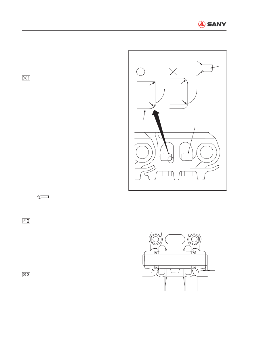
Use the tool (M) to press the master pin. 
Make sure that the protrusion of master pin 
meets the size (a). 

Master pin protrusion (a): 2.5±1 mm


Before installing the dust seal, apply 
grease (No.2 lithium base) to its contact 
surface with the bushing. 

8.11.2 Installation


Installation is to be performed in the re-
verse order of removal. 


Refer to "Testing and Adjusting", "Track 
Shoe Tension - Test and Adjust". 


Installation procedure of track shoe bolts 
and nuts

1)  Bring the R side of the track shoe nut (1) 

to the link seat surface. Both seat sur-
faces should be in close contact when 
assembling the track shoe. 


If the track shoe bolts are installed 
from the other side, the corner of nut 
will interfere with the link seat surface, 
causing the nut to raise and the bolt to 
loosen. 

2)  Tighten the bolts of track shoe to the 

torque below. 

 Track shoe bolts: 

750±30 N·m {77±3 kgf·m}

R

R

R

ZX215-1006103

Corner

Corner

Corner

Track shoe nut
(Square)

Seat surface
in close contact

a

ZX215-1006104

Disassembly and Assembly

SY215C

LC

8-53

8.12  Swing Bearing AS - Remove and Install

8.12.1 Removal

1.  Remove the swing platform assembly. 

Refer to “Swing Platform AS - Remove and 
Install” on page 8-55. 

2.  Dismount the 36 bolts (1) to remove the 

swing bearing assembly.


3.  Hoist the swing bearing assembly (2). 


  Swing bearing assembly: 314 kg

2

1

ZX215T-1006105

2

ZX215T-1006106

Disassembly and Assembly

SY215C

LC

8-54

8.12.2 Installation


Installation is to be performed in the re-
verse order of removal.


 Threads (bolt - swing bearing):

Thread adhesive (Tonson 1277)

 Mounting bolts (swing bearing):

Step 1: 

Use a pneumatic spanner to tighten the 
bolts. 

Step 2: 

Torque to: 549±59 N·m {56±6kgf·m}

1)  When a torque spanner is used to 

tighten the bolts, tighten first the four 
corners and mark them. 

2)  Other bolts will be tightened clockwise 

or counterclockwise. After one bolt is 
tightened, tighten the next one on the 
diagonal position and make a mark. 

3)  Tighten the rest bolts in this way. 


Let the S mark in the soft zone of the 
inner race of the inner ring face the 
right side, as shown in the photo, and 
install the swing bearing to the track 
frame. 


Apply grease to the inside of the gear 
ring of the swing bearing. 


All gear teeth must be covered by 
grease .

 Swing bearing: 

Grease(supramoly lithium base):15 L

Inner race soft zone

ZX215T-1006107

Disassembly and Assembly

SY215C

LC

8-55

8.13  

Swing Platform AS - Remove and Install

8.13.1 Removal

 Fully extend the arm and the bucket. Low-

er the work equipment to the ground and 
move the hydraulic lockout control lever 
to the LOCK position. 

1.  Disassemble the work equipment as-

sembly. Refer to “Work Equipment AS - 
Remove and Install” on page 8-94.     

2.  Remove the counterweight assembly. 

Refer to “Counterweight AS - Remove and 
Install” on page 8-101. 

3.  Remove the four hoses (1) of boom 

cylinder. 


Cork the hoses to prevent 

fl

 ow of oil. 

4.  Lift the boom cylinder assembly (2).

1

ZX215T-1006108

2

ZX215T-1006109

Disassembly and Assembly

SY215C

LC

8-56

5.  Remove the plate (3) and the pin (4). Lift 

the boom cylinder assembly (2) in order to 
remove it. 


Remove the boom cylinder assembly 
on the other side in the same way. 

  Boom cylinder AS: 230 kg

6.  Remove the plate (5), air intake hose (6) 

and fan guard (7). 


Removal of the swing platform requires 
removing other parts that interfere with 
the lifting of swing platform. 

3

4

ZX215T-1006110

5

7

6

ZX215T-1006111

Disassembly and Assembly

SY215C

LC

8-57

7.  Disconnect the six hoses above the 

swivel joint assembly. 

8)  Central swivel joint (port A)-

Left travel control valve (port BTL)

9)  Central swivel joint (port C)-

Left travel control valve (port ATL)

10) Central swivel joint (port F)- 

Solenoid valve

11) Central swivel joint (port G)-

Swing motor (port T)

12) Central swivel joint (port D)-

Right travel control valve (port ATR)

13) Central swivel joint (port B)-

Right travel control valve (port BTR)

8.  Remove the bolt (14).

9.  Unscrew the 32 swing platform mounting 

bolts in order to remove the swing platform 
assembly (15). Lift the swing platform as-
sembly off the machine. 


Remove the front and rear mounting 
bolts of the platform. Use a lever block 
to adjust the swing platform so that 
the platform can reach a balance  both 
longitudinally and laterally. Remove the 
last two bolts 

fi

 nally. 

 Be careful not to impact the cen-

tral swivel joint while removing the 
swing platform assembly. 

  Swing platform assembly:

9

10

11

13

12

8

14

ZX215T-1006112

15

ZX215T-1006113

Assembly

Swing Platform 

Only (Ref.)

SY215C

LC

8,427 kg

1,689 kg

Disassembly and Assembly

SY215C

LC

8-58

8.13.2 Installation


Installation is to be performed in the re-
verse order of removal.


 Clamping screws (air intake hose):

5.4~6.4 N·m {0.55~0.65 kgf·m}


 Mating surface (swing bearing): 

Flat surface sealant (Tonson 1596)

 Threads (bolt - swing platform): 

Thread adhesive: (Tonson 1277)

 Mounting bolts (swing platform):

 Step 1: Tighten the bolts with a pneumatic 

spanner.

 Step 2: tighten them again. 

490~608 N·m {50~62 kgf·m}


Hydraulic oil adding

Add through the 

fi

 ller opening the hydraulic 

oil to the specified level. Start the engine 
to circulate oil in the hydraulic system, and 
check the oil level again. 


Air bleeding

Bleed the air from the travel motor. 

For more information, see “Air in Each 
Component - Bleed” on page 6-35. 

Disassembly and Assembly

SY215C

LC

8-59

8.14  Swivel Joint AS - Remove and Install

8.14.1 Removal

 Release residual pressure in the hydrau-

lic circuit. Refer to  “Residual Pressure in 
Hydraulic Circuit - Release” on page 6-29. 


Tag each line so as to ensure correction 
installation. 

1.  Disconnect the six hoses from (1) to (6) on 

the central swivel joint of the travel motor. 

(1): Central swivel joint (port T)- 

Left travel motor (port T)

(2): Central swivel joint (port T)-

Right travel motor (port T)

(3): Central swivel joint (port B)-

Left travel motor (port PA)

(4): Central swivel joint (port D)-

Right travel motor (port PB)

(5): Central swivel joint (port A)-

Left travel motor (port PB)

(6): Central swivel joint (port C)-

Right travel motor (port PA)

2.  Disconnect the eight hoses from (7) to 

(14). 

(7): Central swivel joint (port F)-

Left travel motor (port P)

(8): Central swivel joint (port F)-

Right travel motor (port P)

(9): Central swivel joint (port G)-

Swing motor (port T)

(10): Central swivel joint (port F)- 

Solenoid valve

1

2

3

4

5

6

ZX215T-1006114

7

8

9

10

11 12

13

14

15

ZX215T-1006115

Disassembly and Assembly

SY215C

LC

8-60

(11): Central swivel joint (port C)-

Left travel control valve (port ATL)

(12): Central swivel joint (port A)-

Left travel control valve (port BTL)

(13): Central swivel joint (port D)-

Right travel control valve (port ATR)

(14): Central swivel joint (port B)-

Right travel control valve (port BTR)

3.  Remove the 

fi

 xing bolt (15). 

4.  Remove the four mounting bolts (16).

16

ZX215T-1006116

18

Transition plate

16

17

ZX215-1006117

5.  Remove the six mounting bolts (17) from 

the transition plate. Remove the swivel joint 
assembly (18).                                    

  Central swivel joint: 56 kg

Disassembly and Assembly

SY215C

LC

8-61

8.14.2 Installation


Installation is to be performed in the re-
verse order of removal. 


Install the central swivel joint facing the 
direction indicated in the illustration. 

(In the illustration, the machine is seen 
from the above.)


Oil adding (hydraulic tank)

Add through the 

fi

 ller opening the hydraulic 

oil to the specified level. Start the engine 
to circulate oil in the hydraulic system, and 
check the oil level again. 


Air bleeding

Bleed the air from the travel motor. 

For more information, see “Air in Each 
Component - Bleed” on page 6-35. 

Sprocket

Central swivel joint

B D

A C

ZX215-1006118

Disassembly and Assembly

SY215C

LC

8-62

8.15  Swivel Joint AS - Disassemble and Assemble

8.15.1 Disassembly

1.  Remove the bolt (1) and the spring washer 

(2). 

2.  Remove the cover (3).

3.  Remove the gasket (4), O-ring (5) and 

snap ring (6). 

4.  Remove the rotor (13) from the housing 

(9).


Be careful not to damage the sliding 
surface of the seal of the rotor (13). 

5.  Remove the spacer (7) and the gasket (8) 

from the housing (9). 

6.  Remove the dust seal (12) from the 

swing shaft (13). 

7.  Remove the O-ring seal (11) and the 

seals (10) from the housing (9). 

1

2
3

4

5

6

7

8

9

10

11

12

13

ZX215-1006119

ZX215-1006120

Disassembly and Assembly

SY215C

LC

8-63

8.15.2 Assembly

1.  Install the dust seal (12) on the rotor (13). 


Let the lip face the housing while 
installing the dust seal. 

2.  Install the six seals (10) in the housing 

(9). 

3.  Fix the rotor (13) on a work bench. Install 

the housing (9) on the rotor (13). 


Since the clearance between the hous-
ing (9) and the rotor (13) is approxi-
mately 0.1 mm, install the housing (9) 
on the rotor (13) slowly and vertically. 
Be careful not to damage the seals (10) 
and the O-ring seal (11). 

4.  Use a rubber hammer to tap the housing 

(9) in order to match the rotor (13) properly. 

5.  Install the spacer (7) and gasket (8) in 

the housing (9). 

6.  Install the gasket (4), O-ring seal (5) and 

snap ring (6) on the rotor (13). 

7.  Install the cover (3). Tighten the bolts (1) 

and the spring washer (2). 

 Fixing bolts: 49 N·m{5 kgf·m}

Dust seal

Lip

Body

ZX215-1006121

Disassembly and Assembly

SY215C

LC

8-64

8.16  Hydraulic Tank AS - Remove and Install

8.16.1 Removal

1.  Drain the hydraulic oil into a suitable 

container for storage or disposal. 


 Hydraulic oil: approx. 225 L

2.  Open the engine hood. 

3.  Remove the engine hood (1), cover (2) 

and control valve cover (3). 

4.  Remove the cover mounting frame (4) 

and the screen (5). 

5.  Remove the screen (6) and the partition 

frame mounting bolt (7) on the hydraulic 
tank side. 

6.  Remove the screw (8) and the travel alarm 

(9). 

7.  Remove the two oil return hoses (10) 

from the hydraulic tank. 

1

2

3

4

5

ZX215T-1006122

6

7

8

9

10

Disassembly and Assembly

SY215C

LC

8-65

8.  Disconnect the seven hoses.


(11): Oil return - pilot T block


(12): Oil return - main pump


(13): Oil return D2 - main valve


(14): Sensor - temperature


(15): Oil return - solenoid valve


(16): Oil return D1/D3 - main valve


(17): Oil return - swing motor


Disconnect the oil inlet hose (18) from 
the hydraulic tank after disconnection 
of the oil inlet tube from the pump. 


Attach each hose with an identi

fi

 cation 

tag. 


Use a sleeve nut to prevent the fitting 
and the cone seal from damage. 

9.  Remove the hose clamp (19).

10.  Lift the hydraulic tank assembly and 

remove the six bolts (20).                   


11.  Lift off the hydraulic tank assembly for 

disassembling. 

  Hydraulic tank assembly: 130 kg

11

12

13

15

16

14

17

18

ZX215T-1006125

20

ZX215T-1006127

19

ZXT225-1106008

Disassembly and Assembly

SY215C

LC

8-66

8.16.2 Installation


Installation is to be performed in the re-
verse order of removal. 


 Drain plug (hydraulic tank):

58.8~78.5 N·m {6.0~8.0 kgf·m}


After tightening the hose clamping 
screw, check that the screw should be 
in the range indicated in the illustration. 

 Screw (hose clamp):

8.8±0.5 N·m {0.9±0.05 kgf·m}


Install the hose clamp and tighten the 
screw according to the illustration on 
the right. 


 Bolt: 

245.2~308.9 N·m {25~31.5 kgf·m}


Oil adding (hydraulic tank)

Add hydraulic oil through the 

fi

 ller opening 

to the specified level. Start the engine to 
circulate oil in the hydraulic system, and 
check the oil level again.


Air bleeding

For more information, see “Air in Each 
Component - Bleed” on page 6-35. 

Screw

Up
Down

ZX215-1006128

Pipe

Clamp

Hose

Bulge

ZX215-1006129

Disassembly and Assembly

SY215C

LC

8-67

8.17  Control Valve AS - Remove and Install

8.17.1 Removal

 Lower the work equipment to the ground. 

Stop the engine. Press the release button 
of the breather valve to release residual 
pressure in the hydraulic tank. Place the 
hydraulic lockout control in the LOCK po-
sition. 


Tag each line so as to ensure correction 
installation. 

1.  Lift the hood (1). 

2.  Remove the cover (2) above the control 

valve. 

3.  Remove the engine silencing hood (3). 

4.  Remove the baffle (4) to (9) of the pres-

sure transducer and tag them.

(4): XAK Bucket DIG

(5): XBb1 Boom DOWN

(6): XAtL Travel LEFT

(7): XBa1 Arm IN

(8): XBs Swing RIGHT

(9): XAtr Travel RIGHT

4

7

8

9

ZXT225-1106011

5

6

1

2

ZXT225-1106009

3

ZXT225-1106010


Content      ..     32      33      34      35     ..