SANY Crawler Hydraulic Excavator SY215CLC (CUMMINS QSB6.7 engine). Shop Manual - page 32
 

  Index      Manuals     SANY Crawler Hydraulic Excavator SY215CLC (CUMMINS QSB6.7 engine). Shop Manual


Search            copyright infringement  


Content      ..     30      31      32      33     ..


SANY Crawler Hydraulic Excavator SY215CLC (CUMMINS QSB6.7 engine). Shop Manual - page 32


Disassembly and Assembly

SY215C

LC

8-20

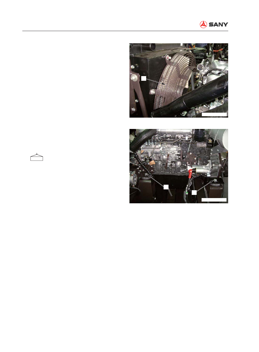
24.  Disconnect the radiator fan guard (40). 

25.  Remove the 

fi

 xing bolt (41) on each of the 

four mounting plates of the damper. Lift the 
engine and main pump assembly. 

  Engine and hydraulic pump AS:

640 kg

40

ZX215T-1006049

41

41

ZX215T-1006050

Disassembly and Assembly

SY215C

LC

8-21

8.4.2 Installation


Installation is to be performed in the re-
verse order of removal. 


Open the radiator tank cover to add cool-
ant. Also add coolant to the coolant reser-
voir. 


 Engine coolant:

approx.  22.5 L. 


Re

fi

 ll the hydraulic tank with hydraulic oil. 

 Hydraulic tank:

approx. 225 L


Start the engine to circulate the coolant 
in order release the foams, and check the 
coolant level again. 


Start the engine to circulate the hydraulic 
oil in the hydraulic system, and check the 
oil level again. 


Air bleeding 

For more information, see “Air in Each 
Component - Bleed” on page 6-35. 

Disassembly and Assembly

SY215C

LC

8-22

8.5  Final Drive AS - Remove and Install

8.5.1 Removal

1.  Remove the sprocket. Refer to “Sprocket - 

Remove and Install” on page 8-49.

  Lower the work equipment to the ground. 

Stop the engine. Operate the breather 
valve to release internal pressure. 

2.  Remove the motor cover plate (1). 

3.  Disconnect the four hoses (2) of the travel 

motor and the corresponding hose connec-
tors. 

1

ZX215-1006051

2

ZX215T-1006052

Disassembly and Assembly

SY215C

LC

8-23

4.  Remove the 30 mounting bolts from the 

final drive assembly (3), and lift the as-
sembly for disassembling. 


Be careful not to damage the surface 
of mounting seal installed on the hose 
base. 


Never use the threaded holes to lift the 
cover when lifting the 

fi

 nal drive. 

 Final Drive Assembly: 250 kg

8.5.2 Installation


Installation is to be performed in the re-
verse order of removal. 


 Mounting bolts (final drive assem-

bly):   

245~309 N·m {25~31 kgf·m}


Hydraulic oil adding

Add hydraulic oil through the 

fi

 ller opening 

to the specified level. Start the engine to 
circulate oil in the hydraulic system, and 
check the oil level again. 


Air bleeding 

For more information, see “Air in Each 
Component - Bleed” on page 6-35. 

3

ZX215-1006053

Disassembly and Assembly

SY215C

LC

8-24

8.6  Final Drive AS - Disassemble and Assemble

8.6.1 Disassembly

1.  Oil draining

Open the drain plug to drain the oil from 
the 

fi

 nal drive tank. 

 Final drive tank: approx. 4.7 L

2.  Cover

Remove the bolts. Use eyebolts 

 to the 

cover (1). 

3.  Spacer

Remove the spacer (2). 

1

ZX215-1006054

2

ZX215-1006055

Disassembly and Assembly

SY215C

LC

8-25

4.  No. 1 planetary carrier assembly

1)  Remove the No.1 planetary carrier as-

sembly (3). 

2)  Disassembly of No.1 planetary carrier 

assembly. 

i)  Remove the screws (4). Remove 

the coverplate (5) from the plan-
etary carrier assembly (6). 

ii)  Remove the thrust washer (7), gear 

(8), bearing (9), bearing inner race 
(10) and a second thrust washer 
(11). 

5.  No.1 sun gear shaft

Remove No.1 sun gear shaft (12). 

3

ZX215-1006056

9

7

4

5

10

8

11

6

ZX215-1006057

12

ZX215-1006058

Disassembly and Assembly

SY215C

LC

8-26

8.  Disassembly of No.2 planetary carrier 

assembly

1)  Remove the screws (15). Remove the 

plate (16) and the planetary gear (17) 
from the carrier assembly (22). 

2)  Remove the bearing inner race (19) 

and outer race (18). Remove the plate 
(20). 

3)  Remove the screw (21) to take the 

planetary carrier assembly (22) and the 
shim (23) from the body. 

6.  Thrust washer

Remove the thrust washer (13). 

7.  No.2 sun gear

Remove No.2 sun gear (14). 

9.  Hub assembly

1) Use eyebolts 

 to remove the hub as-

sembly (24) from the travel motor. 

13

14

ZX215-1006059

17

20

21

22

18

19

15

16

23

ZX215-1006060

24

ZX215-1006061

Disassembly and Assembly

SY215C

LC

8-27

2)  Disassemble the hub assembly as the 

following. 

i) Remove 

the 

fl

 oat seal (25). 

ii)  Remove the bearing (26) and bear-

ing (27) from the hub (28). 


Do not damage the bearing retainer 
when removing the bearing (26). 

3)  Remove the float seal (29) from the 

travel motor. 

26

25

27

28

ZX215-1006062

29

30

ZX215-1006063

Disassembly and Assembly

SY215C

LC

8-28

8.6.2 Assembly


Clean all the parts. Check that these parts 
are free from any contamination or dam-
age. Apply some engine oil to the sliding 
surface prior to installation. 

1.   Hub assembly

1)  Install the bearing 26 and bearing (27) 

by pressing them onto the hub (28). 

2) Install the 

fl

 oat seal (25). 


Remove any oil or dust from the O-ring 
or O-ring contact surface. Dry the parts 
before installing the 

fl

 oat seal. 


After installing the 

fl

 oat seal, check that 

the angle of the 

fl

 oating seal is within 1 

mm.


Apply a thin layer of engine oil to the 
sliding surface after the float seal has 
been installed. 

3)  Install the float seal (29) to the travel 

motor (30). 


See the above step 2 for the installation 
procedure.

26

25

27

28

ZX215-1006062

ZX215-1006064

29

30

ZX215-1006063

Disassembly and Assembly

SY215C

LC

8-29

4) Use eyebolts 

 to carefully place the 

hub assembly (24) onto the travel mo-
tor. Tap to press 

fi

 t the bearing. 

24

ZX215-1006061

2.   Calculation of shim thickness

1)  Measure the thickness (H) of the raised 

part of No.2 carrier assembly (22). 

2)  Measurement of raised thickness 

Apply 3000 Kg load to the bearing and 
measure the value (H) of the raised 
part of the bearing. 


Turn the hub 2-3 times before applying 
a pushing force. 


Do not use a spray gun to cushion the 
bearing.


Do not push or strike the resin retainer. 

3)  Shim thickness calculation: C=H-h. 

H

22

ZX215-1006065

h

Load 3000Kg

ZX215-1006066

Disassembly and Assembly

SY215C

LC

8-30

4)  Place the shims on the body and insert 

the dowel pin. Press the carrier assem-
bly onto the dowel pin and tighten it 
with screw (21). Apply locking adhesive 
to the threads. 

 Screw-locking adhesive: 

(Kesaixin 1277)

 Screw (21):

539±28 N·m {55±2.9 kgf·m}


Use a tensiometer to measure the tan-
gential force of hub to motor rotation. 


Tangential force: Max.294 N {30 kg}


Maximum tangential force occurs 
when the rotating direction begins 
to change.

3.   Assembly of No.2 planetary carrier 

assembly

1)  Assemble the No.2 planetary carrier 

assembly according to the following 
procedure. 


Replace the plates (20) and (16) with 
new parts.

i)  Assemble the bearing (18) and 

bearing (19) to the gear (17). As-
semble the top and bottom plates 
(16) and (20), and place the gear 
assembly into the carrier assembly 
(22). 

ii)  Tighten the screw (15). 

 Screw (15):

539±28 N·m {55±2.9 kgf·m}


Check the 

fl

 exibility of gear (17) 

after assembling the planetary 
carrier assembly. 

Tensiometer

ZX215-1006067

17

20

21

22

18

19

15

16

23

ZX215-1006060

Disassembly and Assembly

SY215C

LC

8-31

13

14

ZX215-1006059

6.   No. 1 sun gear shaft 

Install No.1 sun gear shaft (12).

4.   Thrust washer

Install the thrust washer (13). 

5.   No.2 sun gear

Install No.2 sun gear (14). 

12

ZX215-1006058

7.   No.1 planetary carrier assembly 

1)  No. 1 planetary carrier assembly is as-

sembled as the following.


Replace the thrust washers (7) and 
(11) with new parts. 

i)  Assemble the bearings (9) and (10) 

onto the gear (8). Assemble the top 
and bottom thrust washers (7) and 
(11). Place the gear assembly into 
the carrier assembly (6). 

ii)  Fix the coverplate (5) to the carrier 

assembly (6) with screw (4). 

9

7

4

5

10

8

11

6

ZX215-1006057

Disassembly and Assembly

SY215C

LC

8-32

3

ZX215-1006056

2

ZX215-1006055

Torque wrench

ZX215-1006068

2)  Install No.1 planetary carrier assembly 

(3). 

8.  Spacer

Install the spacer (2). 

9.  Cover

Use eyebolts 

 to assemble the cover (1). 

Use a torque spanner to tighten the bolts. 

 Bolts:

73.4±3.63 N·m {7.5±0.4 kgf·m}

10.  Oil adding 

Tighten the drain plug and add engine oil 
through the 

fi

 ller. 

 Final drive case: approx. 4.7 L


Check the oil level after the 

fi

 nal  drive 

has been successfully installed to the 
chassis. 

Disassembly and Assembly

SY215C

LC

8-33

8.7  Swing Motor and Swing Drive AS - Remove and Install

8.7.1 Removal

  Release the residual pressure in the hy-

draulic circuit. Refer to “Residual Pres-
sure in Hydraulic Circuit - Release” on 
page 6-29. 

  Lower the work equipment to the ground. 

Stop the engine. Press the release button 
of the breather valve to release residual 
pressure in the hydraulic tank. Place the 
hydraulic lockout control in the LOCK po-
sition. 

1.  Disconnect the hoses (1) to (7). 

1)  Between hydraulic tank and swing mo-

tor (port DR)

2)  Between central swivel joint and swing 

motor (port DR)

3)  Between swing motor and main valve 

(port M)

4)  Between swing motor and main valve 

(port HA)

5)  Between swing motor and main valve 

(port HB)

6)  Between swing motor and main valve 

Px port (port SH)

7)  Between swing motor and solenoid 

valve block (port PG) 

2.  Remove the 11 

fi

 xing bolts (8). 

3.  Lift the swing motor and swing drive 

assembly (9) for disassembling. 


Slowly lift the swing motor and swing 
drive assembly in order to avoid dam-
aging the hoses and other parts. 

 Swing motor and swing drive 

assembly: 260 kg

1

3

4

2

5

6

7

ZXT225-1106002

8

9

ZXT225-1106003

Disassembly and Assembly

SY215C

LC

8-34

8.7.2 Installation


Installation is performed in the reverse or-
der of removal. 


 Mounting bolts (swing motor and 

swing drive assembly):

490~608 N·m {50~62 kgf·m}


Hydraulic oil adding

Add hydraulic oil through the 

fi

 ller opening 

to the specified level. Start the engine to 
circulate oil in the hydraulic system, and 
check the oil level again. 


Air bleeding

For more information, see “Air in Each 
Component - Bleed” on page 6-35. 

Disassembly and Assembly

SY215C

LC

8-35

8.8  Swing Motor and Swing Drive AS - Disassemble and Assemble

8.8.1 Disassembly

1.   Draining of oil

Open the drain plug to drain the oil from 
the  swing drive. 

 Swing drive: approx. 4.4 L

2.   Swing motor assembly

1)  Place the swing motor and swing drive 

assembly on a suitable cribbing. Be 
careful not to damage the drive gear or 
let it contact the ground. 

2)  Unscrew the 14 bolts in order to re-

move the swing motor assembly (1). 

  Swing motor assembly: 62 kg

3.   No.1 sun gear

1)  Remove No.1 sun gear (2).

2

ZX215-1006072

1

ZX225-1006077


Content      ..     30      31      32      33     ..