SANY Crawler Hydraulic Excavator SY215CLC (CUMMINS QSB6.7 engine). Shop Manual - page 35
 

  Index      Manuals     SANY Crawler Hydraulic Excavator SY215CLC (CUMMINS QSB6.7 engine). Shop Manual


Search            copyright infringement  


Content      ..     33      34      35      36     ..


SANY Crawler Hydraulic Excavator SY215CLC (CUMMINS QSB6.7 engine). Shop Manual - page 35


Disassembly and Assembly

SY215C

LC

8-68

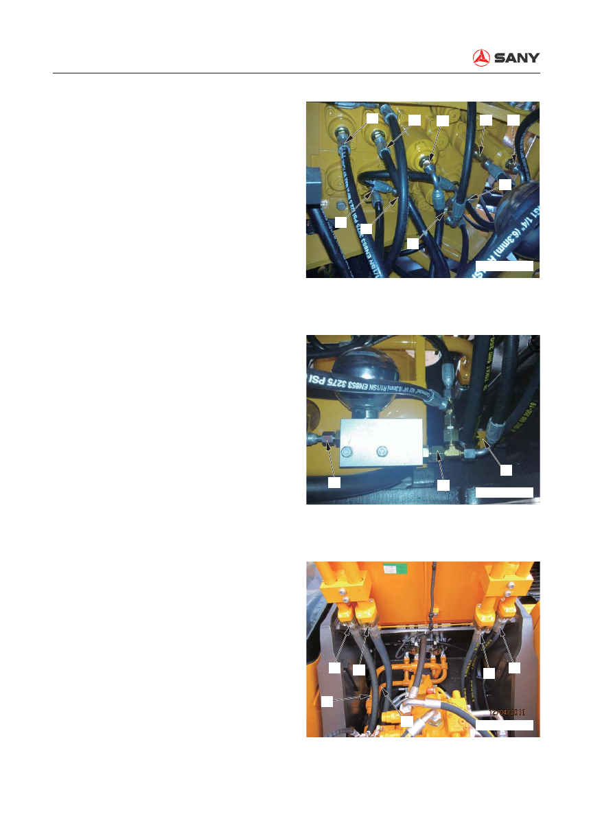
5.  Disconnect the pilot hoses (10) to (18) 

and tag them properly. 

(10): XBtr Travel RIGHT

(11): XAs Swing LEFT

(12): PSP Swing priority

(13): XAa1 Arm OUT

(14): XBp2 Bucket con

fl

 uence

(15): XBtL Travel LEFT

(16): XAb1 Boom UP

(17): XBK Bucket DIG

(18): XAa2 Arm OUT

6.  Remove the port (19) (accumulator to 

solenoid valve), port (10) (pilot 

fi

 lter to ac-

cumulator). Remove hose clip (21) of  the 
central swivel joint.

7.  Remove bucket hoses (22) and (23) and 

seal the ports.

8.  Remove arm hoses (24) and (25) and 

seal the ports. 

9.  Remove boom hoses (26) and (27) and 

seal the ports. 

ZXT225-1106012

10

11

12

13

14

15

16

17

18

ZXT225-1106013

19

20

21

ZXT225-1106014

22

24

26

27

25

23

Disassembly and Assembly

SY215C

LC

8-69

10.  Remove central swivel joint hoses (28), 

(29), (30) and (31). Remove travel speed 
switching hose (32) and seal the ports. 

11.  Remove swing motor hoses (33) and 

(34). Remove swing motor oil complement 
hose (35). Seal the ports properly. 

12.  Remove pipe (36) (main valve to radia-

tor). 

32

30

31

28

29

ZXT225-1106015

ZXT225-1106016

33

35

34

ZXT225-1106017

36

Disassembly and Assembly

SY215C

LC

8-70

13.  Remove pipe (37) (main valve to return 

oil tank). Seal the ports properly. 

14.  Remove hydraulic pump hoses (38) and 

(39). 

15.  Remove hoses (40) to (44) on the sole-

noid valve and tag them properly.

(40): PPC lockout valve

(41): Main valve PnA2

(42): Main valve XBP2

(43): Main valve PSP

(44): Travel PT port

ZXT225-1106018

37

ZXT225-1106019

38

39

ZXT225-1106020

44 43 42 41 40

Disassembly and Assembly

SY215C

LC

8-71

16.  Remove the fixing bolts (45). Lift the 

control valve assembly (46) for disassem-
bling. 

  Control valve assembly: 220 kg

8.17.2 Installation


Installation is to be performed in the re-
verse order of removal. 


Oil adding (hydraulic tank)

Add hydraulic oil through the 

fi

 ller opening 

to the specified level. Start the engine to 
circulate oil in the hydraulic system, and 
check the oil level again.


Air bleeding

Bleed the air from the circuit between the 
valve and the hydraulic cylinder. For more 
information, see “Air in Each Component - 
Bleed” on page 6-35. 

ZXT225-1106021

45

46

45

Disassembly and Assembly

SY215C

LC

8-72

8.18  

Hydraulic Pump AS - Remove and Install

8.18.1 Removal

 Lower the work equipment to the ground 

and stop the engine. Press the release 
button of the breather valve to release re-
sidual pressure in the hydraulic tank. 

 Disconnect the cable from the negative (-) 

post of the battery before performing the 
job. 


Tag each line so as to ensure correction 
installation. 

1.  Remove the oil inlet 

fi

 lter element from the 

hydraulic tank and stop oil out

fl

 ow with an 

oil stopper. 


If no oil stopper is used, remove the 
drain plug and drain the oil from the 
hydraulic tank and from circuits. 

 Hydraulic tank: Approx. 225 L

2.  Lift the hood (1). 

Oil stopper

ZX215-1006144

1

ZX215T-1006145

Disassembly and Assembly

SY215C

LC

8-73

3.  Remove the pin (2) and the bolts (3). Lift 

the engine hood in order to remove it. 

4.  Remove the right upper cover (4). 

5.  Disconnect the hose (5) supplying oil to 

the lower proportional valve and the hose 
(6) delivering oil from the pilot pump. 

2

ZX215T-1006146

3

4

ZX215T-1006147

5

6

ZX215T-1006148

Disassembly and Assembly

SY215C

LC

8-74

6.  Disconnect the shutdown wire (7). 

7.  Remove the right door (8). 

8.  Remove the hydraulic pump cover (9). 

9.  Disconnect the oil drain hose (10) and 

seal the openings properly. 

10.  Disconnect the high-pressure hoses (11) 

and (12) connecting to the control valve, 
and seal the openings properly. 

11.  Disconnect the harness (13) of the pres-

sure transducer. 

12.  Disconnect the pilot pump oil inlet hose 

(14) and seal the openings properly. 

13.  Disconnect the pilot pump oil inlet tube 

(15) and seal the openings properly. 

7

ZX215T-1006149

9

8

ZX215T-1006150

10

11

12

13

14

15

ZX215T-1006151

Disassembly and Assembly

SY215C

LC

8-75

14.  Disconnect the solenoid valve harnesses 

(16) and (17). Remove the cable straps (18) 
and (19). 

15.  Remove the four bolts (20) of the hydrau-

lic pump. Lift the hydraulic pump assembly 
(21) to remove it.                                  


  Hydraulic pump assembly: 112 kg

16

17

18

19

ZX215T-1006152

20

21

ZX215T-1006153

Disassembly and Assembly

SY215C

LC

8-76


 Mating surface (hydraulic pump 

housing): 

Gasket sealant: (Loctite 515) 


Oil adding (hydraulic tank)

Add hydraulic oil through the 

fi

 ller opening 

to the specified level. Start the engine to 
circulate oil in the hydraulic system, and 
check the oil level again.

 Hydraulic tank: approx. 225 L


Air bleeding

For more information, see “Air in Each 
Component - Bleed” on page 6-35. 

8.18.2 Installation


Installation is to be performed in the re-
verse order of removal. 


After tightening the hose clamping 
screw, check that the screw should be 
in the range indicated in the illustration.

 Screw (hose clamp):

8.8±0.5 N·m {0.9±0.05 kgf·m}


Install the hose clamp and tighten the 
screw according to the illustration on 
the right. 

Screw

Up
Down

ZX215-1006128

Pipe

Clamp

Hose

Bulge

ZX215-1006129

Disassembly and Assembly

SY215C

LC

8-77

8.19  Middle Oil Seal (Hydraulic Pump Input Shaft)- Remove and Install

8.19.1 Removal

1.  Remove the hydraulic pump assembly (1). 

Refer to “Hydraulic Pump AS - Remove 
and Install” on page 8-72. 

2.  Remove the screw (2). Remove the bear-

ing cover (3). 

3.    Pry  the  oil  seal  (4)  out  with  a  screwdriver.                           


Be careful not to damage the shaft 
while prying the oil seal. 

8.19.2 Installation


Installation is to be performed in the re-
verse order of removal. 


 Seal lip: 

grease (No.1 Calcium base grease)

 Seal circumference: 

grease (No.1 Calcium base grease)


Apply a thin layer of grease to the oil 
seal circumference. 

1

2

3
4

ZX215-1006154

4

ZX215-1006155

Disassembly and Assembly

SY215C

LC

8-78

8.20  Pilot Valve AS (Work Equipment) - Disassemble and Assemble


This section discusses only the precautions 
when reassembling the work equipment 
pilot valve assembly. 

8.20.1 Assembly


Reassembly of the work equipment pilot 
valve assembly 

1.  Install the plate (9) in the valve body (8) 

with O-ring seal. Tighten the socket bolt 
(10). 

 Socket bolt: 

25~33 N·m {2.55~3.36 kgf·m}

2.  Insert the spring (7) into the spool hole 

in the valve body (8). Put the spool (6) in 
the spring. Install the plug (5) on the spool. 
Push the plug (5) to the spool hole. 

3.  Install the plate (4) on the plug (5). 

Tighten the U-joint (3). 

4.  Install the plate (2). Align the position of 

the plate (2) and tighten the nut (1). 

 Nut: 

98~133 N·m {10~13.5 kgf·m}


Location of each oil port is stamped on 
the bottom of valve body. 

1

2

3

4

5

6

7

8

9

10

ZX215T-1006156

Disassembly and Assembly

SY215C

LC

8-79


Apply the thread adhesive (Tonson 
1277) to two points on the inner 
threads, as indicated in the illustration 
below. The amount of application is 
approximately 0.02 g. 

 U-joint (3):

98~133 N·m {10~13.5 kgf·m}


Tightening is to be made to the speci-

fi

 ed torque. 

 Contact surface between plug (5) 

and plate (2): 

Grease 0.3~0.8cc (No.1 Calcium base 
grease)


See also “Pilot Valves (Work Equipment 
and Swing) - Adjust” on page 6-25. 

 Plug (5) circumference: 

Grease (No.1 Calcium base grease)

 U-joint moving surface: 

Grease (No.1 Calcium base grease)

 Threads in valve body: 

Thread adhesive (Tonson 1277)

5~7 mm

ZX215-1006157

Disassembly and Assembly

SY215C

LC

8-80

8.21  Pilot Valve AS (Travel) - Disassemble and Assemble


This section discusses only the precau-
tions when reassembling the travel pilot 
valve assembly. 

1

2

3

4

5

6

7

8

9

Plunger

ZX215T-1006158

Disassembly and Assembly

SY215C

LC

8-81

8.21.1 Assembly


Reassembly of the pedal pilot valve as-
sembly

1.  Install the spring (8) into the spool installa-

tion hole in the body assembly (9). Install 
the spool (7). Place the cover assembly (6) 
on the spool and press the cover assembly 
(6) with a hand. 

2.  Install the cover (4) after aligning the holes. 

Tighten the socket bolts (1). 

 Bolt (socket): 

98~114 N·m {10~11.6 kgf·m}

3.  Install the dust ring (3) on the plug. 

Install the cover (2) and fix the cover (2) 
with the camshaft (5).

 Contact surface between the plug 

and the dust ring (5): 

Grease (No.1 Calcium base grease)

Disassembly and Assembly

SY215C

LC

8-82

8.22  Hydraulic Cylinder AS - Disassemble and Assemble

Special tools

Application

Tool Shape

Necessity

Quantity

Pulling out/pushing 
in the bushing


ZX215-1006159

1

Press 

fi

 tting the 

dust ring


ZX215-1006160

1

O-ring seal correc-
tion


Inserting tool

Correcting tool


ZX215-1006161

1

Inserting the cylin-
der head


ZX215-1006162

1

Inserting the piston


ZX215-1006163

1

Disassembly and Assembly

SY215C

LC

8-83

8.22.1 Disassembly

1.  Drain the oil and remove the tubing. 

2.  Fix the cylinder. 


Fix the cylinder in a vertical or level 
manner. A vertically fixed cylinder can 
be disassembled and assembled easily. 


The pin bore in the head end can be 
used for fixing of the cylinder. The pin 
roll can prevent the cylinder from turn-
ing. 


Remove the tubing in case of tubing 
interference while 

fi

 xing the cylinder. 

3.  Removal of cylinder head


Unscrew the bolts with Allen Wrench. 


Using an extension rod, as shown in 
the illustration on the right, will make 
the work easy. 

Fix the cylinder

ZX215-1006164

Approx 1.5m

ZX215-1006165


Content      ..     33      34      35      36     ..