SANY Crawler Hydraulic Excavator SY215CLC (CUMMINS QSB6.7 engine). Shop Manual - page 20
 

  Index      Manuals     SANY Crawler Hydraulic Excavator SY215CLC (CUMMINS QSB6.7 engine). Shop Manual


Search            copyright infringement  


Content      ..     18      19      20      21     ..


SANY Crawler Hydraulic Excavator SY215CLC (CUMMINS QSB6.7 engine). Shop Manual - page 20


Structure and Function

SY215C

LC

4-220

XP21511018H

5

4

3

2

1

* * * * *

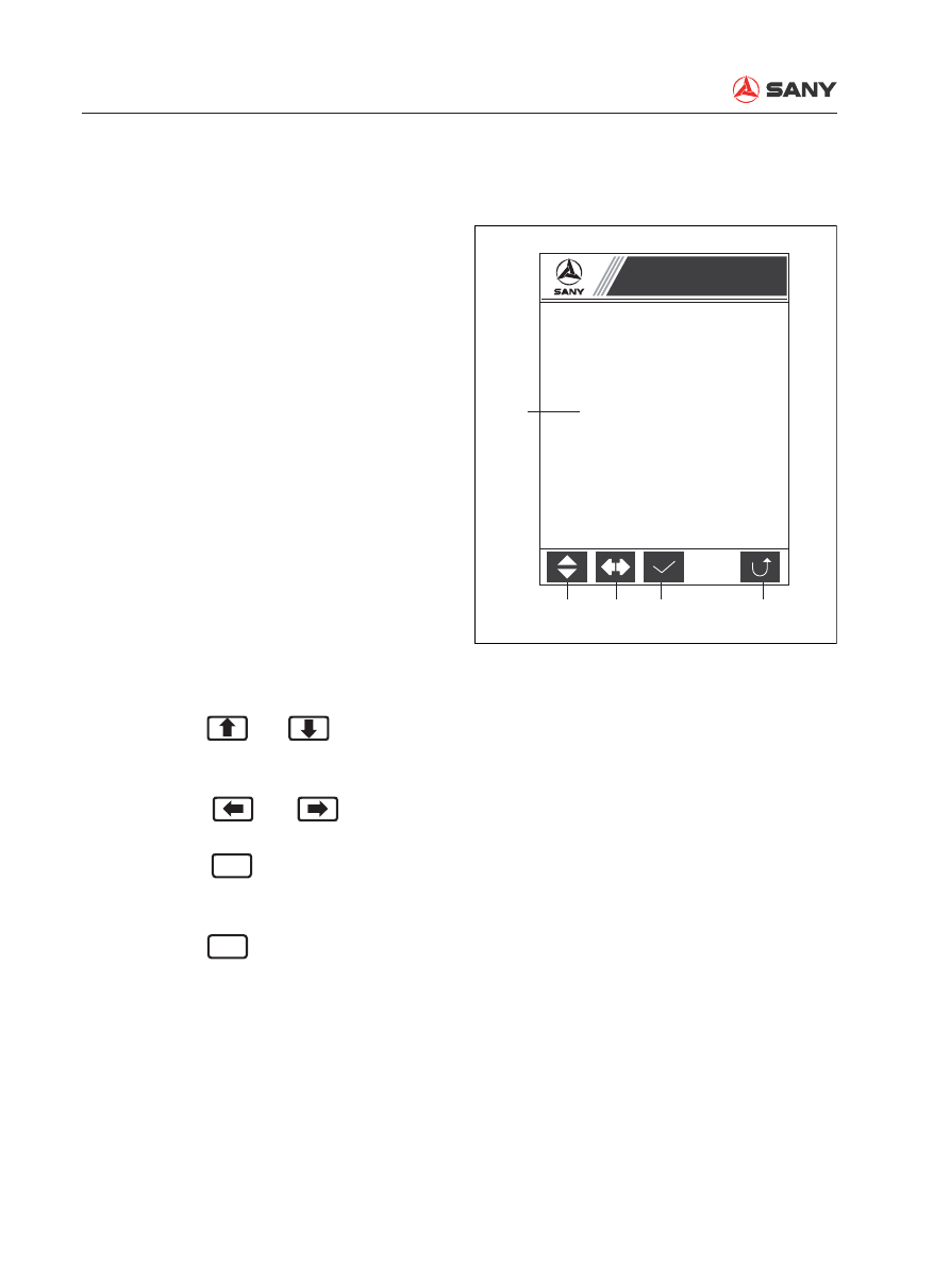
System Setup

Please enter password:

Screen display

1.  A 5-digit password. Each digit is indicated 

by an asterisk (*) standing for a value 
from 0 to 9. A numeral appears at the digit 
where the cursor is located while the other 
four digits are in asterisk. 

2.  Change the value of the digit where the 

cursor is located. 

3.  Move the cursor. 

4.  Check the password and go to Machine 

Con

fi

 guration if the password is correct, or 

tell the user to enter the correct password, 
if the password is wrong.

5.  Return to System Setup. 

Keypad input


Press F1 or 

 and 

 to change the 

value of the digit where the cursor is locat-
ed.


Press F2 or 

 and 

 to move the 

cursor.


Press F3 or 

Enter

 to check the validity of 

the password and go to Machine Con

fi

 gu-

ration if it is correct.


Press F5 or 

ESC

 to return to System Set-

up.

4.10.3.19 Machine Confi guration Password

Function

Enter the password before accessing the sys-
tem con

fi

 guration page.

Structure and Function

SY215C

LC

4-221

4.10.3.20 Machine Confi guration

Function

Machine con

fi

 guration information. 

Screen display

1.  List of machine con

fi

 guration information.

2.  Return to System Setup.

Keypad input


Press F5 or 

ESC

 to return to System Set-

up.

XP21511019H

2

1

Machine Model 

Machine S/N       

Engine Model 

Hyd System Model

Controller Model

Machine Configuration

Structure and Function

SY215C

LC

4-222

Screen display

1.  A 5-digit password. Each digit is indicated 

by an asterisk (*) standing for a value 
from 0 to 9. A numeral appears at the digit 
where the cursor is located while the other 
four digits are in asterisk. 

2.  Change the value of the digit where the 

cursor is located. 

3.  Move the cursor. 

4.  Check the password and go to Service 

Hour Calibration if the password is correct, 
or tell the user to enter the correct pass-
word, if the password is wrong.

5.  Return to System Setup. 

Keypad input


Press F1 or 

 and 

 to change the 

value of the digit where the cursor is locat-
ed.


Press F2 or 

 and 

 to move the 

cursor.


Press F3 or 

Enter

 to check the validity of 

the password and go to Service Hour cali-
bration if it is correct.


Press F5 or 

ESC

 to return to System Set-

up.

4.10.3.21  Service Hour Calibration Pass-

word

Function

Enter the password before accessing the ser-
vice hour adjustment page.

XP21511020H

5

4

3

2

1

* * * * *

System Setup

Please enter password:

Structure and Function

SY215C

LC

4-223

XP21511021H

4

3

1

2

Current Service Hours

Use [

] [

] [

] AND [

] to calibrate service hours.

100 h 50 m

Calibration Service Hours

100 h 50 m

Service Hour Calibration

4.10.3.22  Service Hour Calibration

Function

Adjust total service hours. 

Screen display

1.  Current total service hour reading in the 

controller.

2.  Adjusted service hour.

3.  Update the current total service hour read-

ing with the adjusted service hour.

4.  Return to System Setup.

Keypad input


Press F1 or 

Enter

 to confirm and update 

service hour reading. “Adjustment 

fi

 nished. 

Re-energize the system” is displayed on 
the bottom.


Press F5 or 

ESC

 to return to System Set-

up.

Structure and Function

SY215C

LC

4-224

XP21511022H

5

4

3

2

1

* * * * *

System Setup

Please enter password:

Screen display

1.  A 5-digit password. Each digit is indicated 

by an asterisk (*) standing for a value 
from 0 to 9. A numeral appears at the digit 
where the cursor is located while the other 
four digits are in asterisk. 

2.  Change the value of the digit where the 

cursor is located. 

3.  Move the cursor. 

4.  Check the password and go to Machine 

Con

fi

 guration Calibration if the password is 

correct, or tell the user to enter the correct 
password, if the password is wrong.

5.  Return to System Setup. 

Keypad input


Press F1 or 

 and 

 to change the 

value of the digit where the cursor is locat-
ed.


Press F2 or 

 and 

 to move the 

cursor.


Press F3 or 

Enter

 to check the validity of 

the password and go to Machine Con

fi

 gu-

ration Calibration if it is correct.


Press F5 or 

ESC

 to return to System Set-

up.

4.10.3.23  Machine Confi guration Calibration 

Password

Function

Enter the password before accessing the ma-
chine con

fi

 guration calibration page.

Structure and Function

SY215C

LC

4-225

4.10.3.24  Machine Confi guration Calibration

Function

Adjust machine con

fi

 guration when the moni-

tor is installed. 

Screen display

1. Machine con

fi

 guration information.

2.  Adjust machine model.

3.  Adjust engine model.

4.  Adjust hydraulic system model.

5.  Adjust controller model.

6.  Save machine con

fi

 guration adjustment.

Keypad input


Press F1 to alter machine model.


Press F2 to alter engine model


Press F3 to alter hydraulic system model.


Press F4 to alter controller model.


Press F5 to save machine configuration 
adjustment. “Adjustment finished. Re-
energize the system” is displayed on the 
bottom.


Press 

 or 

 to increase or de-

crease machine number by 100.


Press 

 or 

 to increase or de-

crease machine number by 1. Keep them 
pressed to quicken the increase or de-
crease.


Press 

ESC

 to return to System Setup.


Press 

Enter

 to move the cursor between 

different blocks in the machine number.

XP21511024H

1

6

2

3

4

5

Machine Model

Engine Model

Hyd System Model

Controller Model

Machine S/N

Use [

] [

] [

] AND [

] to change machine S/N.

Machine Config Calibration

Model

Engine

Hyd

Ctrl

Structure and Function

SY215C

LC

4-226

Remark:

Machine number is composed of four parts: 
Year of production, Machine code, Tonnage 
code, Alteration code, Serial number and Tail 
number “8”.

1. Press 

Enter

 to switch between Year of pro-

duction, Machine code and Serial number. 
The selected block keeps blinking.

2.  When Year of production or Alteration 

code is selected, press 

 or 

 to 

increase or decrease the number by 1.

3.  When Tonnage code is selected, press 

 or 

 to increase or decrease the 

number by 1, or press 

 or 

 to in-

crease or decrease the number by 100. 

4.  When Tonnage code is selected, press 

 or 

 to increase or decrease the 

number by 1, or press 

 or 

 to in-

crease or decrease the number by 100.

5.  The machine number can be reduced to 

four digits. Press 

 or 

 to switch 

between different parts. Press 

 or 

 to increase or decrease the num-

bers. The first digit from the left can be 
adjusted from 0 to 9 and from A to Z. The 
last three digits can be adjusted from 0 to 
9. When the number exceeds 9999, letters 
A, B, C, D, E to Z are used to stand for 10 
thousand, 11 thousand, 12 thousand, 13 
thousand, 14 thousand, 15 thousand and 
so on. e.g. 10,000 is indicated by A000, 
11,020 is indicated by B020, 12,999 is indi-
cated by C999. 

Structure and Function

SY215C

LC

4-227

1

2

XP21511035H

Hyd Oil Temp

Hydraulic Oil Temp:

4.10.3.25  Hydraulic Oil Temperature

Function

Display hydraulic oil temperature. 

Screen display

1.  Hydraulic oil temperature.

2.  Return to System Setup.

Keypad input


Press F5 or 

ESC

 to return to System Set-

up.

Structure and Function

SY215C

LC

4-228

XP21511025H

1

Machine Model

Machine S/N

Lockout State: Level 1 

Current Time

System Lockout

System locked! 

Please contact manufacturer to unlock your machine. 

All keys are disabled in lockout state.

XP21511026H

1

Machine Model

Machine S/N

Lockout State: Level 2 

Current Time

System Lockout

System locked! 

Please contact manufacturer to unlock your machine. 

All keys are disabled in lockout state.

4.10.3.26  System Lockout Level 1

Function

The machine is under level 1 lockout state. All 
keys are disabled. 

Screen display

1. Machine con

fi

 guration information, lockout 

level and current time.

Remark


After 5 seconds, the screen displays lock-
out level: Lockout Level 1, Lockout Level 2 
or Unlocked.

4.10.3.27  System Lockout Level 2

Function

The machine is under level 2 lockout state. All 
keys are disabled. 

Screen display

1. Machine con

fi

 guration information, lockout 

level and current time.

Remark


After 5 seconds, the screen displays lock-
out level: Lockout Level 1, Lockout Level 2 
or Unlocked.

Standard Values

Standard Values

SY215C

LC

5-1

5 Standard Values

5.1  Standard Values for Chassis-related Parts .............................................................. 5-3

Standard Values

SY215C

LC

5-2

WARNING

Always read the Safety section of this man-
ual before attempting to operate or service 
this equipment. Failure to do so could re-
sult in machine damage, personnel injury 
or death.

Standard Values

SY215C

LC

5-3

Categ.

Item

Measurement condition

Unit

Std. value for 

new machine

Permis-

sible value

       Engine Speed

2 pumps at relief


Engine coolant temperature: Within 
operational range


Hydraulic oil temperature: Within 
operational range


Engine running at high idle


Heavy-load operating mode (H)


Arm-in relief condition

rpm

2,000±50

2,000±50

Speed when auto 
deceleration is oper-
ated


Engine running at high idle


Auto idling switch on 


All control levers neutral

rpm

1,200±50

1,200±50

Spool Stroke

Boom control valve


Engine stopped


See Control valve 
on pg 4-9.

UP

mm

11.5±0.5

11.5±0.5

DOWN

mm

9.5±0.5

9.5±0.5

Arm control valve

IN

mm

11.5±0.5

11.5±0.5

OUT

mm

9.5±0.5

9.5±0.5

Bucket control valve

DIG/DUMP

mm

9.5±0.5

9.5±0.5

Swing control valve

Travel (L&R)

mm

9.5±0.5

9.5±0.5

Travel control valve

Forward &

Reverse

mm

9.5±0.5

9.5±0.5

Control Lever stroke

Boom control lever


Engine stopped


Control lever grip at center


Max. reading up to stroke end (ex-
cept lever play in NEUTRAL  posi-
tion)

mm

80±10

80±10

Arm control lever

mm

80±10

80±10

Bucket control lever

mm

80±10

80±10

Swing control lever

mm

80±10

80±10

Travel control lever

mm

115±12

115±12

Play of control lever


Engine stopped


Slightly push the 
control lever with 
your hand. Stop 
pushing when you 
feel clear resis-
tance 


Max. reading up 
to 

stroke end

Work Equip-

ment

mm

Max.15

Max.20

Stroke

mm

Max.20

Max.25

5 STANDARD VALUES

5.1  Standard Values for Chassis-related Parts

Standard Values

SY215C

LC

5-4

Categ.

Item

Measurement condition

Unit

Std. value for 

new machine

Permis-

sible value

Operating Force of Control Lever/

Pedal

Boom control 
lever


Hydraulic oil temp: Within operational 
range


Engine running at high idle


Control lever grip at center


Pedal at tip


Max. reading at stroke end

N

{kg}

Max.19.6

{Max.2.0}

Max.24.5

{Max.2.5}

Arm control 
lever

Max.19.6

{Max.2.0}

Max.24.5

{Max.2.5}

Bucket con-
trol lever

Max.15.6

{Max.1.6}

Max.21.6

{Max.2.2}

Swing control 
lever

Max.15.6

{Max.1.6}

Max.21.6

{Max.2.2}

Travel control 
lever

Max.30.4

{Max.3.1}

Max.39.2

{Max.4.0}

Travel control 
pedal

Max.93.1

{Max.9.5}

Max.107.6

{Max.11}

Hydraulic Pressure

Unloaded 
pressure


Hydraulic oil temp: Within operational 
range


Engine running at high idle


Working mode: H 


All control levers in neutral position


Hydraulic pump output pressure

MPa

{kg/cm²}

0 – 1.0 

0 – 2.0

Boom relief


Hydraulic oil temp: Within operational 
range


Operate corresponding control lever 
after engine runs at high idling speed.


Working mode: H 


Hydraulic pump output pressure with 
all measurement circuits relieved

34.3 ± 1.0

{350 ± 10}

33.3 – 35.3

{340 – 360}

Arm relief

34.8 ± 1.0

{355 ± 10}

33.3 – 36.8

{340 – 375}

Bucket relief

34.8 ± 1.0

{355 ± 10}

33.3 – 36.8

{340 – 375}

Swing relief


Hydraulic oil temp: Within operational 
range


Operate corresponding control lever 
after the engine runs at high idling 
speed.


Working mode: H 


Hydraulic pump output pressure with 
all measurement circuits relieved

25.5 ± 1.0

{261 ± 10}

24.5 – 27.5

{250 – 280}

Travel relief

33.4 ± 1.0

{342±10}

32.4 – 34.4

{330 – 351}

Control circuit 
source pres-
sure


Hydraulic oil temp: Within operational 
range


Engine running at high idle


Self pressure reducing valve output 
pressure with all control levers in 
NEUTRAL position

3.9±0.2

{40±2}

3.7 – 4.1

{37 – 41}

Standard Values

SY215C

LC

5-5

Categ.

Item

Measurement condition

Unit

Std. value for 

new machine

Permis-

sible value

Swing

Swing 
brake 
angle


Hydraulic oil temp: Within operational range


Engine running at high idle


Working mode: H


Swing circle misalignment amount when stopping 
after one turn


For measuring posture see Swing 1 on Pg. 4-10.


Deg.

mm

Max.100

 (—) 

Max. 130

 (—) 

Time 
taken 
to start 
swing


Hydraulic oil temp: Within operational range


Engine running at high idle


Working mode: H


Time required for passing points 90°and 
180° from starting point 


For measuring posture see Swing 1 on Pg. 
4-10.


90° sec.

3.1 ± 0.3

Max.3.7

180° sec.

4.4 ± 0.4

Max.5.5

Time 
taken to 
swing


Hydraulic oil temp: Within operational range


Engine running at high idle


Working mode: H


Time required for 5 turns after making initial 1 
turn


For measuring posture see Swing 1 on Pg. 4-10.


sec.

28 ± 3.5

Max.34

Hydraulic 
drift


Hydraulic oil temp: Within operational range


Engine stopped


Keeping the upper structure transverse on a 
grade of 15°. For more information see Swing 2 
on Pg. 4-11. 


Notching a mating mark on inner and outer races 
of the swing circle


Mating mark misalignment amount during 5 min.


mm

0

0

Motor 
leakage


Hydraulic oil temp: Within operational range


Engine running at high idle


Swing lockout switch: ON


Leakage amount for 1 minute during swing relief

ml/

min

Max.5

Max.10

T

ravel

Travel 
speed
(unload-
ed)


Hydraulic oil temp: Within operational range


Engine running at high idle


Working mode: H


Time required for track shoes to make 5 
turns after making one initial idle turn


For more information on measuring posture 
see Travel 1 on Pg. 4-9.

Lo

sec.

51.3 ± 5.1

46.2 - 60.4

Hi

28.0 ± 1.4

26.6 - 31.4

Standard Values

SY215C

LC

5-6

Cat.

Item

Measurement Condition

Unit

Std. value for 

new machine

Permis-

sible value

T

ravel

T

ravel speed

(Actual run)


Hydraulic oil temp: Within operational range


Engine running at high idle


Working mode: H


Level ground


Time required for traveling 10m after 10m trial run


For measuring posture see Swing 2 on Pg. 4-11.

Lo

sec.

20 ± 2.5

17.5~22.5

Hi

13 ± 2.5

11.5~15.5

Deviation


Hydraulic oil temp: Within operational range


Engine running at high idle


Working mode: H


Travel Speed: Low


Hard level ground


Amount of deviation (

χ

) while traveling 20m after initial 

10m trial run


For measuring posture see Travel 2/3 on Pg. 4-9/10. 

mm

Max.800

Max.900

Hydraulic drift


Hydraulic oil temp: Within operational range


Engine stopped


Park the machine on a grade of 12°, with the sprocket 
in the downhill direction


Measure the sliding distance for 5 minutes


For measuring posture see Travel 4 on Pg. 4-10.

mm

0

0

Leakage of 

travel motor


Hydraulic oil temp: Within operational range


Engine running at high idle


Traveling with the sprocket locked


Oil leakage amount for one minute with traveling in re-
lief condition

mm

13.6

27.2

W

ork Equipment

Hydraulic drift

Bucket 

tips


Hydraulic oil temp: Within operational range


Flat and level ground


Bucket full of earth or with rated load (0.8m

³

: 1,440 kg)


Boom horizontal, arm fully retracted and bucket cylin-
der fully extended


Engine stopped


Work equipment control lever in neutral position


Measure total amount of falling for 15 minutes by mea-
suring the falling every 5 minutes immediately after 
initial setting


Bucket tip lower distance


Boom cylinder: Cylinder retracting distance


Arm cylinder: cylinder extending distance


Bucket cylinder: cylinder retracting distance


For measuring posture see Work Equipment 1 on Pg. 
4-11

mm

Max.600

Max.900

Boom 

cylinder

mm

Max.20

Max.27

Arm cylin-

der

mm

Max.20

Max.20

Bucket cylinder

mm

Max.35

Max.40

Standard Values

SY215C

LC

5-7

Categ.

Item

Measurement condition

Unit

Std. value for 

new machine

Permis-

sible value

W

ork Equipment

W

ork Equipment Speed

Boom


Hydraulic oil temp: Within operation-
al range


Engine running at high idle


Working mode: H


Time required for the bucket to raise 
from the ground to its stroke end


For measuring posture see Work 
Equipment 2 on Pg. 4-11. 

UP

sec.

3.4 ± 0.4

Max. 4.8 

Arm


Hydraulic oil temp: Within operation-
al range


Engine running at high idle


Working mode: H


Time required from dumping stroke 
end to digging stroke end


For measuring posture see Work 
Equipment 3 on Pg. 4-12. 

IN

sec.

2.6 ± 0.4

Max. 3.3

OUT

sec.

2.3± 0.3

Max. 2.8

Bucket


Hydraulic oil temp: Within operation-
al range


Engine running at high idle


Working mode: H


Time required from dumping stroke 
end to digging stroke end


For measuring posture see Work 
Equipment 4 on Pg. 4-12. 

DIG

sec.

2.3 ± 0.4

Max. 2.8

DUMP

sec.

1.6 ± 0.3

Max. 1.9


Content      ..     18      19      20      21     ..