SANY Crawler Hydraulic Excavator SY215CLC (CUMMINS QSB6.7 engine). Shop Manual - page 18
 

  Index      Manuals     SANY Crawler Hydraulic Excavator SY215CLC (CUMMINS QSB6.7 engine). Shop Manual


Search            copyright infringement  


Content      ..     16      17      18      19     ..


SANY Crawler Hydraulic Excavator SY215CLC (CUMMINS QSB6.7 engine). Shop Manual - page 18


Structure and Function

SY215C

LC

4-188

4.9.6  

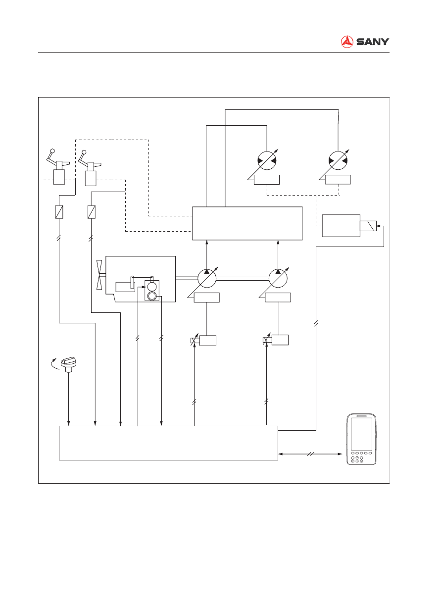
Duo travel speed control

ZX215-1002203

M

P

F

Hi

Lo

F1

ESC

Enter

F2

F3

F4

F5

Regulator

Travel motor

Main valve

Travel Speed
solenoid valve

L. Travel pressure sensor

R. Travel pressure sensor

Regulator

Main pump

Engine

Governor
motor

Servo

Servo

Fuel injection
pump

Controller

Monitor

(CAN


bus)

(Control signal)

(Control signal)

(Throttle position feedback signal)

(Motor drive signal)

Fuel control dial

Structure and Function

SY215C

LC

4-189

Function


Control travel mode.

Operating condition


When Hi speed travel mode on the monitor 
is enabled.

Remark: 

When one side of the tracks is lifted off the 
ground by the work equipment and rotating, 
pressure at one side of the pump increases, 
which makes the lifted track rotate very fast. 
When the machine is traveling under Hi speed 
mode, even if work equipment is being op-
erated (work equipment pressure sensor is 
switched ON), travel mode remains in Hi travel 
mode. 

Operation


When the travel mode is set at LO speed, 
the swash plate angle of the travel motor is 
the largest, and travel speed is low.


When the controller receives the signal 
from the travel pressure sensor under the 
conditions below, it activates the solenoid 
valve. Then, the solenoid valve conducts 
pilot pressure oil to the swash plate angle 
control valve of the travel motor, and re-
duces the swash plate angle to increase 
travel speed. 

Structure and Function

SY215C

LC

4-190

4.9.7  

Engine preheating/overheating alarm 

ZX215-1002204

M

P

F

Hi

Lo

Heat

F1

ESC

Enter

F2

F3

F4

F5

Main valve

Start switch

Preheat s/w

Preheat relay

Coolant

tempe

sensor

Governor motor

Servo

Main
pump

Controller

Servo

Monitor

(CAN


bus)

Engine

(Control signal)

(Control signal)

(Motor drive signal)

(Throttle position feedback signal)

Fuel control dial

Structure and Function

SY215C

LC

4-191

Function


Preheating control

Operation


This function shall be used in combination 
with the preheating switch located on the 
right armrest. Turn the engine start key 
counterclockwise to the HEAT position and 
hold on, the engine will start preheating. 
When released, the key will return to the 
OFF position automatically and preheating 
stops.

Operating condition


Power ON. Start key set at the HEAT posi-
tion.


Preheating switch: ON

4.9.7.1 Engine preheating

Structure and Function

SY215C

LC

4-192

Function


When engine coolant temperature be-
comes excessively high (above 110°C) 
during operation, overheating alarm on the 
monitor display will light up.

Operation


The controller collects signal from the cool-
ant temperature sensor. When coolant 
temperature rises too high, alarming infor-
mation will be generated and transmitted 
to the machine monitor. The alarm lamp on 
the display lights up when the monitor re-
ceives the signal.

Operating condition


Power ON.


Coolant temperature above 110°C.

4.9.7.2  Engine overheating alarm

Function


The engine controller collects signal from 
the engine oil pressure sensor. When en-
gine speed exceeds 600 rpm, if oil pres-
sure is too low, alarming information will be 
generated and transmitted to the machine 
monitor. The alarm indicator lights up when 
the monitor receives the signal. 

4.9.8  Engine oil under

pressure alarm

Structure and Function

SY215C

LC

4-193

4.9.9  

Auto deceleration/acceleration control

ZX215-1002205

F1

ESC

Enter

F2

F3

F4

F5

(

Throttle signal)

Engine
throttle
controller

Control lever signal

Controller

Monitor

(CAN


bus)

Engine

Fuel control dial

(

Motor drive signal)

(

Potentiometer signal)

Right joystick

Boom

Bucket

DOWN

UP

IN

OUT

Left joystick

Swing

Arm

R

L

CURL

DUMP

L.Travel

Travel lever

R.Travel

Forward Reverse

Forward

Reverse

Structure and Function

SY215C

LC

4-194

Operation


Three seconds after all control levers are 
neutralized, engine speed will drop to the 

fi

 rst deceleration level about 100 rpm lower 

than the set speed. After another 3 sec-
onds engine speed enters low speed (1350 
rpm) to reduce the loss of the hydraulic 
system and engine wear, and reduce fuel 
consumption and noise. When the control 
lever is operated again, the engine  speed 
rises instantly to the previous level.


If any control lever is operated while the 
engine speed is kept at decelerated level, 
engine speed will rise instantly to the level 
set by the fuel control dial.

Function


If all the control levers are neutralized, en-
gine speed will drop to the medium level 
automatically to reduce fuel consumption 
and noise.


If any of the levers is operated, the engine 
speed rises to the set level instantly.

ZX215-1002206

3s

(1350rpm)

Drop 

100rpm

Control lever

Operated

Unoperated

Operated

Set rpm


Time (second)

less than 2 S

Deceleration

Less than 1 S

Speed (rpm)

Structure and Function

SY215C

LC

4-195

4.9.10  

Engine speed calibration function

ZX215-1002207

SW

LED

7

LED

LED

MEMORYON

DOWN

UP

RPW

H

S

L

A/I

H

S

L

A/I

SW

M

P

F

Hi

Lo

F1

ESC

Enter

F2

F3

F4

F5

R. Travel signal

L. Travel signal

Boom UP signal

Boom DOWN signal

Arm IN signal

Arm OUT signal

Bucket DIG signal

Bucket DUMP signal

Swing signal

Calibtator

(CAN


bus)

Controller

Monitor

Fuel control dial

(Engine speed signaL)

(Control signaL)

(Control signaL)

(Motor drive signaL)

(Throttle position feedback signaL)

Engine

Speed

sensor

Main pump

Main valve

Bucket confluence

Swing pripority

Pressure sensor

Servo

Servo

Pressure sensor

Fuel injection
pump

Governor
motor

Structure and Function

SY215C

LC

4-196

Function


Set the maximum engine speed under 
each working mode. This set speed is the 
standard to control engine speed. 

Operation


Calibrating procedure for positive 

fl

 ow  ex-

cavators.

1)  H, S, L maximum speed calibration, and A/

I speed calibration.

2)  Turn the dial on the calibrator counter-

clockwise to the end

3) Power OFF

4)  Set the calibrator to "Monitor mode", power 

on and check the result.

Remark: 

Memory SW up: Calibration mode; 

Memory SW down: Monitor mode

Structure and Function

SY215C

LC

4-197

4.9.11  

System Components

4.9.11.1  Pump pressure sensor

Operation


The relationship between the pressure ap-
plied to sensors (P) and output voltage (E) 
is shown in the 

fi

 gure on the right.

ZX215-1002208

A

Z

B

C

Terminal A

Terminal B

Terminal C

Pressure connector

Body

Connector

Connection diagram

No.

Signal name

Z direction

Grounding

Output

ZX215-1002209

.

.

3

30

2

20

1

10

0

0

(V)

5
5

50

5

4

40

4

(MPa)

Sensor output voltage (E)

Oil pressure (P)

Structure and Function

SY215C

LC

4-198

4.9.11.2  Pilot pressure sensor

Operation


The relationship between the pressure ap-
plied to sensors (P) and output voltage (E) 
is shown in the 

fi

 gure on the right.

ZX215-1002208

A

Z

B

C

Terminal A

Terminal B

Terminal C

Pressure connector

Body

Connector

Connection diagram

No.

Signal name

Z direction

Grounding

Output

ZX215-1002210

.

.

3

3

2

2

1

1

0

0

(V)

5
5

5

5

4

4

4

(MPa)

Sensor output voltage (E)

Oil pressure (P)

Structure and Function

SY215C

LC

4-199

4.9.11.3  Engine speed sensor

Operation


Measure the resistance between terminal 
1 and terminal 2 when it is in service.

Standard value (@25°C)

2.3±0.2 k

Ω


If the measured value exceeds the stan-
dard value, replace the sensor. 


If the engine speed sensor is not tight-
ened to the specified torque, the sen-
sor may send out no signals. Tighten 
the engine speed sensor to the speci-
fi ed torque.

Function


The engine revolution sensor is installed to 
the ring gear of the engine 

fl

 ywheel. It elec-

trically calculates the number of the gear 
teeth which pass in front of it and transmits 
the result to the engine controller.

ZX215-1002211

1

2

CAUTION

Structure and Function

SY215C

LC

4-200

4.9.11.4  Coolant temperature sensor

1- Sensor
2- Connector

Function


The output resistance of the engine cool-
ant temperature sensor changes with the 
coolant temperature. The controller collects 
and processes coolant temperature signals 
and works out the coolant temperature.

Standard 

value

50°C

80

Ω

 (Ref.)

60°C

56.3

Ω

80°C

29.5±10

Ω

100°C

16.5

Ω

106°C

14.3±0.5

Ω

120°C

10

Ω

(Ref.)

Specifi cations

ZX215-1002212

1

2

Structure and Function

SY215C

LC

4-201

ZX215-1002246

1

2

3

4

4.9.11.5 Fuel sensor

1- Float
2- Lever

3- Casing
4- Coupler

Structure and Function

SY215C

LC

4-202

4.9.11.6  Oil pressure switch

1- O-ring
2- Sensor
3- Connector

Function


The oil pressure switch is installed on the 
outlet circuit of the oil filter. It detects oil 
pressure and transmits warning signals to 
the controller.

Specifi cations


Type of contact: Normally closed


Operating pressure: 1.9kg

ZX215-1002214

1

2

3

Pressure

Electrical
diagram

Load

Structure and Function

SY215C

LC

4-203

4.10  

Monitoring System

ZX215-1002215

Sany Hydraulic Excavator

S

10

S

0000

h

00

m

12

00:00:00

00/00/00

A

B

C

F1

ESC

Enter

F2

F3

F4

F5

CAN signal

Sensor

Engine
controller

Power source

Battery

Machine monitor

n/min

AUTO


The state of the machine is monitored 
by the sensors mounted on the machine 
components. The controller processes the 
signals and transmits the signals to the 
monitor display, informing the operator of 
the machine condition. 


Information on the monitor display includes 
primarily:

1.  Alert information when a machine fault is 

detected.

2.  Operating condition (coolant temperature, 

fuel level, etc. )


The machine control system can be oper-
ated using the switches and keys on the 
monitor panel. 


Content      ..     16      17      18      19     ..