SANY Crawler Hydraulic Excavator SY215CLC (CUMMINS QSB6.7 engine). Shop Manual - page 19
 

  Index      Manuals     SANY Crawler Hydraulic Excavator SY215CLC (CUMMINS QSB6.7 engine). Shop Manual


Search            copyright infringement  


Content      ..     17      18      19      20     ..


SANY Crawler Hydraulic Excavator SY215CLC (CUMMINS QSB6.7 engine). Shop Manual - page 19


Structure and Function

SY215C

LC

4-204

4.10.1  

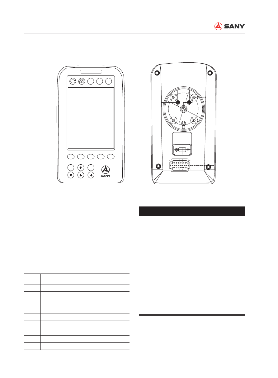
Machine monitor

Outline


The monitor displays various kinds of items 
and is used by the operator to select a 
working mode.


The monitor has a CPU which processes, 
displays, and outputs information.


The monitor has an LCD (Liquid Crystal 
Display) screen. 

Input and output signals

No.

Signal name

Input/output

1

Digital input A

Input

3

CAN high

4

CAN low

7

Digital input B

8

Trigger power source (24V)

9

Power source (24V)

10

Grounding 

11

Digital input C

12

Grounding 


The LCD may have black spots (which 
do not light up) or bright spots (which 
stay on). Products having 10 or less 
black or bright spots conform to the 
product specification; such condition 
is quite normal.


Continuous operation of the monitor 
may cause the LCD to display bright 
blue spots on a black background; it is 
quite normal.


When the monitor is turned on, blinking 
strips may appear on the LCD screen. 
This is normal. 

ZX215-1002216

1

12

6

7

A

B

C

F1

ESC

Enter

F2

F3

F4

F5

NOTICE

Structure and Function

SY215C

LC

4-205

4.10.2  

Monitor functions

When the engine start switch is turned to ON 
position, the monitoring system is energized. 

The monitor screen displays the home page.

XP21511027H

F1

F2

F3

F4

F5

ESC

Enter

C

H

E

F

12

36

h

25

m

2010/07/27
1 5 : 3 2 : 4 8

A

B

C

SANY Hydraulic Excavator

n/min

5

S

AUTO

S

Indicators

Screen display

Keys

Alarm lamp

Signal indicators

Page heading

Home page

Function icons

Function keys

Operation keys

Structure and Function

SY215C

LC

4-206

Indicators

1. Alarm lamp


When a fault occurs on the machine and 
is detected by the monitor, the alarm lamp 
lights up, informing the operator to take 
trouble shooting measures.

2.   Signal indicators


The signal indicators include power indica-
tor, CAN indicator and backup indicators 
for the user to de

fi

 ne. 

Screen display

All screen pages are displayed on the LCD. 
Different page heading, page content, param-
eters, time, and function icons are displayed 
on the screen according to different selected 
entries. The user is allowed to switch between 
different entries, and adjust data and param-
eters. 

1.  Working mode (H, S, L and B)

2.  Engine speed level (1~11)

3.  Coolant temperature (°C)

4.  Fuel level (%)

5.  Failure code (Refreshed every 2 seconds)

6.  Total service hours (××h××m)

7. Date (Y/M/D)

8.  System clock (H:M:S)

XP21511028H

A

B

C

2

1

SANY Hydraulic Excavator

C

H

E

F

12

36

h

25

m

2010/07/27
1 5 : 3 2 : 4 8

XP21511029H

1

3

4

6

2

5

7

8

SANY Hydraulic Excavator

AUTO

n/min

5

S

S

Structure and Function

SY215C

LC

4-207

Monitor keys

Keys on the monitor include function keys and 
operation keys. 

Function keys


Functions of keys F1 to F5 are indicated 
respectively by the icons above them on 
the screen display.


When the icon above a certain function 
key changes, the function of this key will 
change accordingly.


When there is no icon above a function 
key, this key is disabled.

Function keys

Icon

Function

Monitor display

F1

S

Working mode selection

H

S

L

B

F2

n/min

AUTO

Auto idle mode switch

AUTO

→ →

AUTO

F3

High/Low travel speed switch


F4

Enter a selected item/Set up an item

Same as  Enter

F5

Enter information menu

------

Return to previous page

Same as  ESC

Each time the machine is energized, default 
display on the monitor screen is as follows:


Working mode: H


Auto idle switch: Auto idle


Travel speed switch: Low speed

F1

F2

F3

F4

F5

ESC

Enter

1

2

AUTO

n/min

S

Structure and Function

SY215C

LC

4-208

Auto deceleration switch


Auto idle mode is the default mode. When 
the engine is under auto idle mode, it will 
enter idling state automatically if no control 
levers are operated for 5 consecutive sec-
onds to save fuel and reduce noise. En-
gine speed is regulated by the controller. 


When the engine is idling, engine speed 
returns automatically to previous level set 
by the fuel control dial once the controller 
detects the action from any control lever or 
the adjustment of fuel control dial.


Auto idle mode is disabled when the ma-
chine is working under L mode.

Operation keys

Operation keys

Function

Enter

Enter/Con

fi

 rm

ESC

Return to previous page

Select item on upper side (Selects bottom item after top item)

Select item on lower side (Selects top item after bottom item)

Select item on left side (Selects right end item after left end item)

Select item on right side (Selects left end item after right end item)

Structure and Function

SY215C

LC

4-209

Screen display

1.  Working mode indicator (H, S, L and B)

2.  Coolant temperature (°C)

3.  Fuel level (%)

4.  Total service hours (h/m)

5.  Working mode selection button. 

6.  Switch on/off auto idle: 

AUTO

→ →

AUTO

…… 

7. Travel speed: 

……

8.  Go to Failure codes.

9.  Main menu icon.

10. System time (h:m:s)

11. Failure code. Refreshed every 2 seconds.

12. Engine speed level (1~11)

Keypad input


Press F1 to switch between four working 
modes (H, S, L and B).

4.10.3  

Screen display and operation

4.10.3.1 Initializing page

When the start switch is turned to the ON po-
sition, the initializing page will be displayed on 
the monitor screen. 

When initializing process is over after about 2 
seconds, the screen displays the Home page.

4.10.3.2 Home page

Function

This is the normal operation display. Items 
displayed on the home page include, working 
mode, engine gear level, coolant temperature, 
total service hours, system time and alarm in-
dicator. Working conditions of the machine can 
be set up on this page.

XP21511031H

C

H

E

F

12

36

h

25

m

1 5 : 3 2 : 4 8

9

4

3

2

1

12

11

8

7

6

5

10

SANY Hydraulic Excavator

AUTO

n/min

S

5

S

Sany Heavy Machinery

Quality Changes the World

n/min

Structure and Function

SY215C

LC

4-210

Screen display

1.  A 5-digit password. Each digit is indicated 

by an asterisk (*) standing for a value 
from 0 to 9. A numeral appears at the digit 
where the cursor is located while the other 
four digits are in asterisk. 

2.  Change the value of the digit where the 

cursor is located. 

3.  Move the cursor. 

4.  Check the password and go to Main Menu 

if the password is correct, or tell the user to 
enter the correct password, if the password 
is wrong.

5.  Return to the home page. 

Keypad input


Press F1 or 

 and 

 to change the 

value of the digit where the cursor is locat-
ed.


Press F2 or 

 and 

 to move the 

cursor.


Press F3 or 

Enter

 to check the validity of 

the password and go to Main Menu if it is 
correct.


Press F5 or 

ESC

 to return to the home 

page.

4.10.3.3 System Information

Function

Enter the password before accessing the sys-
tem information page. 

XP21511004

信 息 查 询

* * * * *

1

5

4

3

2

System Information

Please enter password:


Press F2 to select auto idle or full speed.


Press F3 to select high or low travel speed.


When a failure alarm occurs, press F4 to 
go to Failure Codes. 


Press F5 to go to System Information. 

Structure and Function

SY215C

LC

4-211

4.10.3.4 Main Menu

Function

A list of system functions that can be selected 
to access different options. 

Screen display

1.  System information menu. 

2.  Scroll up and down to select an entry on 

the menu. 

3.  Access the selected entry. 

4.  Go to System Setup password entry page.

5.  Return to the home page. 

6.  Brief description of the selected entry.


Operating parameters of the engine, 
main pump and main valve.


Failure codes.


Throttle help information.


System language selection.


System clock adjustment


Unit display setting.

Keypad input


Press F1 or 

 and 

 to scroll up 

and down and select an entry in the list.


Press F2 or 

Enter

 to access the selected 

entry.


Press F4 to go to System Setup password 
entry page.


Press F5 or 

ESC

 to return to the home 

page.

XP21511032H

1

System Clock Calibration

Failure Information

Throttle Help Information
Language Selection

Engine, pump and valve parameters

Unit Selection
Working mode selection

Running Information

5

4

3

2

6

Main  Menu

Structure and Function

SY215C

LC

4-212

4.10.3.5 Engine Signals

Function

Display the operating parameter of the engine. 

Screen display

1.  Real-time display of engine signal collected 

by the controller. 

2.  Move to the next page Throttle Signals. 

3.  Return to Main Menu.

Keypad input


Press F1 to go to Throttle Signals.


Press F5 or 

ESC

 to return to Main Menu.


Press 

 to go to Main Valve Signals.


Press 

 to go to Throttle Signals.

XP21511006H

1

3

2

Engine Signals

Coolant Temp °C

Fuel Level  %

Engine Oil Press kPa

XP21511007H

1

3

2

Throttle Signals

Throttle Gear     N:         12

Engine Speed    rpm:     1234

Gear Position     V:        1.23

Throttle Position  V:       1.23

4.10.3.6 Throttle Signals

Function

Display engine throttle signal information. 

Screen display

1.  Real-time display of engine throttle signal 

collected by the controller. 

2.  Move to the next page Pilot Pressure Sig-

nals - 1. 

3.  Return to Main Menu.

Keypad input


Press F1 to go to Pilot Pressure Signals - 1.


Press F5 or 

ESC

 to return to Main Menu.


Press 

 to go to Engine Signals.


Press 

 to go to Pilot Pressure Signals 

- 1.

Structure and Function

SY215C

LC

4-213

XP21511008H

1

3

2

Pilot Press Signals -1

Boom UP         kg:     123.4

Boom DOWN   kg:     123.4

Arm IN             kg:     123.4

Arm OUT         kg:     123.4

XP21511009H

1

3

2

Pilot Press Signals -2

Bucket DIG      kg:     123.4

Bucket DUMP  kg:     123.4

Swing              kg:     123.4

Travel Left       kg:     123.4

Travel Right    kg:     123.4  

4.10.3.7  Pilot Pressure Signal - 1

Function

Display hydraulic system pilot pressure signals

Screen display

1.  Real-time display of pilot pressure signal 

collected by the controller. 

2.  Move to the next page Pilot Pressure Sig-

nals - 2. 

3.  Return to Main Menu.

Keypad input


Press F1 to go to Pilot Pressure Signals - 2.


Press F5 or 

ESC

 to return to Main Menu.


Press 

 to go to Throttle Signals.


Press 

 to go to Pilot Pressure Signals 

- 2.

4.10.3.8  Pilot Pressure Signal - 2

Function

Display hydraulic system pilot pressure signals

Screen display

1.  Real-time display of pilot pressure signal 

collected by the controller. 

2.  Move to the next page Main Pump Signals. 

3.  Return to Main Menu.

Keypad input


Press F1 to go to Main Pump Signals.


Press F5 or 

ESC

 to return to Main Menu.


Press 

 to go to Pilot Pressure Signals 

- 2.


Press 

 to go to Main Pump Signals.

Structure and Function

SY215C

LC

4-214

4.10.3.9  Main Pump Signals

Function

Display main pump signal of the hydraulic sys-
tem.

Screen display

1.  Real-time display of main pump signal col-

lected by the controller. 

2.  Move to the next page Main Valve Signals. 

3.  Return to Main Menu.

Keypad input


Press F1 to go to Main Valve Signals.


Press F5 or 

ESC

 to return to Main Menu.


Press 

 to go to Pilot Pressure Signals 

- 2.


Press 

 to go to Main Valve Signals.

4.10.3.10  Main Valve Signals

Function

Display main valve signal information. 

Screen display

1.  Real-time display of main valve signal. 

When the output switches are ON, the indi-
cator turns green. 

2.  Move to the next page Engine Signals. 

3.  Return to Main Menu.

Keypad input


Press F1 to go to Engine Signals.


Press F5 or 

ESC

 to return to Main Menu


Press 

 to go to Main Pump Signals.


Press 

 to go to Engine Signals.

XP21511010H

1

3

2

Main Pump Signals

Pump 1 Main Press  kg:     123.4

Pump 2 Main Press  kg:     123.4

Prop Vavle 1 Current  mA:     123.4

Prop Vavle 2 Current  mA:     123.4

XP21511011H

1

3

2

Main Valve Signals

Bucket Confl Valve

Swing Priority Valve

Boom Priority Valve

High/Low Speed Shift

Structure and Function

SY215C

LC

4-215

4.10.3.11 Fault Information

Function

Display fault code and fault information. 

Screen display

1. Fault code. 

2.  Return to Main Menu.

Keypad input


Press F5 or 

ESC

 to return to Main Menu.

4.10.3.12  Throttle Help Information

Function

Throttle installation assistance. 

Screen display

1.  Real-time display of detected value. 

2. Working mode.

3.  Auto-idle and full speed.

4.  High and low travel speed.

5.  Return to Main Menu.

Keypad input


Press F1 to switch between H, S, L and B 
mode.


Press F2 to switch between auto-idle mode 
and full speed.


Press F3 to switch between high and low 
travel speed.


Press F5 or 

ESC

 to return to Main Menu.

XP21511012H

2

1

Failure Codes

CURRENT FAULT CODE: 

11 Controller failure
12 Motor current/connection abnormal
13 Motor operation paused
14 Motor working range improper
15 Power supply volt over 36V
16 Internal temp of controller abnormal
17 Sensor power supply abnormal
18 Abnormal communication with monitor
19 Backup battery voltage low
20 F. pump output pressure abnormal
21 R. pump output pressure abnormal
22 Arm-in pilot pressure abnormal
23 Arm-out pilot pressure abnormal
24 Boom-up pilot pressure abnormal
25 Boom-down pilot pressure abnormal
26 Bucket-dig pilot pressure abnormal
27 Bucket-dump pilot pressure abnormal

28 Swing pilot pressure abnormal
29 Left travel pilot pressure abnormal
30 Right travel pilot pressure abnormal
31 Potentiometer(for motor setup) abnormal
32 Motor built-in potentiometer abnormal
33 Backup pilot pressure abnormal
37 Oil temp sensor volt abnormal
39 Coolant temp resistance abnormal
40 Fuel gauge abnormal
41 Engine speed low
50 F. pump current abnormal
51 R. pump current abnormal
52 Swing priority current abnormal
53 Bucket confluence current abnormal
54 Boom priority 1 current abnormal
55 Boom priority 2 current abnormal
60 Speed shift abnormal

XP21511036H

1

5

3

4

2

Current Gear    N:     11 

Engine Speed  rpm:     1200

Gear Position     V:       1.23

Throttle Position  V:     1.23

Throttle Help Info

AUTO

n/min

H

Structure and Function

SY215C

LC

4-216

4.10.3.13 Language Selection

Function

Select system language. 

Screen display

1.  List of system languages.

2. Español

3. English

4.  Return to Main Menu.

Keypad input


Press F2 to select Español.


Press F3 to select English.


Press F5 or 

ESC

 to return to Main Menu.

4.10.3.14  System Clock Calibration

Function

Adjust system time. 

Screen display

1. Current time. 

2. Adjusted time. 

3.  Save adjusted time.

4.  Return to Main Menu.

Keypad input


Press F1 or 

Enter

 to con

fi

 rm and save ad-

justed time.


Press F5 or 

ESC

 to return to Main Menu.

Remark:


When F1 or 

Enter

 is pressed, “Adjustment 

fi

 nished” is displayed on the bottom.


System time can not be adjusted once 
again until the system is re-energized. 

XP21511015H

1

2

4

3

Current Time

1234·12·12   12

12

12

Calibration Time

1234·12·12   12

12

12

Use [

][

][

][

] to set up system clock.

Sys Clock Calibration

XP21511033H

1

4

2

3

E n g

E s p

English

Español

Language Selection

Structure and Function

SY215C

LC

4-217

1

4

2

3

XP21511034H

Unit Display Setting

Imperial System

Metric System

4.10.3.15  Unit Display Setup

Function

Set up system unit display. 

Screen display

1.  Metric and Imperial unit.

2.  Switch between Metric and English unit.

3. Con

fi

 rm unit selection.

4.  Return to Main Menu

Keypad input


Press F1 to switch between Metric and Im-
perial unit system.


Press F2 or 

Enter

 to con

fi

 rm unit selection.


Press F5 or 

ESC

 to return to Main Menu.

4.10.3.16  Working Mode Selection

Function

Set default working mode to H, S or L. 

Screen display

1.  Current default working mode.

2.  Adjusted default working mode.

3.  Switch between H, S, L and B mode.

4. Con

fi

 rm default working mode selection.

5.  Return to System Setup

Keypad input


Press F1 to switch between H, S, L and H.


Press F2 or 

Enter

 to con

fi

 rm default work-

ing mode adjustment.


Press F5 or 

ESC

 to return to System Set-

up.

1

5

3

4

2

Use F1 to select

XP21511035H

H

Working Mode Selection

Current default mode:  

Adjusted default mode:

Structure and Function

SY215C

LC

4-218

Screen display

1.  A 5-digit password. Each digit is indicated 

by an asterisk (*) standing for a value 
from 0 to 9. A numeral appears at the digit 
where the cursor is located while the other 
four digits are in asterisk. 

2.  Change the value of the digit where the 

cursor is located. 

3.  Move the cursor. 

4.  Check the password and go to System 

Setup if the password is correct, or tell the 
user to enter the correct password, if the 
password is wrong.

5.  Return to Main Menu. 

Keypad input


Press F1 or 

 and 

 to change the 

value of the digit where the cursor is locat-
ed.


Press F2 or 

 and 

 to move the 

cursor.


Press F3 or 

Enter

 to check the validity of 

the password and go to System Setup if it 
is correct.


Press F5 or 

ESC

 to return to Main Menu.

XP21511016H

5

4

3

2

1

* * * * *

System Setup

Please enter password:

Remark:


Password of this page is only authorized to 
service workers.

4.10.3.17  System Setup Password Entry

Function

Enter the password before accessing the sys-
tem setup page.

Structure and Function

SY215C

LC

4-219

4.10.3.18  System Setup Menu

Function

Set up machine con

fi

 guration. 

Screen display

1.  System setup menu. 

2.  Scroll up and down to select an entry on 

the menu. 

3.  Access the selected entry. 

4.  Return to System Setup. 

Keypad input


Press F1 or 

 and 

 to scroll up 

and down and select an entry in the list.


Press F2 or 

Enter

 to access the selected 

entry.


Press F5 or 

ESC

 to return to Main Menu.

XP21511017H

4

3

2

1

System Setup

Machine Configuration

Service Hour Calibration

Machine Config Calibration

Hydraulic Oil Temp


Content      ..     17      18      19      20     ..