SANY SRT95C Off-Highway Truck. Service Manual - page 19
 

  Index      Manuals     SANY SRT95C Off-Highway Truck. Service Manual


Search            copyright infringement  


Content      ..     17      18      19      20     ..


SANY SRT95C Off-Highway Truck. Service Manual - page 19


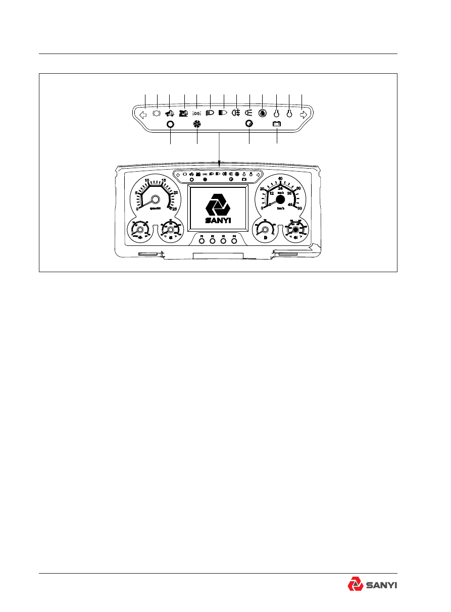
Indicator

1. Left steering Indicator (Green) - Flashes 
when the left indicator lights are operating. 
2. Parking Brake (Red)-Illuminates when the 
parking brake is applied.
3. Body up (Yellow) - Illuminates to indicate 
that the body is NOT resting on the chassis. 
Never move the machine until this light goes 
OUT.
4. Retarder Indicator (Yellow) - Illuminates 
when the retarder is applied.
5. Side marker lamp (Yellow) - Such lamp will 
be on when side marker lamp starts to work.
6. Dipped beam Indicator (Green)-Illuminates 
when dipped beam head lamps start to work.
7 High beam Indicator (Blue)-Illuminates when 
high beam head lamps start to work.
8. Fog Indicator (Yellow) - Such lamp will be 
on when fog lamps start to work.
9.Rear Indicator (white)-
10. Engine Stop Indicator Red) - When the 
'Stop'  light  comes  on,  the  computer  has 
detected a major malfunction in the engine 

Fig.2

1

2

3

4

5

6

7

8

9 10

11

16

17

P

P

12 13

14

15

Cab Accessories

that requires immediate attention. 
Stop the machine when this light illuminates 
and do not operate until the fault is corrected.
11. Engine Maintenance Indicator ( White) 
-  Indicates  that  the  engine  needs  to  be 
maintained. See Cummins Manual for details 

about specific maintenance items.

12. Engine Warning Indicator (Yellow) - When 
the 'Warning' light comes on, the computer has 
detected a fault in the engine which may result 
in a power loss. The fault should be diagnosed 
and corrected at the earliest opportunity.
13. Right steering Indicator(Green) - Flashes 
when the right indicator lights are operating.
14. Alternator Charging (Red) - Illuminates to 
indicate when the alternator is not charging.
15. Transmission Over speed Indicator (red) 
-  Illuminates  when  the  transmission  ECU 
senses transmission speed above 2350 rev/
min.
16. In-converter Indicator (Green)- Illuminates 
when the transmission is in Torque Converter 
drive. It goes OUT when Lockup is engaged.
17. Check Trans Indicator (Red) - Illuminates 
to  alert  of  a  fault  in  the  transmission  shift 
system or abnormal transmission temperature. 
The light will illuminate when the ignition key 
switch is turned to position '1' to provide a bulb 
and system check and should go off a few 
seconds after the engine is started.

P

6

7

4

3

2

1

5

Fig.3

Cab Accessories

Instrument

1. Tachometer
Driven by CAN bus; it indicates engine speed 
in revolutions per minute. When the pointer 
is located in white area said speed is normal, 
and once the pointer is located in red area 
that speed is too high, should reduce speed 
immediately.
2. Speedometer
Driven  by  CAN  bus;  it  indicates  vehicle 
running speed. When the pointer is located in 
white area said speed is normal, and once the 
pointer is located in red area that speed is too 
high, should reduce speed immediately.
3. Transmission Oil Temperature Gauge
The  pointer  indicates  transmission  oil 
temperature  value.  Such  meter  is  directly 
connected  to  transmission  temperature 
sensor. When the pointer is located in white 
area  said  transmission  oil  temperature  is 
normal, and once the pointer is located in red 
area that transmission oil temperature is too 
high, movement, the buzzer for 10 seconds, 
then shut down automatically. In the electric 
power the same fault buzzer action only once. 
4. Fuel level gauge
The  pointer  indicates  percent  of  full  tank 
a  actual  fuel  level.  Such  meter  is  directly 
connected  to  fuel  level  sensor.  When  the 
pointer is located in white area said fuel level 
is normal, and once the pointer is located in 
red area that fuel level is too low, movement, 
the buzzer for 10 seconds, then shut down 
automatically. In the electric power the same 
fault buzzer action only once. 
5. Display
1. Turn on power supply, start the key switch 

toΙ, the display shows 'sany' boot screen(see 

Fig.3-1), and all of the signal indicators are 
applied, 3 seconds after the display shows 
work interface, the lights go out at the same 
time.
2. Click F2 key to change from work interface 
to system function interface, and the work 

Fig.3-1

Fig.3-2

Fig.3-3

SANY MINING EQUIPMENT

System time setting

Parameters query 


Engine information


Monitoring system  

Controller I/O

Parameters setting

Backlight adjust


Chinese             English 

F1:ESC


F2:Enter


F3:


F4:


Buzzer time setting


Restore password

System Function

SANYI

08-25-2012


15:10:25


Wed

Engine

Transmission 

ENG  HRS

     VEH DIST

XXXXX.X

XXXXXX

h

km

Monitor

SANY Mining Equipment 

Cab Accessories

interface is default (see Fig.3-2).
3. Enter the system function interface, F1 key 

to return, F2 key for confirmation key, the F3 

key to move up, and F4 for down key(see 
Fig.3-3).
4. Under the system function interface, click 
the F3 key or F4 key to choose the function 

and click F2 key to confirm. 

Take  the  case  of  setting  system  time  to 
demonstrate operation method:
Under the system function interface:
a.  Click  F3  key  or  F4  key  to  choose  the 
number of the time;

b. Click F2 key to confirm, then the cursor will 

automatically move to the next number(see 
Fig.3-4);
c. When the cursor to the last digit (the second 
single  digits),  click  F2  key  to  confirm  the 
current changes, and then click F2 key again 
to  end  the  modify  Settings  until  appear  a 
square green claim(see Fig.3-5),
d. Click F1 key to return to the system function 
interface. 
6. Engine Water Temperature Gauge
Driven by CAN bus; it indicates engine coolant 
temperature value. When the pointer is located 
in white area said engine coolant temperature 
is normal, and once the pointer is located in 
red area that engine coolant temperature is too 
high, movement, the buzzer for 10 seconds, 
then shut down automatically. In the electric 
power the same fault buzzer action only once.
7. Engine Oil Pressure Gauge
Driven by CAN bus; it indicates engine oil 
pressure value. When the pointer is located in 
white area said engine oil pressure is normal, 
and once the pointer is located in red area that 
engine oil pressure is too high, movement, 
the buzzer for 10 seconds, then shut down 
automatically. In the electric power the same 
fault buzzer action only once.

Fig.3-4

Fig.3-5

F1:


ESC 


F2:


Enter


F3:


F4:


SANYI

2012Y08M13D  

12H30M25S  

System Time Setting

  SANYI

F1:


ESC   F2:


Enter   F3:


F4:


System Time Setting

2012Y08M13D 

12H30M25S  

Cab Accessories

Fig.4 Switch and Meter

绿

2

-0

1K

1

-0

1F

3

2A

-0

1K

5

1

0

5

9

7

10

-0

1S

2

33

7

30

7

30

A6

-0

1K

8

30

87

-0

1K

8

15

20

23

X

M

1.

11

D

I_

02

08

.3

C

-0

1K

3

-0

1K

4

-0

1K

3

-0

1K

4

-0

1K

5

-0

1K

M

1

87

30

-0

1K

1

01

16

30

A3

-0

1E

1

31

A4

01

40

a

31

A5

01

40

b

-0

1G

3

PE

-0

1G

1

G

N

D

BA

T

G

PE

-0

1G

4

-0

1G

5

31

A1

01

18

-0

1G

2

-0

1K

M

1

B

-0

1H

1

20

23

X

M

1.

5

D

O

_0

1

08

.3

C

15

4

3

1

-0

1S

1

0,

1

M

B

+

G

N

D

-0

1M

1

B

1+

S

M

B

+

G

N

D

-0

1M

2

B

1+

S

01

06

01

11

30

A2

31

A6

01

26

01

25

31

A8

01

15

01

02

01

04

01

09

01

13

01

14

31

A7

01

01

-0

1F

1

12

0A

PE

-0

1Q

1

-0

1F

10

2A

2A

-0

1F

9

30

6

0

A

-0

1F

8

30

A1

01

03

30

A4

30

A5

31

02

.2

H

10

31

A9

B6

-0

1F

7

-0

1F

6

-0

1F

5

2

0

A

01

2

9

A

15

AX

01

28

01

27

15

A

-0

1F

4

X

01

12

01

08

6

0

A

30

6

0

A

31

A

1

1

01

32

01

05

 Engine lubrication 

system

Cab Accessories

01G1-  AC generator

01K1- Generator relay

01KM1- X power contactor

01G2- Battery

01K8- Starter signal relay

01M1- Starter motor

01G3- Battery

01K3- Starter motor relay 1 01M2- Starter motor

01G4- Battery

01K4- Starter motor relay 2 01H1- Room lamp

01G5- Battery

01K5-Body power contactor 01S1- Ignition key switch

01S2- Small lamp switch

Fig.5 Circuit Diagram of Video Monitoring System

04A1—Vedio monitor system
04F6—Vedio monitor system fuse

31D1

0401

10A

-04F6

0409

-04A1

Terminal    box

Control box

11.3F

 Camera

Display

Cab Accessories

Fig.6 Cigar Lighter Circuit Diagram

04E1—Cigar lighter

04F1—Cigar lighter fuse

04X1—Socket

Fig.7 MP3 & Radio Circuit Diagram

04A2—MP3 & radio

04H1—Tweeter

04H2—Woofer

04F2—MP3 & radio fuse

XD1

31D2

-04E1

10A

-04F1

-04X1

0402b

0402a

-04A2

15D2

0405

0404

31D3

-04H1

-04H2

10A

-04F2

0403

Cab Accessories

Fig.8 Circuit Diagram of Air Conditioning System

04F3——Fuse

04E2——Air conditioner system

10

0406

XD2

-04F3

15A

31D4

-04E2

air conditioning system

Cab Accessories

T

-05S2

0506

10E1

A30

A30

12V power supply output

27

Alternator charging indicator

26

5V power supply output

25

In-converter indicator

Engine warming indicator

15

14

Engine maintenance indicator

12

Alarm output

17

Earth

9

Earth

10

7

8

Regular power supply

Power supply

2

1

Left steering indicator

Right steering indicator

Check transmission indicator

Engine stop indicator

Trasmission oil temperature sensor signal

Brake accumulator sensor signal

Steering accumulator sensor signal

Body up indicator

Retarder indicator

11

10

Dipped beam indicator

9

21

29

Fuel level sensor signal

Sensor earth

Inside illuminate

High beam indicator

Transmission overspeed indicator

Transmission overspeed indicator

Rear lamp  indicator

Side marker indicator

Parking  brake  indicator

30

31

32

13/26

14

15

16

25

24

23

27

8

7

6

5

4

3

Green 32 core plug

Blue 32 core plug

03.12B

10

10

06.2B

CANL

07.1

1D

08.3D 06.8C

CANH

06.7C 08.3E 07.1

1D

0504

-05F1

5A

31

06.2H

04.10B

15

0503

5A

-05F2

程序 下载 接口

J1_PIN31

J1_PIN1

1

TX

J1_PIN23(RX)

J1_PIN16

J1_PIN9

J1_PIN24

J1_PIN5

30E1

30

06.2B

02.12B

30

J1_PIN12

J1_PIN35

-05P7

GPS

0501

0505

3A

-05F3

-05S1

Q

CANH

CANL

15

31E1

31

A30

A30

-05P2

CAN shield

Power supply

Regular power supply

Cab Accessories

Fig.9 GPS

05F1——GPS fuse

05P2——Combination instrument

05F2——GPS fuse

05S1——Fuel level sensor

05F3——Combination instrument fuse

05S2——Transmission oil temperature sensor

05P7—— GPS

Fig.10 CAN

2

1

2

1

shield L

H

PE

QST30 ECM

E

D

C

CEC2   ECU

S13

S29

S12

120Ω

120Ω

2023 PLC

XM4.7

XM4.8

XM4.3

Combination

instrument

23

24

GPS

J1_PIN35

J1_PIN12

Engine 9 core

diagnostic

interface

C

D

E

25

Cab Accessories

List of Damageable Elements

Relay and type

1

60190151

DC relay JCC400/1C24 48A

2

60190150 

DC relay JCC200/1C24 48A

Lights and Models

1

A241100000648

Headlight assembly A-1

Dipped beam lamp 

90W,high beam lamp 100W

2

A241100000649

Combined front side marker & direction 

light assembly A-4- LED

5W

3

A241100000650

Combined night direction light 

assembly A-5- LED

5W

4

A241100000645

Reverse lamp assembly A-2

70W

5

A241100000647

Retarder light assembly A-6

21W

6

A241100000646

Fog light A-3

35W

7

60006212

Fog light WE-1

35W

5

A241100000647

Retarder light assembly A-6

21W

6

A241100000646

Fog light A-3

35W

7

60006212

Fog light WE-1

35W

Fuse and Models

Fuse Name

Ampere
(A)

Installation 
location

Names 
in central 
distribution 
box

Names in 
small central 
distribution 
box

Power supply 
terminal

01F1

Alternator fuse

120

Battery box

Battery anode 

switch

01F2

Ignition key switch 

fuse

10A

Central 

distribution box

F17

30

01F3

Room lamp fuse  

2A

Central 

distribution box

F19

125

01F4 AX power supply fuse

15A

Small central 

distribution box

F19

X

01F5

A15 power supply 

fuse

20

Central 

distribution box

F24

15

01F6

30 power supply fuse

60

Battery box

Battery anode 

switch

Cab Accessories

01F7

15 power supply fuse

60

Battery box

Battery anode 

switch

01F8

X power supply fuse

60

Battery box

F4

Battery anode 

switch

02F1

Wiper fuse

10

Central 

distribution box

F18

30

02F3

Dipped beam 1 fuse

20

Central 

distribution box

F12

X

02F4

High beam 1 fuse

20

Central 

distribution box

F14

X

02F5

Washer pump fuse

10

Central 

distribution box

F3

30

02F7

Horn fuse

10

Central 

distribution box

F13

30

02F6

Wiper reset fuse

10

Central 

distribution box

F18

30

03F1

Fog lamp fuse

15

Central 

distribution box

F6

X

03F2

Rear lamp fuse

15

Central 

distribution box

F4

X

04F6

Monitor fuse

10

Small central 

distribution box

F5

15

04F1

Cigar lighter fuse

10

Central 

distribution box

F10

X

04F2

MP3/radio fuse

10

Small central 

distribution box

F8

15

04F3

Air conditioner fuse

15

Small central 

distribution box

F20

X

04F4

Actuator

10

Small central 

distribution box

F8

15

05F1

GPS fuse

5

Small central 

distribution box

F6

15

05F2

GPS fuse

5

Central 

distribution box

F20

30

05F3

Combination 

instrument fuse

3

Central 

distribution box

F27

15

07F1

ECM power supply 

fuse 

10

Central 

distribution box

F21

30

Cab Accessories

08F2

5V power supply fuse

2

Central 

distribution box

F1

5

08F3

12V power supply 

fuse

2

Central 

distribution box

F28

12

09F1

17V power supply 

fuse

10

Small central 

distribution box

F9

15

11F1

ECM reverse and 

neutral position fuse

10

Small central 

distribution box

F5

15

14F1

Float solenoid valve 

fuse

5

Central 

distribution box

F16

X

14F2

Stop solenoid valve 

fuse

5

Small central 

distribution box

F14

X

14F3

Parking solenoid valve 

fuse

5

Small central 

distribution box

F13

X

15F1

Reverse lamp and 

buzzer fuse

10

Central 

distribution box

F8

15

15F2

Brake lamp fuse

10

Central 

distribution box

F9

15

15F3

Retarder linear 

actuator fuse

10

Central 

distribution box

F11

15

15F4

Retarder lamp fuse

5

Central 

distribution box

F5

15

09F2

Dipped beam 2 fuse

20

Central 

distribution box

F23

X

09F3

Dipped beam 3 fuse

20

Central 

distribution box

F25

X

09F4

High beam 2 fuse

20

Central 

distribution box

F15

X

09F5

High beam 3 fuse

20

Central 

distribution box

F26

X

14F4

Hoist proportional 

solenoid valve fuse

5

Small central 

distribution box

F1 

2023

14F5

Drop proportional 

solenoid valve fuse

5

Small central 

distribution box

F2

2023

14F6

Retarder solenoid 

valve fuse

5

Small central 

distribution box

F3

2023

Cab Accessories

Fuse and Models

F1

08F2

5V power supply fuse

2A

F3

02F5

Washer pump relay fuse

10A

F4

02F2

Front fog lamp relay fuse

15A

F5

15F4

Retarder lamp relay fuse

15A

F6

03F1

Back fog lamp relay

15A

F8

15F1

Reverse lamp fuse

10A

F10

04F1

Cigar lighter fuse

10A

F11

15F3

Retarder linear actuator fuse

10A

F12

02F3

Dipped beam 1 fuse

20A

F13

02F7

Horn fuse

10A

F14

02F4

High beam 1 fuse

20A

F15

09F1

High beam 2 fuse

20A

F16

14F1

Float solenoid valve fuse

10A

F17

01F2

Ignition key switch fuse

10A

F18

02F1

Wiper fuse

10A

F19

01F3

Room lamp fuse

10A

F20

05F1

GPS fuse

5A

F21

07F1

ECM power supply fuse

15A

F22

02F2

30 power supply fuse

20A

F24

01F5

15 power supply fuse

20A

F25

09F4

Dipped beam 3 fuse

20A

F27

05F2

Combination instrument fuse

3A

F28

08F3

12 power supply fuse

2A

F7

04F5

Rear lamp relay fuse

15A

F9

15F2

Brake lamp fuse

10A

F23

09F2

Dipped beam 2 fuse

20A

F26

09F5

High beam 3 fuse

20A

Cab Accessories

9    HYDRAULIC  STEERING 

PIPELINE OF OPERATOR’S 

CAB

9.1 Steering Control Unit 

Overview

The steering control unit is connected to the 
the steering valve and it controls the hydraulic 

flow direction of steering system.

There are four ports on the unit:
’P’ - In pressure form accumulator
’T’ - Hydraulic oil that goes through this port 
back to tank
’R’ - Hydraulic control oil that goes through this 
port to the cylinder which drives machine turn 
right 
’L’ - Hydraulic control oil that goes through this 
port to the cylinder which drives machine turn 
left
The action of steering wheel is transmitted 
to the bush and driving shaft via the steering 

shaft. In addition, the driving shaft is fixed and 

connected onto the bush by the mid-position 
pin. The rotation of driving shaft leads to the 
rotation of gear in the housing.
When the gear rotates, the oil is pressurized 

to flow to the port of steering cylinder via the 

spool and the bush.
There  is  a  way  to  the  bush  from  spool.  It 
rotates inside the bush and provides the oil 
direction control.

The rated flow of steering control unit at 7MPa 

(1000psi) is 1.0L/S.

Operation

When  the  operator  operates  the  steering 
wheel to left or right by a certain angle, the 
steering action is transmitted to the spool via 
the steering column. When it is rotated by the 
minimum angle of 2.5 degrees, the port of 
valve spool starts to be aligned with the port of 
bush. When the steering wheel is rotated by 
the maximum angle of 10 degrees, the ports 
are completely aligned to allow the maximum 

1

2

Fig.9.1-1 Assembly drawing 

1. Screw

2. Steering control unit 

R

L

T

P

Fig.9.1-2  Hydraulic  schematic  diagram  of 
Steering control unit 

Hydraulic Steering Pipeline Of Operator’s Cab

flow to pass. After the 10-degree rotation is 
performed in any direction, the valve spool 
and bush connected via the mid-position pin 
rotates as one assembly.
The pressure oil via P port to the bushing and 
spool to drives steering control unit works and 
provides pressure oil to the R port for makes 
truck turn right. If hydraulic oil through L port 
to the cylinder, then the truck will turn left.  
hydraulic oil will go back to tank via T port of 
the steering control unit when the cylinder 
moves.
The spool will goes back to the home position 
by tension of mid-spring after the steering 
force is released. In such a way, the oil port is 
disengaged from the original alignment state 

so that the oil liquid of pump doesn’t flow into 

the  steering  cylinder  any  more. The  truck 
won’t make the steering any more and it will 
keep the current turning radius until the spool 
is rotated for its limit of minimum 2.5-degree 
angle.
For the left steering, as the steering column 

rotates, the oil flow from the accumulator save 

block (See the steering valve group in this 
chapter) is input into the steering control unit  
meter via the bushing and the valve spool and 
it enters into the piston cavity of right steering 
cylinder and the piston cavity of left steering 
cylinder from the port ‘L’ of Steering control 

unit. The discharged oil flows into the port ‘R’ 

of Steering control unit  from the other end of 
steering cylinder and it is discharged into the 
oil tank from the port ‘T’.
For the right steering: As the steering column 
rotates,  the  oil  flow  from  the  accumulator 
save block (See the steering valve group in 
this chapter) is input into the steering control 
unit  meter via the bush and valve spool and it 

flows out of the port ‘R’ of Steering control unit  

and enters into the piston cavity of left steering 
cylinder and the piston cavity of right steering 
cylinder. The discharged oil flows out via the 
port ‘L’ of steering valve from the other end 

Hydraulic Steering Pipeline Of Operator’s Cab


Content      ..     17      18      19      20     ..