SANY SRT95C Off-Highway Truck. Service Manual - page 18
 

  Index      Manuals     SANY SRT95C Off-Highway Truck. Service Manual


Search            copyright infringement  


Content      ..     16      17      18      19     ..


SANY SRT95C Off-Highway Truck. Service Manual - page 18


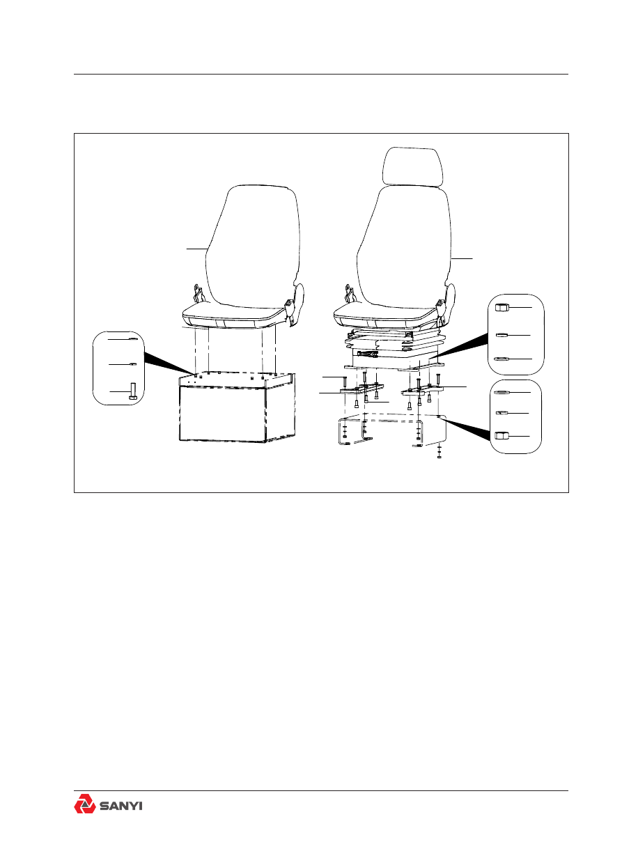
Fig.4 Seat Mounting Assembly

1. Mechanic suspension seat

6. Bolt

2. Nut

7. Right connecting board

3.Washer

8. Bolt

4. Washer

9. Bolt

5. Left connecting board

10. Passenger seat

8.1.2 Seat mounting assembly

Cab Accessories

5

3

7

9

3

1

6

4

3

2

8

2

4

4

10

Overview

See Fig.4 for the numbers in brackets.
Fix driver’s seat onto the cab’s bottom board 
with bolt (8), washer (3

4) and nut (2). The 

seat  assembly  is  mounted  onto  the  seat 
support  with  a  resilient  cushion  and  back 
cushion; and the seat frame is mounted onto 
the bracket of driver’s seat in an air-borne 
manner. One adjustable 2-point type safety 

belt is configured and it is fixed onto the seat 

assembly.
Caution: This seat can automatically adjust 
the  rigidity  of  suspension  mechanism  in 
accordance with the weight of driver through 
the sensor on the seat so as to adapt seat to 
the weight of driver.
1. The caster angle of seat back is controlled 
through the backrest adjusting handle and can 
be adjusted at the driver’s will.
2. The seat can be raised by 30mm when you 
hear a "click" sound, and another 30mm at 
the second "click". Move the backrest to an 
optimum position at where operation can be 
easily conducted, and release the handle.
3. Pull up the seat can adjust height, there are 
three  levels(low

middle

high),  when  the 

seat is on high level, if pull up the seat, it will 
return low level.
4. To move the seat forwards and backwards, 
pull  the  front  and  back  adjusting  handles 
to move seat to the required position. The 
driver’s seat is not equipped with a suspension 
mechanism, so its height cannot be adjusted. 
However, the front and back positions as well 
as the angle of backrest can be adjusted in the 
same way as driver’s seat.

Removal and disassembly

1. Park the truck in a flat working area, apply 

parking brake and shut down the engine.
2. Rotate the steering wheel left and right for 
several turns respectively and release the 
pressure in the steering system. Chock all 
wheels properly. 

Cab Accessories

3. Use the proper lifting equipment. Properly 
tie the seat. Take down the flat washer (1), 

spring (2) and bolt (4) fixed on the driver’s cab 

bottom board. Move the whole seat assembly 
out of the truck.
4. Loosen all bolts and locking gaskets with 

fixed safety belts and take off the safety belts.

5. If necessary, remove the rubber cover to 
expose the seat suspension frame assembly 
and height adjuster.

Inspection

Check all brackets and frame for cracks and/
or damage. Repair or replace as necessary.

Assembly and installation

Note

:Tighten  all  fasteners  without  special 

torques specified to torques listed in Section 
36.2, STANDARD BOLT AND NUT TORQUE 
SPECIFICATIONS.
1.  In  case  the  protective  cover  has  been 
removed,  first  install  it  onto  the  bottom  of 
seat so as to make it cover suspension frame 
assembly and height adjuster completely.
2. Connect the driver’s seat, co-driver’s seat 
and  seat  bracket  with  bolts  and  gaskets 
removed during disassembly.
3. Fasten the safety belt onto the seat with 
bolt and locking gasket in the same way as 
disassembly.
4. Place the seat on the floor of driver’s cab 

with a proper lifting device and fixed it with bolt 

and gasket.

Maintenance

Add  a  bit  lubricant  onto  such  moving 
components as suspension frame assembly 
and height adjuster at regular intervals.
The driver should inspect the safety belt on 
schedule. If the mounting parts get worn or 
broken, belt get notched or abraded, lock fails, 
the connector gets loosened, or the safety belt 
gets aged, they should be replaced timely. 

Cab Accessories

Note

: Due to aging, the safety belt should be 

replaced at least once three years regardless 
of external appearance.

Cab Accessories

8.1.3  Steering  column  mounting 

assembly

Fig.5 Steering column  mounting assembly

1. Steering Gear

B. Steering column body

2. Screw

C. Lower rubber sheath

3. Washer

D. Steering spline shaft assembly

4. Washer

E. Mounting bracket

5. Nut

F. Combination switch

6. Bolt

G. Height adjusting knob of Steering column

A.Steering wheel

H. Tilt angle adjusting knob of Steering column

F

Cab Accessories

Overview

Numbers in parentheses refer to Fig.5.
The  steering  column  (1)  is  fixed  onto  the 
driver’s cab bottom board by using the bolt (6), 
washer (3) and lockwasher(4). The steering 
column  (1)  consists  of  the  steering  wheel 
(A), steering column body (B), lower rubber 
sheath (C), steering spline shaft assembly 
(D), mounting support (E), combined switch 
(F), steering column height adjusting knob(G), 
steering column tilt angle adjusting knob (H) 
and the connecting pieces.
Caution: The  driver  can  adjust  height  and 
tilt angle of the steering column by the two 
buttons.
1. The driver can adjust the height of steering 
column  by  50mm  via  the  height  adjusting 
button of steering column.
2. With the steering column tilt angle adjusting 
button, the driver can perform the 14° tilting 
adjustment on the steering column.

Removal and disassembly

Numbers in parentheses refer to Fig.5.
1. Park the truck in a proper way.
2.  Remove  the  bolt  (6),  washer  (3)  and 

lockwasher (4) fixing the steering column base 

seat.
3.  Unscrew  all  of  the  bolt  (6),  washer  (3), 
spring lockwasher (4) and nut (5) fixing the 
base seat.
4. Remove the line plug connectors of steering 
column,  and  remove  the  steering  column 
assembly from the bottom board of driver’s 
cab.
5. Loosen all fastening screws and gaskets of 
lower rubber sheath (C) and steering spline 
shaft assembly (D). Remove the clamping bolt 
inside lower rubber sheath connecting to the 
lower universal joint and steering spline shaft 
assembly. Take out the lower rubber sheath.
6.  If  necessary,  the  lower  rubber  sheath 
(C)  can  also  be  dismantled  to  expose  the 

Cab Accessories

telescopic link of steering column so as to 
facilitate further disassembly.

Inspection

Check whether all connections are reliable 
and whether any damage occurs to lines, shell 
protective  cover  and  lower  rubber  sheath. 
Repair or replace it timely if any.

Assembly and installation

Numbers in parentheses refer to Fig.5.

Caution

: Tighten all fasteners to reach the 

standard torque according to section‘Technical 
Conditions for Tightening Torques of Standard 
Bolts and Nuts’ in the manual.
1. If the lower rubber sheath (C) has been 
removed, then install the lower rubber sheath 

onto the steering column body (B) at first.

2. Use the bolt and washer removed during 
the dismantling to properly connect the lower 
universal joint and the steering spline shaft 
assembly (D).
3. Properly connect the upper end of lower 
rubber sheath (C) and the steering column 
body (B). Then install all screws and washers 

for fixing the lower rubber sheath (C) and the 

steering spline shaft assembly (D). It is the 
same as the removing process.
4. Properly connect the steering spline shaft 
assembly and the steering column. Tighten the 
bolt (6), washer (2) and lockwasher (3) so that 
the steering gear is fixed inside the driver’s 
cab.
5. Install and tighten the bolt (6), washer (3), 
lockwasher (4) and nut (5).

Maintenance

Add  lubricant  onto  the  butter  mouth  of 
universal joint at regular interval.

Cab Accessories

8 . 1 . 4   A c c e l e r o g r a p h   c o n t r o l l e r 

mounting assembly

Overview

The accelerator pedal is secured to the cab 

floor with bolts(2), washers(3), lockwashers(4) 

and nuts (5). When the operator operates, the 
following points should be noticed:
1. Function of accelerograph: Changing both 
the rotational speed and the output power and 
torque of engine synchronously. Accelerator 
pedal is the operating device of the engine 
oil supply system. The rotational speed of 
the engine may be altered when the pedal is 
pressed down and released. 
2. The SRT95C mining dump truck adopts 
the  electronic  accelerator  control  system 
which  mostly  consists  of  the  accelerator 
pedal,  pedal  displacement  sensor  (sliding 
rheostat), ECM (electronic control module), 
data bus, servo motor and air throttle actuator. 
The displacement sensor is installed inside 
the  accelerator  pedal  and  it  monitors  the 
position  of  accelerator  pedal  at  any  time. 
When it is monitored that the height position of 
accelerator pedal is changed, this information 
will be transmitted instantaneously to ECM. 
ECM will perform the operation processing 
on this information and the data information 
transmitted from other systems and work out a 
control signal. This signal will be transmitted to 
the servo motor relay via the circuit. The servo 
motor will drive the air throttle actuator. The 
data bus is responsible for the communication 
between the system ECM and the other ECU 
(electronic control unit).
3. For the fuel addition, if it is felt that the 
accelerograph doesn’t make a reaction as fast 
as its usual performance or that the engine 
lacks the power, check the spark cover, fuel 
injection nozzle and air throttle to see whether 
it is necessary to replace the spark cover or 
clean the air throttle and fuel injection nozzle.
4. In the case that the accelerograph doesn’t 

1

2

4

3

5

Fig.6 Accelerograph controller assembly

1. Accelerograph controller 4. Lockwasher
2. Bolt

5. Nut

3. Washer

Cab Accessories

work  when  it  is  pressed  down  during  the 
traveling, then it is normal all the time after the 
truck is stopped and filled with the fuel, and 
the above-mentioned fault occurs again after 
the truck runs for a period, the following points 
of fault causes may exist: the pressure of fuel 
pump is insufficient and the air lock occurs 

after the truck warms up, or the filter element 
is dirty and it leads to insufficient fuel supply; 

or the ignition energy is insufficient after the 
coil  is  heated;  the  measurement  signal  of 
valve sensor or air intake pressure sensor 
is incorrect and it leads to the abnormal fuel 
injection pulse; the fuel filter is dirty and it 
leads to insufficient fuel injection or no fuel 
injection during the fuel supply.

Removal and disassembly

Numbers in parentheses refer to Fig.6.
1. Position the vehicle in a level work area, 
ensure the body is fully lowered, apply the 
parking brake and switch off the engine.
2. Remove mounting bolts (2), washers(3), 
lockwashers(4)  and  nuts(5)  securing 
accelerograph controller base.
3.  Disconnect  wiring  harness  from  the 
accelerator pedal. Remove accelerator pedal 

from cab floor.

Inspection

Check all brackets and frame for cracks and/
or damage. Repair or replace as necessary.

Assembly and installation

Numbers in parentheses refer to Fig.5.

Note

:Tighten  all  fasteners  without  special 

torques specified to torques listed in Section 
36.2, STANDARD BOLT AND NUT TORQUE 
SPECIFICATIONS.
1. Connect wiring harness.
2. Position pedal assembly on cab floor and 
secure with bolts (2), washers(3) lockwashers 
(4) and nuts(5).

Cab Accessories

1

2

3

4

Fig.6 Evaporator assembly

1. Evaporator assembly

3. Washer

2. Bolt  

4. Washer

8.1.5 Evaporator assembly

Cab Accessories

Overview

Evaporator serves to make gas-liquid two-
phase  coolant  after  reducing  pressure  by 
regulating  flow  evaporate  and  gasify  into 
coolant vapor through absorbing the heat of 

air which flows over the surface of evaporator, 

so as to reduce the temperature of the air and 
thus realize the goal of cooling.

Caution

1. After the evaporator assembly is installed, 
the barrier is present at the air intake and 
return ports, and the unsmooth air intake and 

return lead to the low air flow and insufficient 

refrigeration.

2. Evaporator assembly is not installed firmly 

and thus shakes in the later period, further 
leading  to  leakage  of  air  and  condensate 
water.
3.  Evaporator  assembly  is  not  properly 
grounded and the system does not operate.
4.  Twisting  or  blockage  occurs  to  the 
blast  pipeline  connected  to  the  air  port  of 
evaporator, and this results in low air volume 

and insufficient refrigeration.

Removal and disassembly

Numbers in parentheses refer to Fig.6.
Park the truck in a proper way. 
Before  dismantling  evaporator  assembly, 
make sure that the water valve at the water 
inlet tube of evaporator assembly is closed. 
Remove all line plug connectors of evaporator 
assembly and mark them successively. 
Remove the throat collars at all air outlets of 
evaporator assembly, and mark all removed air 
ducts. Remove the throat collars for two water 
pipes of evaporator assembly. After these two 
water pipes are marked respectively, separate 
these two water pipes from the evaporator 
assembly. Caution: a small amount of engine 
coolant  will  flow  from  the  heating  core  of 
evaporator during this process. 
Generally, it isn’t recommended to dismantle 
the  storage-rubber  pipe  components  and 

Cab Accessories

steam-pressure  rubber  pipe  components 
connected  to  the  evaporator  assembly. 
Otherwise, cold coal inside air conditioning 
system will leak out. If storage-rubber pipe 
components  and  steam-pressure  rubber 
pipe components need to be disassembled, 
they should be marked properly. Two rubber 
pipes should be plugged promptly with choke 
plug after dismantling so as to prevent air 
conditioning system from contamination. 
Completely remove the bolt (2) and washers 
(3

4) fixing the evaporator assembly onto 

the driver’s cab bottom. Meanwhile, remove 
two flow hoses on the bottom of evaporator 
assembly. If necessary, evaporator can be 
further disassembled. 

Detection

Check whether all connections are reliable 
and whether any damage occurs to lines and 
pipelines. Repair or replace it timely if any.

Assembly and installation

Numbers in parentheses refer to Fig.6

Caution

:Tighten  all  the  fasteners  to  the 

standard  torque  according  to  section 
' T E C H N I C A L   C O N D I T I O N S   F O R 
TIGHTENING TORQUES  OF  STANDARD 
BOLTS AND NUTS' of the manual. 
Install  two  removed  flow  hoses  onto 
corresponding  positions  of  evaporator 
assembly and fasten them with throat collar. 
Fix  the  evaporator  assembly  onto  the 
corresponding positions of the bottom of the 
driver’s cab with bolt (2) and gaskets (3, 4). 
Install and restore all line plug connectors 
disassembled  to  the  designated  positions 
according to signs made during disassembly. 
Install the two disassembled water pipes to 
corresponding connectors according to signs 
and fasten them with throat collar. 
Install  all  disassembled  blast  pipes  to 
corresponding air port according to signs and 
fasten them with throat collar. 

Cab Accessories

In case the storage-rubber pipe components 
and steam-pressure rubber pipe components 
are both disassembled, install them to the 
corresponding connectors according to signs 

and fill cold coal according to stipulations after 

evaporator assembly is installed completely.

Maintenance

Harnesses  of  evaporator  assembly,  blast 
pipe throat collar, water intake tube and water 
return tube throat collar as well as mounting 
bolts  of  evaporator  assembly  should  be 
checked for looseness at regular intervals.

Cab Accessories

8.1.6 Harness of cab

Descriptions

The  harness  of  cab  refers  to  the  wiring 
c o m p o n e n t s   o f   i n d i v i d u a l   e l e c t r i c a l 
components and control cabinets in the  cab. 
It consists of the insulation shields, terminals, 
wire,  and  insulation  wrapping  material. To 
facilitate the installation and maintenance and 
ensure the operation of electrical equipments 
in the worst conditions, integrate the wire with 
different specifications and colors used by 
individual electrical equipments in the whole 
truck by properly arranging them, and use 
the insulation material to bundle the wire to 
the harness. In such a way, it achieves the 
integrity and reliability. The rear part of cab 
harness is connected to the control board via 
the 31-pin and 32-pin electrical connections 
and  its  front  part  is  connected  to  various 
electrical components in the cab via various 
connectors.

Removal and Installation

The harness of cab is installed on the bottom 
of  cab.  It  enters  the  cab  via  the  front  and 

rear wear wallboards. It is fixed and installed 

by using the wire clamps and cable ties. To 
dismantle the harness of cab, remove the 31-
pin and 32-pin connectors connected to the 
control cabinet in the rear part of harness at 
first. Then remove the connectors connected 
to various electrical components in the front 
part. Subsequently, remove the front and rear 
wear wallboards, wire clamps and cable ties. 
Then, the harness of cab can be removed at 
the moment.
Installing new cab harness type should be 
consistent with the original model. The wire 
terminal  and  the  wire  should  be  reliably 
connected. Individual connectors and the can 
be gently pulled by hands to check them for 
looseness  and  disengaging.  Compare  the 
new harness with the original harness. For 

Cab Accessories

example,  the  dimension,  connectors,  wire 
marking and etc. of wire harnesses should be 
consistent. Any suspicious point can be tested 
with the multimeter. The replacement can be 
performed only after it is confirmed that the 
harness is intact. The connectors, covers and 
sockets of individual electrical equipments 
should correspond to the sockets and covers 
on  the  harness. After  the  individual  wires 
are connected to the electrical components, 
a  certain  margin  should  be  reserved,  not 
tensioned or slackened.
For  the  inspection  and  connection  test 
of  circuits,  after  the  harness  is  replaced 
completely, check whether the connectors and 
electrical components are connected correctly 

at first.

Cab Accessories

8.1.7 Switches and instruments

Operating equipment and control panel

29

12 13

15

14

11

28

18

26

25

24

23

22

20

19

17

6

5

8

1

7

16

9 10

27

4

2

3

21

Air conditioner control  


Colum switch

Ignition switch

Gear shift lever

MP

3

 Radio

cab coping lamp

Fig.1

1. Combination instrument

12. Screw

23. Rocker switch

2. Cigar lighter

13. Plug 35-core

24. Rocker switch

3. Botton of solenoid valve for body  stably control

14. Rocker switch frame

25. Rocker switch

4. Emergency stop switch

15. Rocker switch

26. Rocker switch

5. Monitor

16. Switch cover plate 

27. Rocker switch

6. Control box

17. Retarder lever

28. Rocker switch

7. 20-meter signal-line

18. Buzzer

29. Rocker switch
middle frame 

8. Through-wallplate assembly

19. Nut

9. Control plate install

20. Nut

10. Central distribution case

21. Body control lever

11. GPS

22. Rocker switch

Cab Accessories


Content      ..     16      17      18      19     ..