SANY SRT95C Off-Highway Truck. Service Manual - page 17
 

  Index      Manuals     SANY SRT95C Off-Highway Truck. Service Manual


Search            copyright infringement  


Content      ..     15      16      17      18     ..


SANY SRT95C Off-Highway Truck. Service Manual - page 17


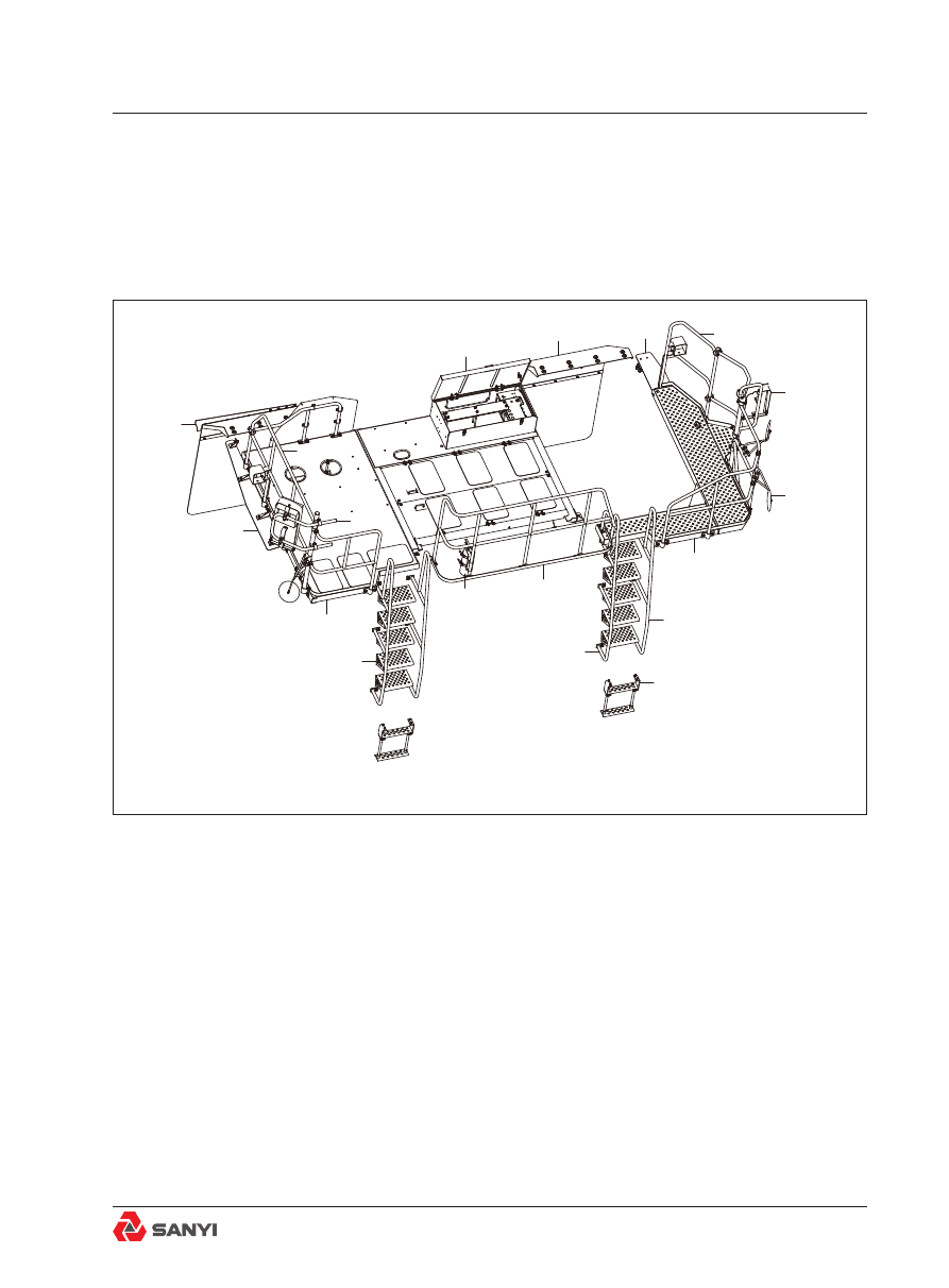
Fig.1 Fender and platform mounting

Fender And Platform Mounting

7 FENDER AND PLATFORM 

MOUNTING

7.1  Installation  of  Fender And 

Platform

18

17

16

15

14

13

12

10

9

8

7

11

6

5

4

3

2

1

1.Right-hand mudguard assembly

7.Fire extinguisher and bracket 13.Down tail mirror and bracket

2.Rubber plate

8.Front handrail assembly

14.Rear view mirror and bracket

3.Right-hand handrail assembly

9.Armrest assembly

15.Left-hand guardrail assembly

4.Rear view mirror and bracket

10.Step assembly

16.Rubber plate

5.Platform assembly

11.Armrest assembly

17.Left-hand mudguard assembly

6.Ladder assembly

12.Walkway assembly

18.Battery box assembly

Overview

The covering parts are installed on the left and 
right front support, bumper, ring beam and 
extension beam of frame. The cab is above 
them. Wherein, the platform is regarded as 
a component. It is the protective fence for 
individual components of hydraulic system and 
electrical system and protects the components 
from being contaminated and damaged during 
transportation. The platform and guardrails 
provide the passage and safety protection for 
the persons.

Removal

To remove any of the components shown in 
Fig.1&Fig.2 the following procedures should 
be carried out.
1. Position the vehicle in a level work area, 
apply the parking brake and switch off the 
engine.
2. Turn  steering  wheel  in  both  directions 
several  times  to  relieve  pressure  in  the 
steering circuit. 
3. Remove the body or lift up the body to the 

highest position and correctly fix it.

4. Attach  a  suitable  lifting  device  to  the 
component and remove mounting hardware.
Remove the component from the vehicle.

warning

To prevent personal injury and property 

damage, be sure wheel chocks, blocking 

materials  and  lifting  equipment  are 

properly secured and of adequate capacity 

to do the job safely.

Fender And Platform Mounting

Installation 

Using  a  suitable  lifting  device,  align  the 
component to be installed in position on the 
frame. Secure the component securely to the 
frame with mounting hardware removed during 
removal.

warning

To prevent personal injury and property 

damage, be sure wheel chocks, blocking 

materials  and  lifting  equipment  are 

properly secured and of adequate capacity 

to do the job safely.

Inspection and maintenance

1.  The  vibration  of  mudguard  support  is 
relatively high. It requires frequent inspection. 
Observe the position of mounting hole for the 
cracks. 
2. When the rear mirror and down  view mirror 
are installed, the operator should sit inside the 
cab and command the installation persons to 
operate so that the correct mounting angle can 
be ensured. The components should be gently 
handled and placed to prevent the collision 
and breakage. 
3. As the truck body has the relativy high width 
and height, the operator should observe the 
situations of rear mirror and down view mirror 
at first before driving the truck every time in 
order to prevent accidents. 
4. The mounting bolts of handrail should be 
frequently  inspected  for  their  tightening  to 
ensure personal safety.
5.  Check  all  components  for  abrasion.  If 
necessary, repair or replace them in time.

Installation instructions and notices for the 

gas spring in the platform assembly

1.  The  piston  rod  of  gas  spring  must  be 
installed  in  the  downward  position  and  no 
reverse installation is allowed, so that it can 

Fender And Platform Mounting

reduce the friction and ensure the optimal 
damping quality and buffering performance. 
2. The gas spring should not be subject to the 
force in the lateral direction or be used as the 
armrest.
3.  To  ensure  the  reliability  of  seal,  don’t 
damage  the  surface  of  piston  rod.  It  is 
prohibited  to  apply  the  paint,  chemical 
substance and etc. onto the piston rod. It is 
prohibited to spray and apply the paint after 
the  gas  spring  is  installed  in  the  desired 
position in advance. 
4. The gas spring is a high-pressure product. 
It is prohibited to dissect, bake and knock it at 
random.
5. It is prohibited to turn the piston rod of gas 
spring to the left. If it is required to adjust the 
orientation of joint, it can be turned to the right 
only.

6. The junction point should allow the flexible 

rotation and have no seizure phenomenon.
7.  The  selected  dimension  should  be 
reasonable. The  value  of  force  should  be 
proper. The stroke dimension of piston rod 
should have the margin of 10mm.

Fender And Platform Mounting

Cab Accessories

Fig.1 Cab accessories

1. Fixing of cab accessories

6.  Bolt

11. Handle gear shifter

2. Bolt

7. Cushion

12. Nut 

3.Cushion

8. Washer

13. Washer

4.Absorber

9. Washer

14. Washer

5. Washer

10. Bolt

15.  Bolt

8. CAB ACCESSORIES

1

11

12 13 14 15

9

7

8

10

4
5

6

3

2

3

4

4

4

Overview

Number in parentheses refer to Fig.1.
Install  the  damper  on  the  fixed  seat  of 
driver’s cab symmetrically from top to bottom; 
then fasten the absorber (4), fixing of cab 
accessories (1) and the fixed seat of driver’s 
cab with high-strength bolts(6) into a whole.

Disassembly

See Fig1 for the numbers in brackets.

Note:

 Mark and identify all removed cables, 

wire  harnesses,  pipelines  and  tubes  to 
facilitate  the  installation,  adopt  dustproof 
measure to protect tie-in.
1. Park the truck in a flat work area, lift up 
the body and install the body safety pin. See 
chapter ‘Body and Installation’.
2. Apply  parking  braking  and  shut  down 
engine.
3. Rotate steering wheel to the two directions 
for several turns and release steering system 
pressure.  Press  foot  valve  continuously 
to  release  pressure  of  brake  accumulator. 
Continuously operate the lift control handle to 
release pressure of accumulator and chock 
wheels properly.
4. Disconnect electric cables in the following 
order so as to prevent electric components 
from being damaged.
a. Disconnect the grounding cable of battery 
compensator.
b.  Disconnect  battery  cable  from  terminal 

posts (grounding cable firstly).

c .   D i s c o n n e c t   a n o d e   b a t t e r y   c a b l e 
compensator.
d. Disconnect electric contacts of ECU.
5. Disconnect the remaining electric contacts 
connected to driver’s cab assembly.
6. Carefully loosen brake pipelines on two 
brake accumulator seats to check whether the 
brake pressure is released; re-tighten brake 
pipelines.
7. Make sure to mark all steering and brake 
pipelines connected to the driver’s cab so as 

Cab Accessories

to facilitate installation; collect leaking oil with 
proper vessels, disconnect all pipelines and 
plug all opened pipelines and connectors.
8. If an air conditioner is equipped, evacuate 
the  system  before  disconnecting  air 
conditioning pipelines, and plug all opened 
pipelines and connectors. See Chapter ‘AIR 
CONDITIONING PIPELINE INSTALLATION’.
9. Make sure to mark heater pipelines; collect 
leakage  with  proper  vessels,  disconnect 
heater pipelines and plug all opened pipelines 
and connectors.
10. Make sure to mark body lifting control 
handle so as to facilitate installation; collect 
leakage with proper vessels, disconnect hoses 
on the multi-way board of driver’s cab bottom 
board  and  plug  all  opened  pipelines  and 
connectors.
11.  Make  sure  that  all  the  connectors 
connected  to  driver’s  cab  assembly  are 
removed before disassembly.
12.  Suspend  driver’s  cab  assembly  with 
proper lifting device and straighten loosened 
parts;  remove  absorber  (4),  cushion  (3)  
washer (5) and bolt (2

6) of supporting beam 

of driver

s cab assembly. 

Note:  For  disassembly  of  driver

s  cab 

assembly,  special  lifting  device  and  lever 
with  pad  should  be  used  to  prevent  over-
concentrated stress of hook, chain and wire 
rope at hook-on points of driver

s cab.

13. Carefully lift driver

s cab assembly to a 

proper working platform.
14. Loosen the bolt (10), washer (8

9), take 

off the cushion (7).
15. Loosen the bolt (15), washer (13

14) and 

nut (12), take off the handle gear shifter (11).

Installation 

Note

:  Tighten  all  fasteners  according  to 

Section  ‘

TECHNICAL  CONDITIONS  FOR 

TIGHTENING  TORQUES  OF  STANDARD 

BOLTS AND NUTS

’ in the manual.

Note

: According  to  the  descriptions  of 

Cab Accessories

‘Schematic diagram of brake’ in the manual, 
tighten all of the hydraulic pipelines equipped 
with the O-ring end face seal port and replace 
the O-rings.
1. Install the handle gear shifter (11), tighten 
the bolt (15), washer (13

14) and nut (12).

2. Install the cushion (7), tighten the bolt (10), 
washer (8

9).

3. Check whether the rubber pad is damaged. 
If it is damaged, replace it. To install the new 
rubber pad, use the water or proper lubricant 
to  lubricate  it  and  then  install  it  onto  the 
driver's cab assembly. Use the screwdriver to 
get the rubber pad completely in position.
4. Use a proper hoisting device to place the 
driver's cab assembly onto the driver’s cab 
supporting  beam.  Care  must  be  taken  to 
prevent the pipelines and components from 
interfering with the lower side of driver's cab 
assembly. 
5.  Use  absorber  (4),  cushion  (3)    washer 
(5) and bolt (2

6) to fix parts assembly of 

Cab(1) on the supporting beam of driver’s cab 
assembly.
6. Remove plug from lifting control handle 
pipeline; connect pipeline according to signs 
made  upon  removal  and  fix  all  pipelines 
properly.
7.  Remove  the  plug  from  brake  steering 
pipeline; connect pipeline according to signs 
made  upon  removal  and  fix  all  pipelines 
properly.
8 .   E x c e p t   f o r   b a t t e r y   c a b l e ,   b a t t e r y 
compensator  cable  and  EUC  connector, 
connect all electric connectors according to 
signs made upon removal.
9. Remove plug from heating pipeline and 
connector;  connect  pipeline  according  to 
signs made upon removal and tighten heating 
pipelines properly.
10. If an air conditioner is equipped on the 

truck, connect pipeline to evaporator and refill 

system.
11.  Connect  electric  connectors  in  the 

Cab Accessories

following order:
a. Connect electric connectors removed from 
ECU.
b. Connect anode battery cable compensator.
c. Connect battery cable to the terminal posts 
(priority is given to anode cable).
d.  Connect  the  grounding  cable  of  battery 
compensator.
12. Check driver’s cab assembly to ensure 
that all pipelines and cable harnesses have 
been reconnected after being removed.
13.  Refill  the  two  hydraulic  oil  tanks  with 
oil  according  to  stipulations  in  section 
‘LUBRICATION AND MAINTENANCE’. Check 
the coolant level in the overhead water tank of 
radiator. If it is low, then add the coolant. See 
section ‘LUBRICATION AND MAINTENANCE’.
14.  Start  engine,  check  for  leakage, 
tighten  pipeline  and  joints  according  to 
the  requirements,  heat  truck  up  to  normal 
operation  temperature  and  check  all 
connections for leakage.
15. Check whether all instruments and control 
elements operate normally. Remove the body 
safety pin and lower down the body.

Cab Accessories

Fig.2 Cab assembly

1. Steering column mounting

6. Washer

2. Throttle controller assembly

7. Bolt

3. Cab harness

8. Seat mounting assembly

4. 

Evaporator assembly

9. Switch and meter

5. Washer 

10. Control panel of air conditioning

8.1 Parts Assembly of Cab 

10

6
5

7

4

1

8

9

3

P

2

Cab Accessories

Overview

Numbers in parentheses refer to Fig.2.
Parts assembly of cab complies with safety 
rules as stipulated in ISO/SAE FOPS (falling 
object protective structure) and ROPS (rollover 
protective structures). Parts assembly of cab 
is accessible from two sides of the truck, with 
light-colored glass and a good view. The air 
conditioner is installed as standard on the 
driver's  cab  assembly.  See  Chapter  ‘AIR 
CONDITIONING PIPELINE INSTALLATION’.

Disassembly

Note

: Mark and identify all removed cables, 

wire  harnesses,  pipelines  and  tubes  to 
facilitate the installation.
1. Ensure parts assembly of cab is placed on 
a proper working platform which is stable and 
free of vibration.
2. Use a proper tool to dismantle the driver's 
seat and co-driver's seat as well as the base. 
See the installation of seat base.
3. Use the wrench to remove the flat washer 
(5),  washer  (6)  and  bolt  (7)  fixing  the 
evaporator. Disconnect the cables and wire 
harnesses connected to the evaporator, and 
classify and place them into the storage box.
4.  Disconnect  the  pipelines  and  pipes 
connected to the evaporator, 
and synchronously make the marks properly. 
Plug all open pipelines and joints.
5. Place all removed objects in a visible place 
to facilitate the succeeding installation.

Installation 

Note

:Tighten  all  fasteners  to  standard 

torques listed in Section 36.2, TECHNICAL 
CONDITIONS FOR BOLTS AND NUTS.
1. Use a proper tool to install the driver's seat 
and co-driver's seat as well as the base. See 
the installation of seat base.
2. Use the wrench to tighten the flat washer 
(5), spring washer (6) and bolt (7) fixing the 
evaporator.  Connect  the  cables  and  wire 

Cab Accessories

harnesses correctly according to the marks.
3.  Connect  all  pipelines  and  tubes  to 
evaporator in the order as marked.

Cab Accessories

Fig.3 Body of cab

1. Body of cab welding

3. Door assembly

2. Rear window glass

4. Front windshield glass

8.1.1 Body of cab

1

4

2

3

Cab Accessories

Door assembly

Descriptions

See Fig.3 for the numbers in the brackets.

The door assembly has the welded steel plate 
structure and the hinge connection in its rear 
part. The  window  glass  is  divided  into  the 
front and rear parts. Door limiter can prevent 
excessive swing of door. The door assembly 
can be removed as an assembly from inside 
the driver’s cab. But the lock, handle, glass 
and etc. can be separately removed when the 
door is connected onto the cab.

Disassembly and installation

1. Open the door assembly and use a proper 
hoisting device to hoist it. Remove the cover 
and splint pin from the hinge. Use a proper 
screw driver to remove the pin from the hinge. 
Remove the door assembly from the driver's 
cab assembly.
2. Install the new plug-pin onto the hinge.
3. Use the proper hoisting device to hoist the 
door assembly. Align the door assembly with 
the hinge of driver’s cab.  To install the pin, 
perform the alignment with the hole and use 

the splint pin for the fixation.

4.  Check  whether  the  door  assembly  (3) 
is  installed  correctly  and  whether  the  lock 
function is normal.

Replace front windshield glass

See Fig.3 for the numbers in the brackets.

Attention

Before replacing the broken glass, 

must be sure the glass accord with rule of low, 
replace front windshield glass as following 
method.
Attention

Before eliminate glass glue, front 

windshield glass must be fixed.

1. Fixed front windshield glass with magnet, 
eliminate glass glue by cutter, disassemble 
front windshield glass.
2. Lay on the special glue on the edge of glass 
and window frame.

Cab Accessories

3. Defend the edge of window frame by paper 
tape.
4. Lay on the glass glue on the window frame.
5. Adjust the clearance of glass and double 
side of window frame

fix up the glass.

6. Scrape glass glue between glass and frame 
averagely.
7. Fill in the clearance between glass and the 
double side of window frame with glass glue.
8. Eliminate the dirty glass glue.
Attention

The thickness of glass glue should 

exceed 8~10mm. In winter

the glass glue 

must be roasted to 35~40

℃,

which the time 

of calefaction is 6~8 hours, when replaced the 
glass, the car must be stayed over 24 hours.

Replace rear window glass

See Fig.3 for the numbers in the brackets.

Attention

Before replacing the broken glass, 

must be sure the glass accord with rule of 
low, replace rear window glass as following 
method.
Attention

Before eliminate glass glue, rear 

window glass must be fixed.

Attention

Before replacing the broken glass, 

must be sure the glass accord with rule of 
low, replace rear window glass as following 
method.
Attention

Before eliminate glass glue, rear 

window glass must be fixed.
1.  Fixed  rear  window  glass  with  magnet, 
eliminate glass glue by cutter, disassemble 
front windshield glass.
2. Lay on the special glue on the edge of glass 
and window frame.
3. Defend the edge of window frame by paper 
tape.
4. Lay on the glass glue on the window frame.
5. Adjust the clearance of glass and double 
side of window frame

fix up the glass.

6. Scrape glass glue between glass and frame 
averagely.
7. Fill in the clearance between glass and the 
double side of window frame with glass glue.

Cab Accessories

8. Eliminate the dirty glass glue.

Detection of water leakage

It  is  required  make  detection  over  water 
leakage after glass is mounted. Spray water 
onto the sealing position from outside driver’s 
cab. An assistant should mark where leakage 
occurs inside driver’s cab. Apply sealant from 
outside and start from the leakage outwards. 
Spread sealant on the surrounding area of 
leakage.

Cab Accessories


Content      ..     15      16      17      18     ..