SANY SRT95C Off-Highway Truck. Service Manual - page 15
 

  Index      Manuals     SANY SRT95C Off-Highway Truck. Service Manual


Search            copyright infringement  


Content      ..     13      14      15      16     ..


SANY SRT95C Off-Highway Truck. Service Manual - page 15


5.1.1 Engine - power takeoff 

(Oil feeding screw plug)

45

45

45

 (Oil level plug

(Drain plug)

12

11

10

9

8

31

26

27

19

20

28

18

26

22

24

23

25

21

44

43

42

41

40

39

37

38

35

36

34 33

32 30

29

17

16

15

14

13

5 6

7

4

3

2

1

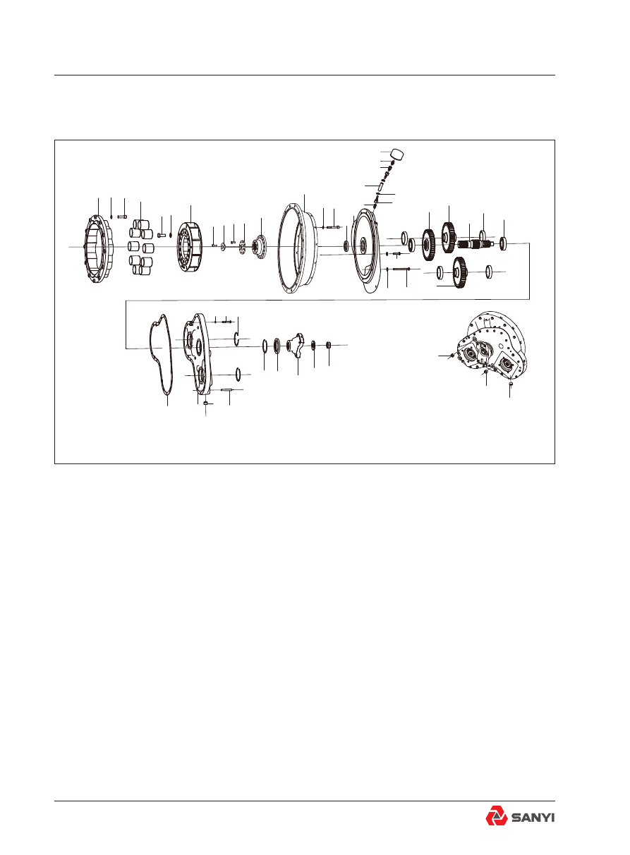
Fig.2 - Exploded View of Engine - Power Takeoff

1. Outer ring, aluminum

13. Transitional disc

25. Drive gear

37. Shell cover

2. Washer

14. Washer

26. Driven gear

38. Plug

3. Screw

15. Bolt

27. Drive shaft

39. Pin

4. Elastic body

16. Oil Seal

28. Bearing

40. Ring, retainer

5. Bolt

17. Shell seat

29. Bearing

41. Oil Seal

6. Washer

18. Rubber adaptor

30. Bolt

42. Yoke

7. Inner ring, aluminum

19. Breathing tube

31. Bolt

43. Washer

8. Screw

20. Pipe connector

32. Washer

44. Nut

9. Pressure cover

21. Pipe connector

33. Ring, retainer

45. Plug

10. Bolt

22. Breather

34. Bolt

11. Pressure cover

23. Throat collar

35. Washer

12. Sleeve, shaft

24. Pipe connector

36. Gasket

Installation of Engine

Description operation

Numbers in parentheses refer to Fig.2.
The function of the power takeoff (PTO), as 
the name implies, is to provide the means of 
mounting and driving auxiliary components.
The hydraulic pump on the shell cover (37) 
and its input shaft is meshed with the internal 
spline in the hub of driven gear (26).
The major components of the PTO assembly 
are: Shell seat (17), shell cover (37), drive 
shaft (27), drive gear (24) and driven gear (26).
As drive shaft (27) is driven by the engine 
crankcase, drive gear (25) turns to drive driven 
gears (26). The hydraulic pump drive shafts, 
meshed in the hub of driven gears (26), turn 
with driven gears (26) to operate the hydraulic 
pump which, in turn, supplies hydraulic oil to 
the body hoist system and steering system 
and disc brake assemblies.

Removal

Numbers in parentheses refer to Fig.2, unless 

otherwise specified.

warning

To prevent personal injury and property 

damage, be sure wheel blocks, blocking 

materials  and  lifting  equipment  are 

properly secured and of adequate capacity 

to do the job safely.

1. Position the vehicle in a level work area, 
apply the parking brake and switch off the 
engine.
2. Turn  steering  wheel  in  both  directions 
s e v e r a l   t i m e s   t o   r e l i e v e   p r e s s u r e   i n 
accumulator and steering system. Block all 
road wheels.
3. Disconnect driveline from yoke (42) at PTO 
assembly.
4. Drain oil from power takeoff housing by 
removing drain plug (45) from shell seat (17). 

Installation of Engine

Reinstall drain plug (45) securely.
5.  Match  mark  main  hydraulic  pump  and 
combination  gear  pump  mounting  flange 
and shell cover (37) so that the pump can be 
installed in the same position at installation.
6. With suitable blocking or lifting equipment, 
support the hydraulic pump and combination 
gear pump before loosening attaching bolts. 
Remove Bolts and lock washers from main 
hydraulic pump and combination gear pump 
clear of PTO assembly.
7. Match mark engine flywheel housing and 
shell seat (17) so that PTO assembly can be 
installed in the same position at installation.
8. Attach  a  suitable  lifting  device  to  PTO 
assembly and remove bolts (30 & 31) and lock 
washers (32) securing PTO assembly to the 
engine flywheel housing. Remove the rubber 
adaptor (18). Carefully lower PTO assembly 

from the flywheel housing and move to a clean 

work area for disassembly.
9. Remove the bolt (15) and washer (14) from 
the  engine  flywheel.  Carefully  remove  the 
transitional disc (13).
10. Remove the bolt (3) and washer (2) from 

the aluminum outer ring (1) of engine flywheel. 

Carefully remove the aluminum outer ring (1).

Disassembly

Numbers in parentheses refer to Fig.2, unless 

otherwise specified.

1. Remove the locknut (44) and washer (43) 
from drive shaft (27). Pull yoke (42) from drive 
shaft (27).
2. Remove the pins (39) from the shell cover 
(37). 
3. Place shell cover (37) yoke side up on a 
work bench. Pry oil seal (41) from shell cover 
(37) and discard.
4. Turn over PTO assembly. Remove the bolts 
(5) and washers (6) from the aluminum Inner 
ring (7). Pull aluminum Inner ring (7) from 
shaft sleeve (12).
5. Remove the screw (8) from the drive shaft 

Installation of Engine

(27). Pull pressure cover (9) from drive shaft 
(27).  Remove  the  bolt  (10)  from  the  shaft 
sleeve (12). Pull pressure cover (11) and shaft 
Sleeve (12) from drive shaft (27).
6. Remove the bolts (34) and washers (35) 
from  the  shell  cover  (37).  Pull  shell  cover 
(37) and gasket (36) from the shell seat (17). 
Discard gasket (36).
7. Remove snap rings (33 & 40) from pump 
and drive shaft bores. Drive bearings (28 & 29) 
from shell cover (37) with a sleeve or soft steel 
drift. Drive on the outer race of bearings (28 
&29) taking care not to damage the bearings.
8. Slide drive gear (25) from drive shaft (27), 
and pull driven gears (26) from shell seat (17).
9. Pull drive shaft (27) from shell seat (17). Pry 
oil seal (16) from shell seat (17) and discard.
10. Pull bearings (28 & 29) from shell seat (17) 
with a suitable bearing puller.

Inspection

Numbers in parentheses refer to Fig.2, unless 

otherwise specified.

1.  Wash  all  parts  thoroughly  in  a  suitable 
solvent and dry all but bearings (28 & 29) with 
compressed air. Dry bearings (28 & 29) with a 
clean lint free cloth.
2. Check the condition of splines and teeth on 
gears (25 & 26), drive shaft (27) and yoke (42) 
for burrs or signs of wear.
3. Lubricate bearings (28 & 29) with oil and 
check operation by spinning bearings by hand. 
Do not spin bearings with compressed air. 
Inspect bearing bores for out of roundness. 
Replace bearings, if required.
4. Inspect shell seat (17) and shell cover (37) 
for cracks. If either shell seat (17) or shell 
cover (37) are damaged, both parts must be 
replaced as an assembly.
5. Visually check oil seal lip contact surfaces 
on drive shaft (27) and yoke (42) for nicks, 
dents, scratches, wear, or corrosion. Replace 
as necessary.
6.  Inspect  aluminum  outer  ring  (1)  and 

Installation of Engine

aluminum inner ring (7) and shaft sleeve (12) 
of shaft coupling for cracks. If either aluminum 
outer ring (1) or aluminum inner ring (7) or 
shaft sleeve (12) are damaged, the parts must 
be  replaced  as  an  assembly. At  the  same 
time, check the elastic body (4) and bolt (5 & 
10) and screw (3 & 8) and pressure cover (9 & 
11).

Assembly

Numbers in parentheses refer to Fig.2, unless 

otherwise specified.

Note

: Prior to assembly, lubricate all seal lips 

and surfaces with lubricant specified in Section 

36.1, LUBRICATION SYSTEM.

Note

: Tighten all fasteners without special 

torques specified to standard torques listed, 
STANDARD  BOLT  AND  NUT  TORQUE 
SPECIFICATIONS.

warning

To prevent personal injury and property 

damage, be sure lifting device is properly 

secured and of adequate capacity to do the 

job safely.

1. Press bearings (28 & 29) into their bores in 
shell seat (17).
2. Install driven gears (26) and drive shaft (27) 
into shell seat (17). Slide drive gear (25) over 
drive shaft (27) to its proper location.
3. Install the new gasket (36) on the shell seat 
(17). Install the shell cover (37) onto the shell 
seat (17). Install the pins (39) into the shell 
cover (37) and the shell seat (17).
4. Press bearings (28 & 29) into their respective 
bores in shell cover (37). Install rings (33 & 40) 
into the shell cover (37). 

5. Use the bolt (34) and washer (35) to fix the 

shell cover (37) onto the shell seat (17).
6. Install new oil seal (41) into centre bore in 

the shell cover (37) so that it is flush with shell 

Installation of Engine

cover (37) face. 
7. Turn over PTO assembly. Install new oil 

seal (16) in the shell seat (17) so that it is flush 

with shell seat (17) face. 
Note: When installing new oil seals, install them 
with the oil lip (larger of the two lips with the 
spring behind it) facing inward. Care should 
be taken to prevent damage to seal lips during 
assembly.
8. Install yoke (42) on drive shaft (27) end and 
secure with hardened washer (43) and locknut 
(44). Tighten locknut (44) to fasten it after the 
paste is applied to it. The torque is 850 - 1050 
Nm.
9.  Install  the  pressure  cover  (11)  of  shaft 
coupling onto the shaft sleeve (12). Use the 
bolt (10) to fasten it after the paste is applied 
to it. The torque of bolt (10) is 104Nm.Install 
the shaft sleeve (12) of shaft coupling onto 
the input end of drive shaft (27). Then install 
the pressure cover (9) onto the drive shaft 
(27). Use the set screw (8 to fasten it after the 
paste is applied to it. The torque of set screw 
(8) is 60Nm. Then install the aluminum inner 
ring (7) of shaft coupling onto the shaft sleeve 
(12). Use the bolt (5) and washer (6) to fasten 
it after the paste is applied to it. The torque of 
connecting bolt (5) is 350Nm. 
10.  Install  the  aluminum  outer  ring  (1)  of 

shaft coupling onto the flywheel disc and use 

the shaft coupling fastening screw (3) and 
washer (2) to fix it. The torque of connecting 
screw (3) for the aluminum outer ring (1) and 

flywheel disc of shaft coupling is 170Nm. The 

thread anti-loosing paste should be applied for 
tightening.
11. Install the elastic body (4) in aluminum 

inner ring (7). Attach a suitable rope to fix the 

elastic body (4).

Installation

Numbers in parentheses refer to Fig.2, unless 

otherwise specified. 

Note

:When  reassembling  PTO  assembly. 

Installation of Engine

to  the  engine  flywheel  housing,  and  main 
hydraulic  and  tandem  pumps  to  PTO 
assembly.  be  sure  to  align  match  marks 
inscribed during disassembly.

Note

: Tighten all fasteners to standard torques 

listed, STANDARD BOLT AND NUT TORQUE 
SPECIFICATIONS.
1. Install the transitional disc (13) onto the 
flywheel housing and use the Bolt (15) and 
washer  (14)  to  fix  it.  Use  suitable  lifting 
equipment, position Power take-off assembly 
into  the  aluminum  outer  ring  (1)  of  shaft 
coupling. Remove the rope of elastic body (4). 
Secure PTO assembly to the transitional disc 
(13) with bolts (30 & 31) and washers (32).
2. Using suitable lifting equipment, position 
hydraulic pump over its mounting studs and 
secure with bolts removed during removal. 
3. Reconnect driveline to yoke (42). Install 
rubber adaptor (18) into shell seat (17).
4. Remove oil level plug and drain plug (45) 
from the front shell cover (37) and the shell 
seat (17) respectively. Add the lubricating oil 
into the PTO assembly from the drain plug (45), 
until the oil reliefs from the opening of oil level 
plug (45). Then install and fasten the oil level 
plug and drain plug (45) respectively.
5. Start the engine and bring oil to correct 
operating temperature. Check for leaks and 
correct as necessary.
6. Remove wheel blocks from all road wheels.

Maintenance

Numbers in parentheses refer to Fig.2, unless 

otherwise specified.

Note: Refer to Section 36.1, LUBRICATION 
SYSTEM for recommended check and drain 

intervals and lubricant specifications.

Oil level check
Remove oil level plug (45) from front part of 
shell cover (37), if oil is not showing in oil level 
plug (45), add lubricant until oil is to oil level 
plug  (45).  Reinstall  oil  level  plug  (45)  and 
tighten securely.

Installation of Engine

Draining and refilling

To  drain

:  Remove  drain  plug  (45)  from 

shell seat (17) and drain oil into a suitable 
container. Reinstall drain plug (45) securely 
when draining is complete.

To refil

l: Remove oil level plug (45) from the 

front of shell cover (37) and fill PTO assembly. 
until oil flows from the oil level port. Install oil 

level plug (44) in shell cover (36) and tighten 
securely.

Installation of Engine

5.2 Installation of Compressor

Disassembly of compressor

1. Disconnect the electrical connection from 
the clutch of compressor (5). 
2. Loosen the nut and washer on the adjusting 
screw rod (9) and release the tension of V-belt 
(7).
3. Loosen the nut (1), bolt (6) and washers (2

3). Regulate the adjusting screw rod (9). The 
V-belt (7) should be able to freely slip from the 
groove of compressor (5).
4. Remove the nut (1), screw (4) and washers 
(2

3) from the compressor (5). Detach the 

adjusting screw rod (9) from the compressor.
5.  Support  the  compressor  (5).  Remove 
the  adjusting  gasket  (10),  washers  (2

3) 

and nut (1) fixing the compressor (5) onto 

Fig.1 Assembly drawing of compressor

11

1 2 3

4

5

6

7

8

9

10

1. Nut

7. V-belt

2. Washer

8. Nut

3. Washer

9. Adjusting screw rod

4. Screw

10. Adjusting gasket

5. Compressor

11. Compressor support

6.Bolt

Installation of Engine

the  compressor  support  (11).  Remove  the 
compressor (5) from the compressor support 
(11). 
6. Remove the compressor support (11) from 
the engine.
Note: If it isn’t required to replace the V-belt (7), 
then it will be unnecessary to remove it from 
the engine.

Installation of compressor

1. Install the compressor support (11) onto the 

engine and use the removed fasteners to fix it 

properly.
2.  Install  the  compressor  (5)  onto  the 
compressor support (11) and use the removed 
fasteners to fasten it. They can’t be completely 
tightened in this step.
3. Install the V-belt (7) onto the rear groove of 
engine fan pulley and then install it onto the 
rear groove of compressor (5).
4. Insert the upper part of adjusting screw rod 
(9) through the mounting hole of compressor 
(5). Insert the screw (4) through the mounting 
hole of compressor. Use the washers (2

3) 

and nut (1) to fasten the adjusting screw rod (9) 
and compressor (5). They can’t be completely 
fastened in this step.
5. Insert the lower part of adjusting screw rod 
(9) through the mounting hole of base seat. 
Insert the 

Screw

(4) through the mounting hole 

of compressor support (11). Use the washers 
(2

3)  and  nut  (1)  to  fasten  the  adjusting 

screw rod (9) and compressor support (11). 
They can’t be completely fastened in this step.
6. Fix the compressor (5). Fasten the washers 
(2

3) and nuts (1) in Step 4 and 5.

7. Adjust the V-belt (7) of compressor with the 
adjusting screw rod (9), until a deflection of 
about 10mm appears when the center part 
of V-belt (7) is pressed by thumb. Tighten all 
fasteners.
8. Connect the electric circuit of the clutch of 
compressor (5).

Installation of Engine

6   T R A N S M I S S I O N   A N D 

MOUNTING

6.1 Transmission  Mounting

Fig.1 Transmission and Mounting

Transmission And Mounting

25 24

23

26

1

2

3

4

5

6

7

8

9

2

10

11

12

13

14

11

15

16

17

18

19

20

20
21

18

22

1. Filler hose

10. Bolt

19. Plate

2. Flange nut

11. Washer

20. Shock mount

3. Retainer plate

12. Plate

21. Ringer

4. Output flange

13. Shock mount

22. Nut

5. Transmission

14. Ringer

23. Bolt

6. Ring

15. Nut

24. Washer

7. Trunnion

16. Power take-off assembly

25. Bracket

8. Input flange

17. Bolt

26.Transmission 
retarder control

9. Retainer plate

18. Washer

Description

Numbers in parentheses refer to Fig.1.
F o r   t r a n s m i s s i o n   m a k e ,   m o d e l   a n d 
specification, refer to  ‘GeneralL information’. 
For  transmission  switches,  sensors  and 
instruments, refer to Section 8.1.7, 'Switches 
and sensors'.
For transmission servicing and repair data, 
refer  to  the  transmission  manufacturers 
service manual.
The  transmission  is  remote  mounted  in 
the frame and is supported by trunnion (7) 
assembly  at  the  front  and  two  mounting 
brackets  (25)  at  the  rear.Integral  with 
transmission (5) assembly are torque converter 
and planetary gearing. There are six forward 
gears and one reverse gear with automatic 
lockup in all speed ranges. Operation of the 
transmission is by the Commercial Electronic 
Control (CEC) Shift System. A brief description 
and  operation  of  the  main  transmission 
components are as follows:

Torque converter

The  torque  converter  consists  of  three 
elements -pump, turbine, and stator. The pump 
is the input element and is driven directly by 
the engine. The turbine is the output element 
and is hydraulically driven by the pump. The 
stator  is  the  reaction  (torque  multiplying) 
element. When the pump turns faster than 
the turbine, the torque converter is multiplying 
torque.  When  the  turbine  approaches  the 
speed of the pump the stator starts to rotate 
with the pump and turbine. When this occurs, 
torque  multiplication  stops  and  the  torque 

converter functions as a fluid coupling.

Lockup clutch

The lockup clutch is located inside the torque 
converter and consists of three elements - 
piston, clutch plate, and backplate. The piston 
and backplate are driven by the engine and 
the clutch plate, located between the piston 

Transmission And Mounting

and  backplate,  is  splined  to  the  converter 
turbine. The  lockup  clutch  is  hydraulically 
engaged and released in response to electrical 
signals from the ECU. It engages when the 
vehicle  reaches  a  predetermined  speed. 
Engagement of the lockup clutch provides a 
direct drive from the engine to the transmission 
gearing. This eliminates converter slippage 
to  provide  maximum  fuel  economy.  The 
lockup clutch releases at lower speeds (and 
momentarily during shifts). When the lockup 
clutch is released, drive from the engine is 
transmitted hydraulically through the converter 
to the transmission gearing. The lockup clutch 
also releases when the ECU detects certain 
undesirable conditions.

Planetary gears and clutches

A series of planetary gears and shafts provide 
the gear ratios and directions of travel for the 
vehicle. Power flow through the planetaries 
is controlled by multiple clutch packs. The 
clutches are applied and released hydraulically 
in response to electrical signals from the ECU.

Hydraulic retarder

A vaned rotor and two vaned stators are the 
basic components of the retarder. Application 
of the retarder control valve fills the cavity 
around  the  rotor  with  oil  when  the  vehicle 
must be slowed on steep downgrades. When 
the cavity is emptied, the rotor is free of drag. 
Maximum retarder effect occurs in the lowest 
gear range with foot off of the accelerator 
pedal. Long continuous use of the retarder 
will raise transmission oil temperature. Short 
periods of full release, to interrupt continuous 
application,  will  help  prevent  overheating. 
During normal operation the dash mounted 
transmission oil temperature gauge should 
read  in  the  green  zone.  However,  during 
transmission retarder operation oil temperature 
can enter the yellow 'Retarder On' zone but 
should not enter the red zone.

Transmission And Mounting

Transmission oil cooler

The transmission oil is cooled by a separate 
oil cooler mounted between the radiator and 
transmission to maintain transmission oil within 
its  required  operating  temperature  range. 
Refer to Section 33,'oil cooler assembly'.

Transmission oil filter

The transmission oil filter is mounted at the left 

hand side of the transmission. It is installed in 
the transmission oil lines to remove dirt and 
other contaminants from the transmission oil to 
minimise wear and provide maximum service 
life for the transmission. Refer to Section 30, 

'transmission oil filter'.

Removal

Numbers in parentheses refer to Fig.1.

warning

To prevent personal injury and property 

damage, be sure wheel blocks, blocking 

materials  and  lifting  equipment  are 

properly secured and of adequate capacity 

to do the job safely.

High electrical current can cause sparks 

and personal injury from burns. Switch 

circuit breakers to the 'Off' position before 

removing  any  electrical  components. 

Remove battery ground cable first, and 

reconnect  last,  to  prevent  damaging 

electrical components.

A n y   t i m e   t h e   b a t t e r y   e q u a l i z e r   i s 

disconnected from the batteries, remove 

ground cable first, and reconnect last, to 

prevent damaging the component.

1. Position the vehicle in a level work area, 
raise the body and secure in place with the 
body safety pins. Refer to Section 23,'Body 
and Installation'.
2. Apply  the  parking  brake  and  switch  off 

Transmission And Mounting

the  engine.  Turn  steering  wheel  in  both 
directions several times to relieve pressure 
in the steering system. Operate the treadle 
valve  continuously  to  discharge  the  brake 
accumulators.
3. Block all road wheels.

Note

:  It  is  important  that  the  electrical 

connections are removed in the order listed 
in step 4 to prevent damage to the electrical 
components.
4.  Disconnect  battery  equalizer  ground 
connection  from  the  batteries.  Disconnect 
battery cables from terminal posts (ground 
cable  first).  Disconnect  battery  equalizer 
positive  connection.  Disconnect  electrical 
connections at the ECU.
5. Using suitable lifting equipment, support 
transmission  guard  and  remove  mounting 
hardware securing the guard to the frame. 
Remove transmission guard.

6. Disconnect driveline from input flange (8) at 

the front of transmission (5). Refer to Section 
19, 'Driveline Installation'.
7.  Disconnect  driveline  from  output  flange 
(4) at the rear of transmission (1). Refer to 
Section 19, 'Driveline Installation'.
8. Drain the oil from transmission (5).
9. Disconnect the transmission retarder cables 
at transmission (5).
10. Disconnect transmission oil cooler lines 
and oil filter lines from transmission (1). Cap 
all open lines and fittings to prevent entry of 
dirt.
11. Disconnect all remaining hydraulic lines 
attached to transmission (5). Cap all open 

lines and fittings to prevent entry of dirt.

12. Disconnect all electrical connections and 
cables attached to the transmission.
13. Disconnect filler hose(1) attached to the 
transmission(5).
14. Install suitable lifting eyes into the holes 
provided at the top of transmission (5) housing 
and secure a suitable lifting device to the eyes.
15.  Remove  bolts  (10),  washers(11), 

Transmission And Mounting

Plates(12)and nuts(15) securing trunnion (7) 
to the frame.
16.  Remove  bolts  (17),  washers(18), 
Plates(19)and nuts(22) securing brackets(25) 
to the frame.
17. Check to make certain that all hydraulic 
lines  and  electrical  connections  fitted  to 
transmission  (5)  have  been  disconnected 
before moving transmission (5).
18.  Carefully  manoeuvre  transmission  (5) 
out of the frame mounting and lower onto a 
suitable dolly or pallet.
19.  Move  transmission  (5)  assembly  to  a 
suitable work area or onto a work stand for 
further disassembly, if necessary.

Disassembly

Numbers in parentheses refer to Fig.1.

Note

: Refer to the transmission manufacturers

Service  Manual  if  transmission  service  or 
repair is required.

1. Remove flange nut (2) and retainer plate (9)
securing input flange (8) on transmission (5). 
Pull input flange (8) from transmission (1).

2. Pull trunnion (7)  from transmission (5) and 
remove ring (6) and shock mounts (13) from 
trunnion (7), if required.

3. Remove flange nut (2) and retainer plate (3)
securing output flange (4) on transmission (5). 
Pull output flange (4) from transmission (5).

4.  Remove  bolts  (23)  and  washers(24) 
securing brackets (25) on transmission (5) and 
remove brackets (25).
5. If required, remove shock mounts (20) from 
mounting brackets (25).

Assembly

Numbers in parentheses refer to Fig.1.

1.If removed, fit shock mounts(13) and ring (6)

to  trunnion  (7).  Install  trunnion  (7)  to 
transmission (5).

2.If removed, fit shock mounts (20) to brackets 

(25).  Install  brackets  (25)  on  transmission 
(5) and loosely secure with bolts (23) and 

Transmission And Mounting


Content      ..     13      14      15      16     ..