SANY SRT95C Off-Highway Truck. Service Manual - page 13
 

  Index      Manuals     SANY SRT95C Off-Highway Truck. Service Manual


Search            copyright infringement  


Content      ..     11      12      13      14     ..


SANY SRT95C Off-Highway Truck. Service Manual - page 13


warning

To prevent personal injury and property 

damage, be sure wheel blocks, blocking 

materials  and  lifting  equipment  are 

properly secured and of sufficient capacity 

to do the job safely.

1. Place the truck in a flat area, apply parking 

brake and shut down the engine.
2. The steering wheel turns for several circles 
in the two directions to relieve the pressure in 
steering system. Block all wheels, except the 
one to be raised. Use wooden blocks 100 mm 
x 100 mm (4 in x 4 in) or larger.
3. Support the truck with jack for removal of 
tyre, but do not jack up the truck.
4. Completely deflate tyre by removing valve 
cap and core. Check valve stem by running a 
piece of wire through the stem to make sure it is 
not plugged. See warning under 'Preparation 
for servicing' .
5. Loosen the nut (11) on the wheel hub. But 
do not remove from the stud (9).
6. Jack the truck up only as high as necessary 
to remove wheel from truck, and place safety 
blocks under the frame.
7. Support the tyre with a chain or rope of 

sufficient strength attached to a suitable lifting 

device. Remove the nut(11) and clamp(10) 
from the wheel stud (9). Remove wedge band 
(8) and lift tyre and rim assembly clear.
8.  If  inner  tyre  and  rim  assembly  is  being 
removed, remove spacer band (7), attach a 
lifting device to tyre and rim assembly, and 
remove from truck.

Dismounting tyre from rim

Numbers in parentheses refer to Fig.2, unless 

otherwise specified.

Note

: The following instructions are applicable 

to  use  of  hand  tools.  For  procedures  and 
tooling required to dismount the tyre from the 

1

2 3

B

4

A

C

5

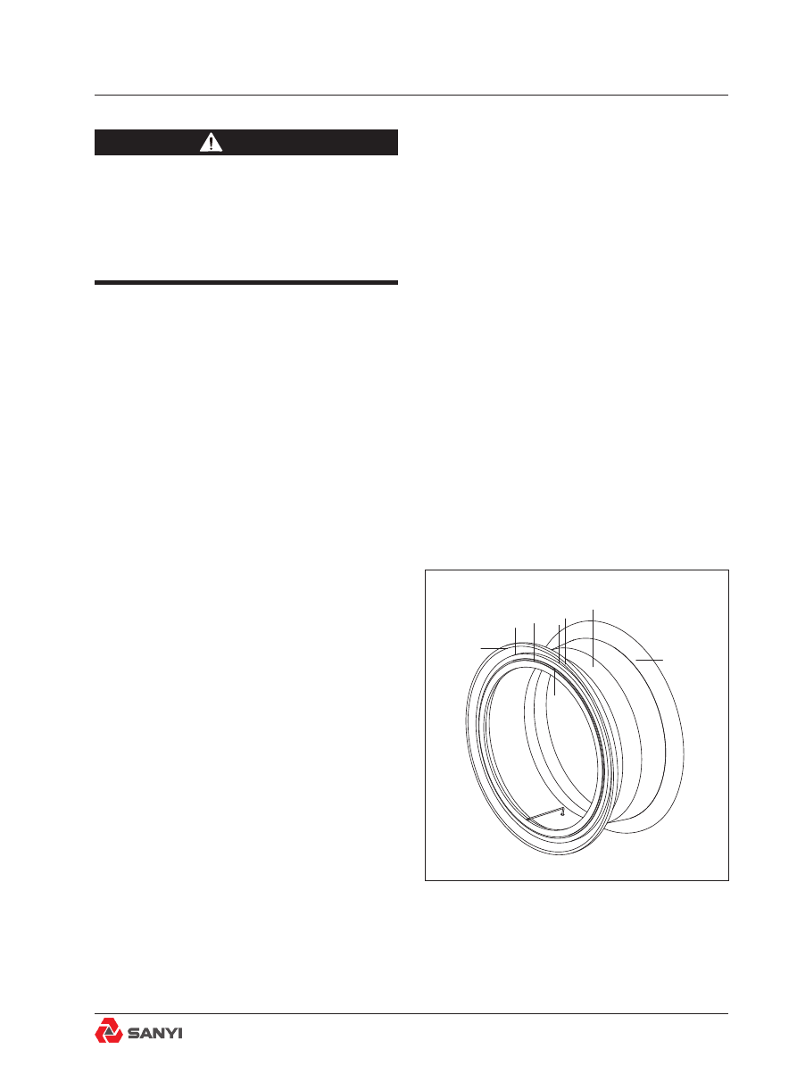
Fig.2 Rim assembly

1. Outer flange

4. Rim

2. Bead Seat Band

5. Inner flange

3. Lock ring

Rear Wheel Assembly

rim, using hydraulic tools, contact the tyre 
manufacturer.

warning

When  lifting  tyre  from  rim,  be  sure  the 

device is of sufficient capacity and properly 

secured to do the job safely.

1.  Completely  deflate  tyre  if  not  done 
previously. See warning under 'Preparation for 
servicing' . Tape valve threads to protect from 
damage, leaving valve end open to avoid any 
possibility of trapping air inside the tyre.
2. As shown in Fig.3, break outer tyre bead 

loose by placing the flat hooked end of a pry 

bar, into one of the breaking slots (C) between 

the bead seat band (2) and outer flange (1). A 

length of pipe slipped over straight end of bar 
will increase leverage. Twist straight end of 
bar around toward tyre to break this portion of 
bead. Another person may now insert another 
pry bar of the same type into the slot between 
the bead seat band (2) and outer flange (1), 
and with the same twisting action, hold the 

space gained with the first pry bar. Move first 

pry bar all the way around the wheel, twisting 
and following up with second pry bar, until 
inner tyre bead is loose.
3. Start bead seat band (2) in away from lock 
ring (3) by placing hooked end of pry bar in 
groove of rim (4), between ends of lock ring, 
and prying up with bar. Using two tools, as in 
Step 2, work completely around wheel.
4. Pry lock ring (3) out in same manner by 
starting at prying notch (B) in wheel, and work 
all the way around wheel with the two pry 
bars.
5. Remove and discard the O-ring (5, see 
Fig.1).
6. After removing lock ring (3), pry out and 
remove bead seat band (2). Outer flange (1) 
can be removed now.

Fig.3 Pry Bar

Rear Wheel Assembly

7. Similar breaking slots are provided on the 
inside of rims. The inner bead on the back 
side of the tyre may be broken by using the 
same method as in Step 2, for the outer bead. 
If the wheel assembly is still on the truck, 
another method which can be used is to place 
a small jack between the inner flange and 
some solid part of the frame. By extending the 
jack, pressure is exerted, which forces the tyre 
bead off the rim seat. Work around the wheel 
until the bead is broken at all points.
8. Use a proper lifting device to lift tyre away 
from rim. The dismantling of tyre is completed 
in such a way.

Note

: If tyre and rim is on truck, and no lifting 

device is available, the tyre can be separated 
off the rim as follows: force bottom of tyre 
outward as far as possible; lower jack enough 
to allow weight of tyre to rest on ground; force 
top of tyre out as far as possible; raise jack to 
original height and repeat the above until tyre 
is off rim.

Inspection

Tyre

Check interior surface of the tyre to determine 
its condition. Inspect for cuts or fabric breaks 
that have penetrated the tyre body. Inspect 
closely for any sharp, pointed objects that may 
have penetrated the tyre body but is invisible 
from the outside. All dust, dirt, water or other 
foreign matter should be cleaned from the 
inside of the tyre. 
Replace valve core assembly if condition is 
questionable.

Rim assembly

Overload, improper tyre inflation, rough terrain, 

high speed, accidents, dirt accumulation and 
corrosion will reduce service life of rims and 
rim  components.  It  is  recommended  that 
rims be inspected, as below, not less than at 
every tyre change and, as the warranty limit 
approaches, consideration be given to rim 

Fig.4 Breaking Typical Tyre Bead Loose

Rear Wheel Assembly

replacement.

warning

N e v e r   m i x   c o m p o n e n t s   o f   o n e 

manufacturer's rims with those of another. 

Using the rim base of one manufacturer 

with  the  lock  ring  of  another  or  vice 

versa is dangerous. The lock ring of one 

may not fully engage with the lock ring 

groove of the other. Always consult the 

rim manufacturer for proper matching and 

assembly instructions.

Also,  use  of  damaged,  worn  out,  or 

improperly  rim  assemblies  is  a  very 

dangerous  practice.  Failure  to  comply 

with the above warnings could result in 

explosions  from  tyre  pressure  causing 

serious  personal  injury  and  property 

damage.

1. Clean all rust and dirt from rim parts.
2. Coat parts with primer paint, allow thorough 
drying before assembling.
3. Inspect rim assemblies (Fig.2) for bent, 
cracked,  distorted,  battered,  and  rusted 
parts which may have resulted from abusive 
practices  outlined  above.  Replace  any 
damaged parts with new parts.
4. Discard 'O' ring and replace with a new one.

Note

: Handle 'O' rings carefully, as damage 

will prevent an airtight seal for tyre inflation.

Mounting tyre on rim

Numbers in parentheses refer to Fig.2, unless 

otherwise specified.

warning

When  lifting  tyre  onto  rim,  be  sure  the 

device is of sufficient capacity and properly 

secured to do the job safely.

Rear Wheel Assembly

1.  If  tubeless  tyre  valve  assembly  was 
removed from rim, install this assembly in the 
rim valve hole and tighten securely.
2. Whether the rim (4) is on or off the truck, 
tyre installations are performed in basically the 
same manner. For off-truck installations, lay 
the rim on blocks with 'O' ring groove up. The 

rim should be just off the floor enough so the 

tyre rests on the rim and does not touch the 

floor. The blocks should not extend more than 

13 mm (0.5 in) beyond the rim base, so they 

won’t interfere with inner flange (5).
3. Install the inner flange (5) onto the rim (4).

4. Before assembly of tyre to rim, lubricate 
both tyre beads and new 'O' ring (5, Fig.1) 
with a thin solution of vegetable base soap 
and water. Make sure tyre valve assembly is 
securely in place. Lower the tyre onto the rim, 

seating tyre firmly against inner flange (5).
5. Install outer flange (1) on rim (4).

6. Install bead seat band (2) on rim (4).
7. Install lock ring (3) in groove of rim (4). 
Use pry bar for this operation, as illustrated in 
Fig.5.
8.  Force  bead  seat  band  (2)  past  'O'  ring 
groove in rim (4) by prying, or with lift truck 
forks. Use blocking between the forks and tyre 
to prevent tyre damage. Lubricate area of rim 
adjacent to 'O' ring groove with a thin solution 
of  soap  and  water  or  another  approved 
lubricant which is not harmful to rubber. Avoid 
using an excessive amount of lubricant. Insert 
a new 'O' ring (5, Fig.1) in the groove of the 
rim behind the lock ring.
9. Lift tyre upwards to effect a seal between 
bead seat band (2) and 'O' ring (5, Fig.1). In 
some cases the tyre will automatically spring 
out, if this step is neglected,

Mounting tyre and rim assembly on wheel

Numbers in parentheses refer to Fig.1.

Fig.5  Installation of Lock Ring

1

2

A

Rear Wheel Assembly

warning

Be sure lifting equipment is of sufficient 

capacity and properly secured to do the 

job safely.

1. Support inner tyre and rim assembly with a 
chain or rope sling attached to an overhead 
lifting device and slide onto wheel (4) of the 
truck. Side with lock ring (6) and bead seat 
band (3) should be facing outward.
2. Install outer tyre and rim assembly in the 
same manner, except with bead seat band (3) 
and lock ring (6) facing inward, toward spacer 
band (7). Install wedge band (8).
3. Install clamps (10) and nuts (11) on studs (9). 
Gradually tighten wheel nuts opposite each 
other, until all nuts are snug, torque tighten 
wheel nuts (11) to 1000 N. M-1300 N. M.
Re-tighten nuts after a few hours operation.

Note

: The fastener torque should be checked 

regularly, particularly on new truck or newly-
installed  wheels,  to  maintain  the  required 
wheel rim-clamp load. A newly installed wheel 
or a new truck should be checked at 30 day 

intervals until rim fasteners show no significant 

torque loss from the previous check. After 
that, a 90 day torque check interval should be 
adequate.

Tyre inflation

warning

To prevent personal injury and property 

damage, the tyre and rim assembly should 

be placed in a safety cage before inflating. 

If no safety cage is available or tyre is on 

the truck, the tyre and rim assembly should 

be  wrapped  with  safety  chains  or  with 

cables before inflating.

Even with these precautions remember 

that air-blast is a potential hazard. Tyre 

Rear Wheel Assembly

inflation should be carried out away from 

busy working areas.

To prevent personal injury and property 

damage, never stand or sit in front of a 

mounted tyre during tyre inflation. Use 

a clip-on air chuck with a long hose and 

stand to one side while the tyre is being 

inflated.

To prevent personal injury and property 

damage, always prevent flammable vapours 

that could produce tyre explosions, from 

being pumped into tyres during inflation, 

by observing the following precautions:

1. Use an air compressor and reservoir 

located  inside  a  heated  building,  when 

available, so that alcohol, methanol, or 

other flammable antifreeze liquids are not 

needed in the air tanks to prevent moisture 

freezing in the tank and lines in subfreezing 

temperatures.

2. Make sure that paints, lacquers, paint 

thinners, or similar materials that produce 

volatile, flammable vapours are not used or 

stored near the air intake of the compressor 

that supplies the air for inflating tyres. The 

compressor should be isolated from all 

such sources of flammable vapours.

3. Be sure to thoroughly flush and blow off 

all flammable solvents used for cleaning 

the  air  compressor  inlet  screen  before 

using the compressor for tyre inflation, or 

any other purpose.

4. Do not charge batteries, near the air 

inlet of a compressor used for inflating 

tyres. Charging batteries produces highly 

explosive  hydrogen  gas  which  can  be 

readily drawn into a nearby compressor 

inlet and pumped into the tyre.

5. Never exceed the specified concentration 

of  alcohol  when  adjusting  the  alcohol 

vaporiser, or adding alcohol to the auxiliary 

air tank, used on machine air systems to 

prevent freezing or moisture condensate 

in below-freezing temperatures. Excessive 

Rear Wheel Assembly

Fig.6 Tyre Inflation Safety Cage

Fig.7 Nitrogen Tyre Inflation Kit

alcohol, added to the air tanks can produce 

flammable vapours that will be pumped 

into a tyre when this air supply is used for 

tyre inflation if the tyre inflation kit is not 

equipped with a moisture filter.

6. Another source of hazardous flammable 

vapours in tyres is the tyre bead lubricant. 

Always use bead lubricants that do not 

introduce flammable vapours into the tyre.

Inflation

Note

: To prevent moisture corrosion of internal 

rim parts, use tyre inflation equipment with an 

air filter that removes moisture from the air 
supply, when available,
1. If the tyre is off the truck, it should be placed 

in a safety cage before inflating. See Fig.6.

2. Inflate all tyres with ratings of 16-ply and 
above to 0.52 Mpa to seat beads and seal 
'O'  ring,  then  adjust  to  the  recommended 
pressure.
3. For recommended operating air pressure, 

refer to the chart 'Tyre Inflation Pressures'.

Nitrogen tyre inflation

Note

: All  Warnings  and  procedures  under 

'Tyre Inflation' will apply, except for differences 

covered by this passage.
In certain environments it is recommended 
that tyres be inflated with dry nitrogen gas, 
and that the resulting oxygen content of the 
inflation does not exceed 5%. All machines 
whose  tyres  are  factory  inflated  with  dry 
nitrogen gas will be identified by a decal on 
the body or frame.
Nitrogen gas improves tyre pressure retention, 
increases  tyre  life  by  reducing  carcass 
oxidation  from  within,  minimizes  rim  rust 
and has no detrimental effects on the tyre. It 
also reduces the potential of a tyre explosion 
because it is an inert gas and will not support 
combustion inside the tyre.
The same tyre inflation pressure used for air 

Rear Wheel Assembly

inflation should be used for nitrogen inflation. 
Tyre valves formerly used with air inflation are 

entirely satisfactory for use with nitrogen gas.

Nitrogen tyre inflation kit

warning

DO not use charging assembly for tyre 

inflation because this assembly does not 

include a pressure regulator, safety relief 

valve,  and  adequate  pressure  gauging 

which is mandatory for tyre inflation. Tyre 

volume is as much as 90 times greater than 

the average accumulator volume and it 

takes very much longer to inflate a tyre - up 

to 40 minutes or more for very large tyres.

Nitrogen gas cylinders used to inflate tyres 

are generally charged to approximately 

15.2Mpa. A tyre blowout or rim failure could 

occur if inflation equipment is not properly 

used. Proper nitrogen charging equipment 

and  personnel  training  can  avoid  over 

inflation.

1. A nitrogen tyre inflation kit is available from 

your  dealer  and  consists  of  the  following. 
Refer to Fig.7.
a. Pressure regulator, 0 – 1.3 Mpa, with two 
dual pressure gauges.
b.  Safety  relief  valve,  0.86  Mpa,  that  will 
assure an upper limit to the pressure available 

for tyre inflation.

c .   A  1 5   l e n g t h   o f   f l e x i b l e   h o s e   w i t h 

interconnecting fittings. On the tyre end of the 

hose is a large bore quick connect.
2. The pressure regulator is connected to a 
nitrogen compressed gas cylinder available 
from local suppliers.
3. The usual procedure for using this type of 
equipment is as follows:

a. Connect nitrogen tyre inflation kit to nitrogen 

compressed gas supply. DO not connect quick 

Rear Wheel Assembly

connect to the tyre valve at this time.
b. Open valve on nitrogen supply.
c.  With  flexible  hose  and  quick  connect 
connected  to  nitrogen  tyre  inflation  kit 
assembly but not connected to the tyre, adjust 
pressure regulator so that its output pressure 
is  not  more  than  0.14Mpa  higher  than  the 

desired tyre inflation pressure.

d. Connect quick connect to the tyre valve. 
The tyre will now inflate. Tyre pressure can 
be monitored by observing the gauge at the 
pressure regulator.
e. When desired inflation pressure has been 
achieved, back off the regulator or close the 
valve on the compressed gas cylinder.
f. Remove the quick connect and adjust the 
tyre pressure with the tyre gauge in the usual 
manner.

Re-inflation of a mounted tyre

To re-inflate a tyre with dry nitrogen gas which 
is now inflated with air, proceed as follows:
1. Deflate the tyre until the air in tyre reaches 

the atmospheric pressure.
2. Re-inflate the tyre using only dry nitrogen 
gas to 0.41Mpa gauge as a minimum, or to 
bead-seating pressure as a maximum.
3. Adjust  to  the  service  inflation  pressure 
required:
a. If the required service inflation pressure is 
less than 0.41Mpa remove the quick connect 
and adjust the pressure with the tyre gauge in 
the usual manner.
b. If the required service inflation pressure is 
greater than 0.41Mpa, continue inflating with 
dry nitrogen gas only, to the pressure level 
required. Then remove the quick connect and 
adjust the pressure with the tyre gauge in the 
usual manner.

New tyre mounts and remounts

To  newly  mount  or  remount  a  tyre  to  rim, 
use only dry nitrogen gas; this includes the 
pressure required to seat the beads. After 

Rear Wheel Assembly

seating  the  tyre  beads,  remove  the  quick 
connect and adjust the pressure with the tyre 
gauge in the usual manner.

Note

: Although  a  little  more  nitrogen  gas 

is  used  to  seat  beads  than  that  used  for 
reinflation  of  a  mounted  tyre,  its  cost  is 
generally  negligible  in  comparison  to  the 
time and labour saving and, longer tyre life 
achievable with the reduced oxygen content 
which results.

Hydraulic bead breaking tool

The hydraulic bead breaking tool illustrated 
in Fig.8 is specifically designed to break tyre 
beads on rusted rims, and is available from 
your dealer. Refer to Special Tools. It can 
be used on rims having pry bar slots. The 
recommended procedure for using this tool is 
described below.
1. Prepare for dismantling tyres according to 
the necessary steps in the ‘Preparation for 
servicing’ and ‘Dismantling tyre from Rim’.
2.  Completely  deflate  tyre  if  not  done 
previously. See warning under 'Preparation for 
servicing'.  Tape valve threads to protect from 
damage, leaving valve end open to avoid the 
possibility of trapping air inside the tyre.
3. Place the lip of the hydraulic tool in one of 

four breaking slots between the flange and the 

bead seat band.
4. Adjust locking screw to a position which will 
hold the tool in a line perpendicular to the face 
of the rim.
5. Close valve on the hydraulic pump and 
apply pressure to take up the slack in the 
tool and rim parts. This will cause the tool to 
tilt slightly downward. Release pressure and 
adjust the screw again so that the tool will be 
perpendicular to the rim when under pressure.

6. Apply enough pressure to move the flange 

back approximately 13 mm (0.5 in) and hold 
this  distance  by  dropping  a  nut,  or  similar 
object, in the space between the flange and 
the bead seat band.

Fig.8 Typical Hydraulic Bead Breaking Tool

Rear Wheel Assembly

7. Release pressure and move the tool around 
the rim in either direction. Insert lip of tool 
between bead seat band and flange. Repeat 
cycle until 3/4 of the rim circumference has 
been covered. Apply pressure at this point 
until bead breaks loose.
8.  Remove  lock  ring,  bead  seat  band  and 
flange as described under 'Dismounting tyre 
from rim'.
9. After lock ring, bead seat band and rim 
flange have been removed, inner bead must 
be broken loose according to Steps 3-7 for 
breaking outer bead.

warning

Whenever a tyre is exposed to excessive 

heat such as a truck fire or overheated 

brakes the hazard of a subsequent violent 

tyre  explosion  must  be  recognized. All 

persons must avoid approaching the truck 

so as not to be physically endangered in 

the event of an explosion of the tyre and 

rim parts. The truck should be moved to 

a remote area, but only when this can be 

done with complete safety to the operator 

operating or towing the truck. All other 

persons should stay clear of the truck. 

The fire or overheated brakes, wheel, etc. 

should be extinguished or cooled from a 

safe distance. Do not attempt to extinguish 

the fire or cool the machine by use of hand-

held fire extinguishers.

If it is absolutely necessary to approach a 

truck with a suspect tyre, approach only 

from the front or the back. Stay at least 

15  m  (50  ft)  from  the  tread  area.  Keep 

observers out of the area and at least 460 

m (1 500 ft) from the tyre sidewall. Refer to 

Fig.9. The tyre should be allowed at least 

8 hours cooling time after the machine is 

shut down or the fire extinguished before 

approaching closer.

There  is  always  a  possibility  of  a  tyre 

Fig.9 Do Not Approach Tyre in Shaded Area

At least 15m

At least 360m

Rear Wheel Assembly

explosion whenever the smell of burning 

rubber  or  excessively  hot  brakes  is 

detected. The danger is also present when 

a fire on the truck reaches the tyre and 

wheel  area.  Under  such  conditions,  all 

personnel  must  avoid  approaching  the 

truck in a manner that could result in injury 

should an explosion actually occur. Move 

the truck to a remote area only if it can be 

done without endangering the operator or 

other personnel in the area.

DO not weld on or heat rim components. 

For several years the company and tyre 

and  rim  manufacturers  have  warned 

users never to weld rim components with 

the tyre mounted on the rim. The gases 

that build up inside the tyre during arc 

welding or heating on rim components can 

ignite, resulting in one of these explosive-

like  failures  of  the  tyre  and  rim.  It  is 

recommended to scrap the part if heat is 

necessary to repair any rim component.

Tyre maintenance

Tyre repairs

Prompt repair of tyre injuries will prevent small 
injuries from enlarging and causing tyre failure. 
Use the best tyre repair facilities available. 
If  good  repair  facilities  are  not  available, 
have the nearest dealer make the necessary 
repairs.
Minor cuts, snags, or punctures should be 
repaired upon discovery. Skive with a sharp 
pointed knife around any cut in the tyre tread 
area that is of sufficient depth or shape to 
hold pebbles or dirt. The angle of the skive 

should be no more than sufficient to expel all 

foreign material and should extend no deeper 
than the breaker. The skive should go to the 
bottom of the hole. Tyres with shallow cuts, if 
treated promptly, may be allowed to continue 
in service. If the cut extends deeper into the 
tyre carcass, the tyre should be removed for 

Rear Wheel Assembly

repair. Ordinary tubeless tyre punctures can 
be repaired without removing the tyre from 
the rim. Use tyre repair plugs and follow the 
directions given by the manufacturer.
The tyre must be removed from the rim to 
repair  larger  punctures  or  cuts.  Irregular 
shaped punctures or cuts less than 13 mm in 
size can be repaired with a plug and hot patch. 
Insert a repair plug into the hole to keep out 
moisture and to back up the hot patch. Trim 

the plug off flush with the inside of the casing, 

buff, and apply the hot patch according to 
the instructions supplied with the hot-patch 
equipment.
Punctures  13  mm  or  larger,  large  cuts,  or 
bruise breaks require sectional or reinforced 
vulcanized repair. Cover the repair patch with 
a layer of cushion gum after application to the 
tubeless tyre to ensure an airtight repair. Any 
cords of the inside ply that are exposed in 
bugging and are not covered with repair patch 
must be coated with cushion gum to prevent 
air leakage into the carcass plies on tubeless 
tyres.

Recapping and retreading

There are two general methods employed in 
restoring the tread surface of off-the-highway 
tyres: recapping and retreading.
A recapped tyre has a new tread cured right 
over the old tread surface.
A retreaded tyre has the old tread removed 
entirely and a new tread cured directly onto 
the body of the tyre. A tyre can be recapped 
or retreaded if the cord body is free of cuts, 
bruises  and  separation,  and  is  thoroughly 
sound, including previous repairs.

Tyre Care

To  obtain  maximum  service  from  off-the-
highway  tyres,  a  few  common-sense 
precautions should be followed.

Rear Wheel Assembly

Maintain correct inflation

Most tyre damage are caused by improper 

inflation. Both over-inflation and under-inflation 

are  detrimental  to  tyre  life. Tyre  pressure 
should be checked daily, preferably before 
the  truck  is  placed  in  operation,  see  the 

instructions in 'Tyre Inflation Pressures'.

The valve cores should be checked for leaks. 
Keep in mind that valve cores are delicate 
mechanisms that wear out in service; therefore, 
they should be replaced when they become 
worn. Each tyre should be equipped with a 
valve cap to prevent dirt from damaging the 
valve core and causing air leakage.

Maintain good haul roads

Because haul roads are considered temporary 
roads,  they  are  frequently  neglected. The 
better the haul road, the longer the tyre and 
machine life of off-the-highway equipment. 

Note

: Although  it  takes  time  and  effort  to 

maintain good haul roads, delay and cost of 
tyre and machine breakdowns caused by poor 
haul roads is many times greater.

Inspect tyres regularly

A  systematic  plan  for  tyre  inspection  will 
more than pay for itself in lowered tyre costs 
per  hour  of  operation. All  tyres  should  be 
checked  regularly  for  cuts,  bruises,  fabric 
breaks, excessive or uneven wear, embedded 
foreign matter, and any other damage which 
can be repaired. A considerable increase in 
tyre service can be realized if tyre injuries 
are repaired before they have progressed to 
the irreparable stage. The rim mounting nuts 
should be checked periodically and tightened 
to the recommended torque.

Prevent overloading

Mining dump trucks are designed to carry a 
maximum allowable payload. 

Note

: Excessive loading will overstress both 

the machine and tyres and shorten the life of 

Rear Wheel Assembly

both.

Prevent tyre contact with oil

Prevent tyre contact with petroleum products. 
Rubber that is exposed to oil, petrol, or grease 
becomes soft and spongy and deteriorates 
rapidly. Always avoid driving truck equipped 
with rubber tyres through a puddle of petrol, 
fuel oil, lubricating oil, or grease. Never let a 
tyre stand in an oil or grease spot overnight.

Store tyres properly

The best of care given to tyres in service by 
operators and maintenance personnel can 
be completely nullified by careless storage. 
Time is not the only contributing factor to the 
deterioration of rubber products. Therefore, 
tyres that are to be stored must be protected 
from light, heat, oils, dirt, moisture and ozone. 
Stored tyres should be carefully covered with a 
tarpaulin or some other suitable material, such 
as opaque plastic sheets, to prevent contact 
with the contaminants listed.

Proper handling of tubeless tyres and rims

Tubeless tyres should be stored vertically. 
Horizontal stacking may compress the tyre 
walls  making  inflation  difficult.  If  tyres  are 
stored in racks, the lower supporting members 
should provide as broad a surface as possible 
to the tyre tread to avoid a concentration of 
load.
The beads of tubeless tyres must be protected 
from damage or a faulty air seal will result. Do 
not use hooks, cables, or chains in contact 
with the tyre beads when lifting these tyres. 
If forklift trucks are used for handling, they 
should be equipped with broad, well rounded 
arms  to  distribute  the  load  and  prevent 
damage to the tyre bead. When handle tyres 
with  the  fork  truck,  do  not  scrape  the  fork 
across the bead.
Tubeless  tyre  rims  perform  an  important 
function  as  part  of  the  assembly  air  seal. 

Rear Wheel Assembly


Content      ..     11      12      13      14     ..