SANY SRT95C Off-Highway Truck. Service Manual - page 12
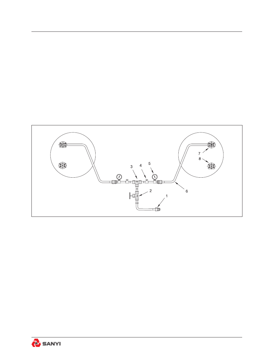
Less than 0.14 bar (2 lbf/in2) air pressure loss
in 15 minutes is satisfactory. If the air pressure
loss is greater than 0.14 bar (2 lbf/in2) in 15
minutes, rotate the wheel additionally to reseat
all seals and pressurise the brake assembly
to 2 bar (30 lbf/in2). If the brake assembly
again leaks more than 0.14 bar (2 lbf/in2)
air pressure in 15 minutes, loosen the wheel
retainer bolts, rotate the wheel to reseat the
seals, and tighten the bolts. Repeat the air
pressure test to be sure the seals are properly
seated, to prevent oil leaks.
Note
: Be sure to open and install only one
hydraulic line at a time to prevent loss of oil
from brake hydraulic oil tank. The vacuum
pump, installed during removal, cannot retain
oil in tank if more than one line is uncapped at
a time.
20. Remove the plugs and connect the
hydraulic pipe of service brake to the port ‘C’
according to the mark made during removing.
Refer to Fig.2.
21. Similarly, connect the pipeline of parking
Fig.18 Schematic diagram for pressure test of brake
1. Adaptor
5. Pressure gauge
2. Pressure regulator
6. Hose assembly
3. Tee piece
7. Flange plate (For ‘B’)
4. Switch valve
8. Flange plate (For ‘A’)
Rear Axle Assembly And Installation