SANY SRT95C Off-Highway Truck. Service Manual - page 10
 

  Index      Manuals     SANY SRT95C Off-Highway Truck. Service Manual


Search            copyright infringement  


Content      ..     8      9      10      11     ..


SANY SRT95C Off-Highway Truck. Service Manual - page 10


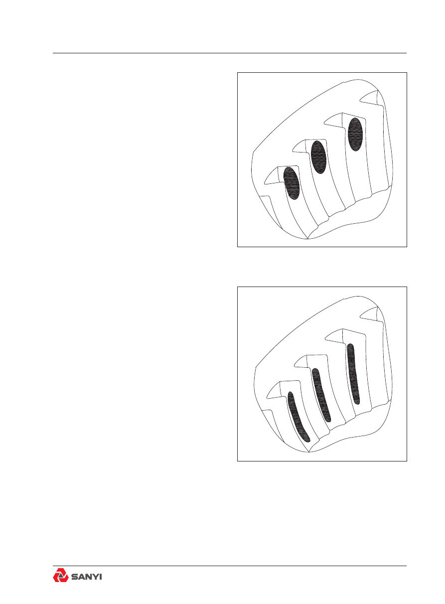
c. If the contact area is on the outer part of 
the driven spiral bevel gear teeth, see Fig.13, 
move driven spiral bevel gear toward pinion by 
turning bearing adjuster.

d. If the contact area is along the root of the 
driven spiral bevel gear teeth, see Fig.14, 
move the drive spiral bevel gear out by adding 
shims.

Fig.13 Excessive Backlash

Fig.14 Drive spiral bevel gear in Too Far - Add 
Shims

Rear  Axle Assembly And Installation

e. If the contact area is along the top edge 
of  the  driven  spiral  bevel  gear  teeth,  see 
Fig.15, move the drive spiral bevel gear in by 
removing shims.

Installation 

Numbers in parentheses refer to Fig.1.
1. Be sure truck wheels are chocked securely.
2. If the body is not already raised, raise body 
and install body prop pins. Refer to Section 
23, BODY AND MOUNTING. 
3. Clean mating surfaces of the banjo and 
main reducer and differential assembly with 
a  hydrocarbon  solvent  to  remove  dirt,  oil, 
grease, or other foreign matter. Wipe cleaned 
surfaces dry. Apply the sealant cord as follows: 
The adhesive side of the cord is applied to 
the banjo face, starting at the top, looping 

once around the first stud, then to the second 

stud, etc., ensuring not to overstretch the cord 
and that the loop between the studs will be 
on the inside of any of the main reducer and 
differential assembly extraction holes. Working 

all the way round finishing with an overlap at 

the top.  
4. Set screw (18) should already have been 
removed  from  the  top  of  the  differential 
housing and replaced with a lifting eye during 
removal. If not, remove set screw (18) from 
main reducer housing and replace it with a 
lifting eye. 
5. Position the main reducer and differential 
assembly under the truck in front of the banjo 
housing.
6. Install chain fall or come-a-long to the loop 
on the body just behind the hoist brackets. 
Attach the other end of the lifting device to the 
eye previously installed in the main reducer 
and differential assembly.
7.  Lift  the  main  reducer  and  differential 
assembly and carefully position it on the studs 
of the banjo housing.
8. Secure the main reducer and differential 
assembly to the banjo with the self locking 

Fig.15 Drive spiral bevel gears out Too Far - 
Remove Shims

Fig.16 Correct movement for adjustment

Moving the driven spiral bevel

gear outwards to correct the

situation in Figure 12

Moving the drive spiral bevel gear inwards to correct the situation in Figure 15

Moving the drive spiral bevel gear outwards to correct the situation in Figure 14

Move the driven spiral bevel

gear inwards to correct the

situation in Figure 13

Rear  Axle Assembly And Installation

nuts removed at removal. Tighten the nuts 

evenly in increments of 90 N•m (66 lbf•ft) to a 
final torque of 541 N•m (399 lbf•ft).

9. Replace the rear driveline, aligning marks 
made during disassembly. Refer to Section 19,
Rear driveline.
10. Install the axle shafts, then replace and 

secure the driving flange cover to the wheels. 

Refer to Section 3.1, Planetary assembly. 
11. Fill the drive axle, planetary reservoirs 
and main reducer anddifferential assembly 
with the proper grade and quantity of lubricant 

specified in Section 38.1, lubrication system.

Maintenance

Periodic inspection

Inspect regularly the flange yoke mounting 
bolts,  drive  spiral  bevel  gear  shaft  nut, 
bearing seat and bearing seat bolts and main 
reducer and differential assembly stud nuts 

for tightness. Tighten the stud nuts and flange 

bolts weekly until they 'set' or show that they 
no longer need tightening. Keep the nuts tight 
to reduce the possibility of main reducer and 
differential assembly or driveline failure due 
to excessive vibration or wear. Replace any 
mounting studs which have become stripped 
or broken.
Jack up the drive axle to 'test run' the main 
reducer and differential assembly and listen 
for noises which may indicate the need for 
adjustment or replacement of worn parts. 
When  doing  this,  lift  BOTH  wheels  off  the 
ground. Both wheel brakes should be free to 
allow both wheels to rotate at approximately 
the same speed.

Note

: Do not operate with only one wheel 

jacked up. Excessive operation in this manner 
will overheat the differential spider and cause 
galling or shearing of the spider trunnions and 
bearings.
If the main reducer and differential assembly is 
excessively noisy, it should be removed from 

Rear  Axle Assembly And Installation

the banjo and disassembled for inspection.

Lubrication

The main reducer and differential assembly 
is splash lubricated with an extreme pressure 
lubricant. The fill level plug is located in the 
centre rear of the banjo housing.
The main reducer and differential assembly 
should be checked and periodically drained 
and filled to the bottom of the fill-level hole, 
or to no more than 13 mm (0.5 in) below the 

fill level, with new lubricant as recommended. 

Refer  to  Section  38.1,  lubrication  system. 
When the lubricant is drained, remove any 
chips of steel particles that may be attached to 
the magnetic drain plug located in the bottom 
of  the  banjo  housing. After  draining  and 

refilling an axle, the planetary gearing should 

be checked after 10 hours of operation. 
1. Check the level in planetaries at oil level 
plug. If the oil level is low, add oil. This check 
point is a minimum check point only. If the oil 
level is above the check point, do not drain off 
oil.
2. Add oil if needed. The oil level is correct 

when oil flows from the lube level check plug 

in the banjo. These checks should be made 
every 10 hours until oil level in the differential 
is maintained.

SPECIAL TORQUE SPECIFICATIONS

FIG. NO.

ITEM NO.

ITEM NAME 

Torque

N•m

lbf·ft

1

2

Bolt

270

198

1

9

Bolt

270

198

1

21

Bolt

900

663

1

23

Bolt

74

54

1

28

Nut

900

663

1

29

Bolt

900

663

1

37

Bolt

580

428

Rear  Axle Assembly And Installation

Table of fault diagnosis

Condition

Reason

Remedy

Vibration

Broken gear teeth.

Replace the damaged gear.

The drive spiral bevel gear or bearing seat 
are excessively worn. 

Disassemble, correct or replace 
faulty part.

Continuous noise

Bearing worn.

Replace worn parts.

Gears damaged or worn.

Replace gears.

Noise on drive.

The drive and driven gears adjustment 
tight.

Adjust.

Noise on coast.

Bearing damaged.

Replace the bearing.

Loose the drive and driven spiral bevel 
gear adjustment.

Readjust it.

Excessive drive spiral bevel gear end play.   

Readjust it.

Noise on turns.

Worn axle shaft bevel gears or planetary 
bevel gears.

Replace the gear.

Worn or damaged spider bushings.

Replace the bearing.

Loss of lubricant.

Oil seals worn.

Replace seal.

Loose nuts.

Tighten nuts to correct torque.

Cracked housing.

Repair or replace housing.

Rear  Axle Assembly And Installation

1. Thread gasket

10. Snap ring

19. oscillation Stop

2. A-frame assembly

11. Bearing

20. Link nut

3. Bearing

12. Link

21. Washer

4. Gasket

13. Shaft

22. stud

5. Bolt

14. Washer

23. Breather

6. Steel wire

15. Washer

24. Screw plug

7. Washer

16. Bolt

25. Washer

8. Bolt

17. Bolt

26. Screw plug

9. Spacer

18. Washer

27. Axle housing component

Fig.1 Rear axle housing assembly

3.1.4 Rear axle housing assembly

Rear  Axle Assembly And Installation

Description and operation

The  rear  axle  assembly  consists  of  axle 
housing  assembly(27)  , A-frame  (2)  and 
Link(12). The axle housing assembly provides 
the housing for the differential and axle shafts 
which drive the wheels, and spindles to which 
the wheels are mounted. The axle housing 
assembly also connects the rear wheels to the 
chassis through A-frame (2), Link(12), and the 
rear ride cylinders.

Removal and disassembly 

See Fig.1 for the numbers in the brackets. 

warning

To prevent personal injury and property 

damage, be sure lifting equipment is of 

dequate capacity and properly secured to 

dothe job safely.

1. Remove the bolt (5) from A-frame assembly 
(2),  take  down  the  gasket  (4)  and  thread 
gasket (1). Then remove the bearing (3). If 

necessary, the grease fitting can be removed 

from the A-frame assembly (2). 
2. Remove the A-frame assembly (2) from the 
axle housing assembly (27) by Disassembly 
bolt (8) and washer (7). Before Disassembly, 
use the proper hoist device to lift up A-frame. 
3. Remove the bolt (17), Washer (18) and take 
down the oscillation stop (19). 
4.  Remove  the  bolt(16),  washer(15),  (14) 
and shaft(13). Take down the spacer (9) and 
link(12).  
5. Remove the Snap ring (10) and bearing (11) 
from the link (12). 
6. Remove the breather (23) from the axle 
housing assembly (27). 

Inspection

1. Clean all metal parts in a suitable solvent, 
using a brush to clean bearings. Dry all parts 

Rear  Axle Assembly And Installation

on a clean surface and allow bearings to dry 
naturally. Make sure parts are free from dirt. 
2.  Check  all  inner  and  outer  grooves  for 
cleanliness. Check components for cracks, 

scores, blemishes or burrs. Use a fine stone to 

smooth out defective areas. Replace any parts 
that show excessive wear. 
3.  Inspect  fittings,  plugs,  studs  and  their 
seating positions for thread wear. If threads 
in any of these parts are damaged, replace 
parts.
4. Check the bush, bearing and snap ring for 
wearing or deformation. Replace the defective 
parts and components. 
5. Replace the used gasket. 

Assembly and installation

See Fig.1 for the numbers in brackets. 

Note

: Tighten all fasteners without special 

torques  specified to standard torques listed 
in Section 38.2 'Standard bolt and nut torque 

specifications', unless it is otherwise noted. 

Note

: If heating of axle housing is required 

to assemble spindles and axle housing, axle 
housing  interference areas must cool to 66° C 
(150° F) maximum before welding. For welding 
spindles to axle housing preheat spindles and 
axle housing to 150° C (300° F) minimum in 
weld area and maintain during welding.
1. Install the washer (25), Screw plug (24) 
and Screw plug (26) onto the axle housing 
assembly (27).
2.  Install  the  breather  (23)  onto  the  axle 
housing assembly (27). 
3. Install the bearing (11) onto the link (12) and 

use the Snap ring (10) for fixing. Then, install 

the assembled link components onto the axle 
housing component (27) and install the spacer  
(9) and the articulated shaft (13). Then use the 

washer (14) , (15) and bolt (16) to fix the link 

(12) onto the axle housing components (27). 

4. Use the bolt (17) and washer (18) to fix the 

oscillation Stop (19) onto the axle housing 
component (27). 

Rear  Axle Assembly And Installation

5. Install the bearing (11) onto the A-frame 
assembly (2), and install the thread gasket 

(1) and gasket (4). Use the bolt (5) to fix them 

onto the A-frame assembly (2) and use steel 
wire (6) to lock the bolt (5). 
6.  Use  a  proper  hoist  device  to  install  the 
A-frame assembly (2) onto the axle housing 
components (27) and use the bolt (8) and 

washer (7) for fixation.  The tightening moment 
of bolt (8) is 3640 N•m.

warning

To prevent personal injury and property 

damage, be sure lifting equipment is of 

adequate capacity and properly secured to 

do the job safely.

Rear  Axle Assembly And Installation

Fig.1 General view of brake

3.1.5 Rear brake and installation

Rear  Axle Assembly And Installation

1. O-ring               

20. Bolt

38. Friction disc  

2. Driving wheel               

21. washer

39. Friction plate

3. Hardened washer        

22. Spring housing

40. Service brake piston

4. Bolt                   

23. Socket head screw

41. Bolt

5. O-ring              

24. O-ring

42. Mounting plate

6. Lockwire          

25. OG seal ring

43. Spring

7. Bolt

26. Guiding belt

44. Pin

8. washer              

27. Spring

45. Return pin

9. Outer seal housing       

28. Spring

46. D-ring

10. O-ring

29. Pin

47. D-ring

11. Seal ring            

30. Parking brake piston

48. Service brake piston housing

12. Dynamic seal assembly  

31. OD seal ring

49. Bleeder screw

13. O-ring

32. Guiding belt

50. Dust boot

15. Inner seal housing

33. Pin

51. Plug

16. O-ring

34. Housing

53. Stud

17. O-ring

35. O-ring

54. Locknut

18. Seal ring

36. Driving disc

19. Dynamic seal assembly

37. damper plate

Rear  Axle Assembly And Installation

Fig.2 Structure of brake

13. O-ring

43. Spring

47. D-ring

24. O-ring

44. Pin

49. Bleeder screw

33. Pin

45. Return pin

51. Plug

42. Mounting plate

46. D-ring 

52. Plug

port “A”

port “B”

port “D”

port “C”

port “D”

port “C”

Rear  Axle Assembly And Installation

Fig.3 Exploded view of brake assembly(Refer to Fig.1 and Fig.2 for the part names corresponding 
to the numbers)

Rear  Axle Assembly And Installation

Operation overview

Refer  to  Fig.1  and  Fig.2  for  numbers  in 
brackets.

Service brake

Note

: The  service  brakes  are  of  'Upright 

Design', i. E. requiring pressure to hold the 
brakes on. 
The rear service brake utilizes hydraulic force 
to slow or stop the driving wheel. When the 
pedal of foot brake in the cab is pressed down 
or the retarder control lever on the central 
operating console is operated and the retarder 
selector switch (if equipped) is turned into the 
position of rear disc brake, the hydraulic oil 
will be transmitted to the port ‘C’ on the rear 
disc brake, referring to Fig.2. The hydraulic 
oil entering into the port ‘C’ forces the service 
brake piston (40) against the brake disc pack 
consisting of the damper plate (37), friction 
disc (38) and friction plate (39).
The  friction  plate  is  clamped  between  the 
friction disc (38) and it is driven by the wheel via 
the driving wheel (2) and driving disc (36). To 
decelerate or stop the driving wheel, pressing 
force applied onto the brake disc component 
directly depends on the pressed level of brake 
pedal. 
When  the  service  brake  pedal  or  retarder 
control lever is released, the pressure asainst 
the service brake piston (40) is immediately 
relieved. The force of brake return spring (43) 
tightly against the head of the return pin (45) 
makes the return pin pull the piston (40) back 
to  the  original  position,  and  consequently 
the pressure against the brake disc pack is 
released.  

Parking brake

Note

:  The  parking  brake  is  of  'Inverted 

Design', i. E. requiring pressure to hold the 
brakes off. 
This  brake  is  operated  with  the  parking/
emergency brake control button mounted on 

Rear  Axle Assembly And Installation

the instrument panel. It is applied with spring 
force and released with hydraulic force. When 
the control button is released, the hydraulic 
oil enters into the port ‘D’, referring to Fig.2. 

And it flows into the oil passage in front of the 

parking brake piston (30) via the guide groove 
inside  the  brake  disc  housing  (34). At  the 
moment, the hydraulic oil will push the piston 
(30) to overcome the tension of springs (27 

and 28) and to remove pressure on the baffle 

(37). Consequently, the release of the brake 
disc component is maintained. If the control 
button is pressed, the oil pressure at the port 
‘D’ and that tightly against the parking piston 
(30) will be immediately released. The tention 
of springs (27, 28) recovers and forces against 
the damper plate (37) and disc pack consisting 
of friction disc(38)and friction plate(39). At the 
moment, the rotating friction plates clamped 
between friction discs are immediately pressed 
tightly, thus keeping the wheels from rotating. 

Removal

Refer  to  Fig.1  and  Fig.2  for  numbers  in 
brackets. 

Note

:  Before  the  disc  brake  assembly  is 

removed and disassembled, the wear extent of 

friction plates and baffles should be recorded 

referring to the specifications on measuring 
procedure and maximum allowed wear limit 
described in the 'Measuring procedure for disc 
brake assembly wear' under 'Inspection' in this 
section.  

Rear  Axle Assembly And Installation

warning

To prevent personal injury and equipment 

loss, it should be ensured that the hoist 

equipment has sufficient carrying capacity 

and  the  wheels  are  reliably  fixed  and 

chocked to enable safe operation. 

After the engine is shut down, the hydraulic 

oil still remains in the brake system. Before 

the brake system is operated, the pedal 

valve  should  be  continuously  operated 

until the pressure is completely released, 

so that severe personal injuries can be 

avoided. 

Use  extreme  caution  when  removing 

wheels. Specific operation procedure must 

be complied with as describedi in 'tyre and 

rim assembly'.

1. Place the truck in a flat place, apply parking 

brake, turn off the engine, turn the steering 
wheel in the two directions for several times, 
and  release  the  pressure  of  the  steering 
system. 
2. Continuously press down the brake pedal to 
release the brake system pressure. Chock the 
wheels and set the main switch of battery into 
the ‘OFF’ position. 
3. Remove the plug (51). Drain the cooling oil 
inside the disc brake assembly into a clean 
container and then reinstall the plug. 
4.  Remove  the  bleeder  screw  (49)  at  the 
bottom. Drain the brake hydraulic oil into a 
clean container. Then reinstall the bleeder 
screw. 

Note

: To reduce the loss of hydraulic oil during 

removing of oil pipe from the brake assembly, 
the air breather on steering and brake control 
oil tank can be removed in advance and the 
port can be connected to the vacuum pump to 
evacuate the air in the tank to vacuum of 0.5 - 
0.7 bar. 
5. Remove the brake cooling pipe from the 

Rear  Axle Assembly And Installation


Content      ..     8      9      10      11     ..