New Holland TX62, TX63, TX64 Plus, TX65 Plus, TX66, TX67, TX68, TX68 Plus. Operator's Manual - page 6
FIELD OPERATION
Units with flex header control printed circuit
Type
Header
Ground speed
Returns
Date & Time
• Language
• Reel speed synchro
•
Ground speed con-
•
Return cap constant
• Date & Time
gain
stant
• Chopper
•
Cal return
• Cal/Set Complete
• Header width
•
Cal/Set Complete
• Lateral float
•
Cal/Set Complete
Cal. lateral float
• Cal. header height
• Right return
• Flex header installed
• Units
• Cal/Set Complete
• Max engine RPM
• Cal. engine RPM
• Cleaning shoe
• Cal. concave
• Set contrast LCD
• Cal/Set Complete
4-106
SECTION
4
SPEED CONTROL MODULE
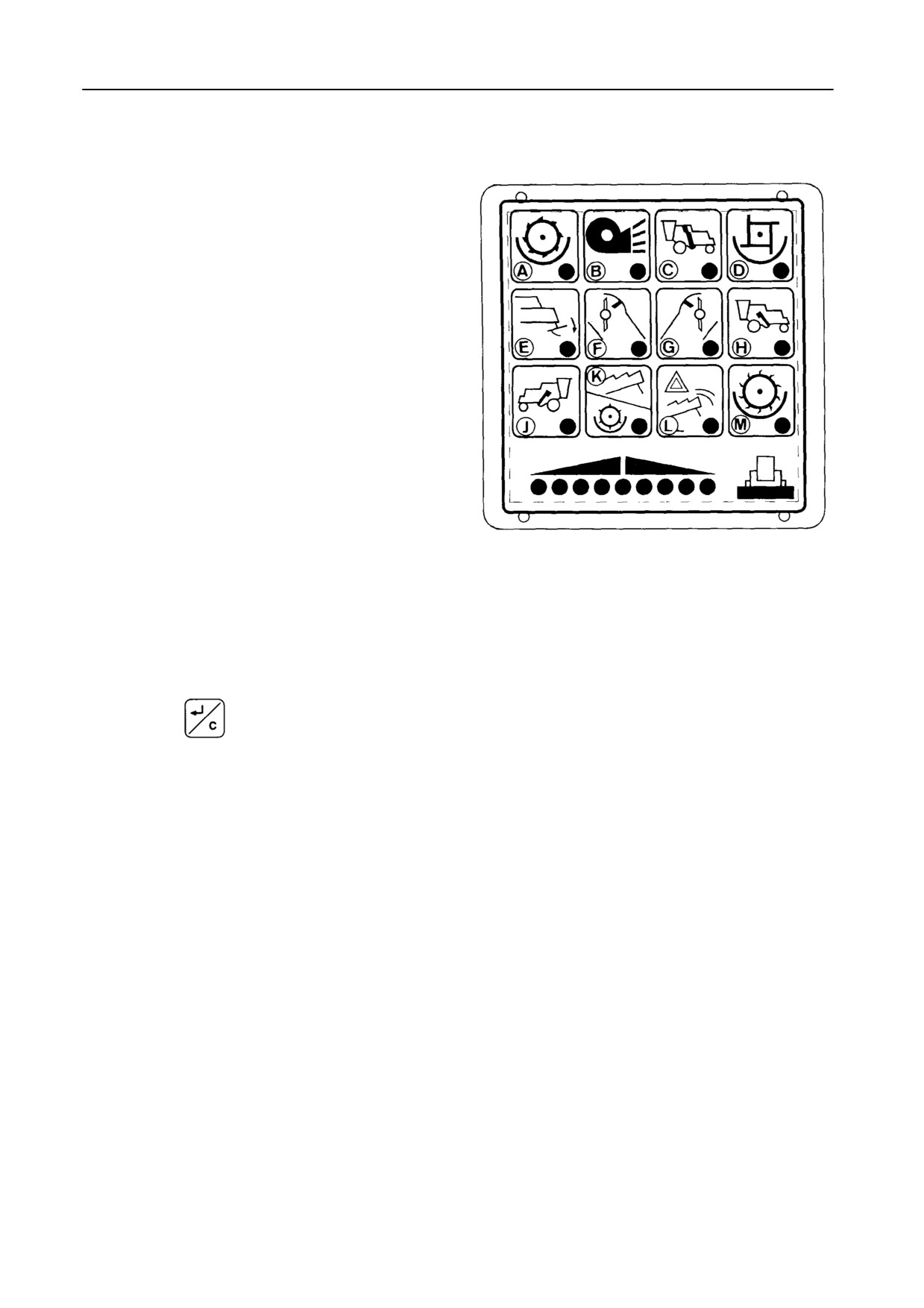
Channel Function
A
Threshing drum
B
Cleaning fan
C
Clean grain cross auger and elevator
D
Beater
E
Not used
F
Not used
G
Straw chopper
H
Returns auger (left-hand side
J
Returns auger (right-hand side)
K
Straw walkers
L
Straw walker blockage
M
Rotary separator
The determination of the maximum shaft speeds is
based on a 5 seconds measuring period.
51515
160
This period starts when:
- after ignition, the engine runs for the first time
at full throttle with the threshing mechanism
engaged, or
- each time the engine runs at full throttle with
the threshing mechanism engaged and pres-
sing the
key of the Infoview monitor.
This speed determination has to be performed each
time the threshing drum and/or cleaning fan
speed has been changed.
All warning lights will blink as long as the automatic
maximum shaft speed level determination is in opera-
tion (5 seconds).
If the combine is equipped with a straw chopper and
the chopper is off during the automatic maximum
shaft speed level determination, then the maximum
speed of the straw chopper is determined the first
time the chopper is engaged and the engine runs at
full throttle.
If a warning light starts to glow during operation and
the acoustic signal functions, the rpm of the corre-
sponding shaft is no longer correct (i.e. slowdown of
speed due to belt slippage, broken belt, etc.). In this
case, stop the machine immediately and investigate
the cause of the problem.
4-107

FIELD OPERATION
DIFFERENTIAL LOCK [if installed]
When operating in slippery or muddy ground condi-
tions the differential lock may be engaged to provide
better traction.
If one of the traction wheels starts spinning, immedi-
ately depress the differential lock pedal. Now both
traction wheels will turn at the same speed. Keep the
pedal depressed until the machine has passed the
obstacle.
Release the pedal to disengage the differential lock.
IMPORTANT:
S Do not make turns with the differential lock
pedal depressed.
S It may be necessary to slow down the com-
bine to allow engagement of the differential
lock.
STRAW CHOPPER [if installed]
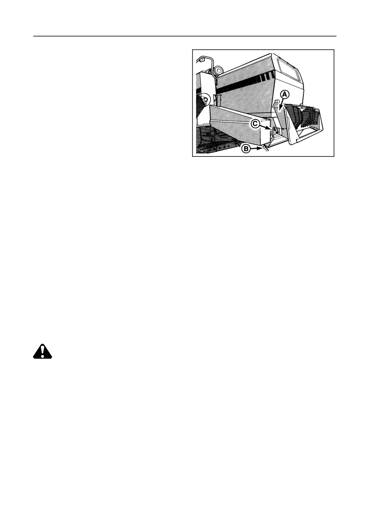
TRANSPORT POSITION -- Figures 161 and 162
For road transport, the chopper chute A must remain
in the operating position as shown, except when a
header trailer is attached. In this case, chute A should
be swung up completely.
To swing chute A up, disengage latch B, swing chute
A completely up as shown and lock latch C.
CHOPPING POSITION -- Figures 161 and 162
30351
161
1. To change to the operation position, disengage
latch C, swing chute A down and secure it with
latch B.
CAUTION:
Never swing the chute up during or just
after operation as the chopper continues
to rotate for considerable time.
Never engage the chopper with the chute
swung up!
4-108
SECTION 4
NOTE:
Latch B has two positions to secure the
spreader depending on the spread patterns re-
quired:
Position 1:
Narrow spread pattern
Position 2 :
Wide spread pattern
2.
Move the straw guiding plate to the front (i.e. the
chopping position) with lever D.
NOTE:
30346
The lever position is parallel to the plate posi-
tion.
162
3.
Adjust the straw chopper chute deflector plates
according to the header width.
Loosen bolts J and adjust with levers K.
SWATH-FORMING POSITION -- Figure 162
Move the straw guiding plate to the rear with lever D.
STRAW CHOPPER OPERATION
CAUTION:
Keep yourself and other people away
from the rear of the combine when the
straw chopper is engaged and operating.
Do not use the straw chopper near the
end of the field if there is a risk that crop
or stones can be projected onto a public
road.
With the engine running at idle speed and the thresh-
ing mechanism running, engage the chopper drive
with switch 44 (Section 2, Fig.10).
4-109
FIELD OPERATION
NOTE:
S With the engine and the threshing mecha-
nism running, straw guiding plate E in the
chopping position and the straw chopper
not yet engaged, the horn should sound!
S The chopper clutch is automatically disen-
gaged when the threshing mechanism is
disengaged.
CAUTION:
Always stop the engine before working
on the straw chopper.
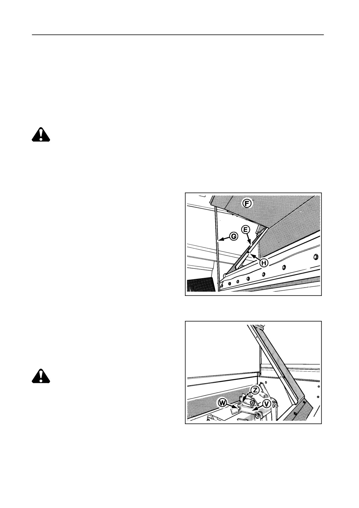
ACCESS TO THE STRAW CHOPPER ROTOR --
Figures 161 and 163
In case a blockage occurs or repairs are needed, ac-
cess to the straw chopper can be gained as follows:
1. Move the straw guiding plate E to the rear with le-
ver D (Fig.161).
2. Open latch H on both sides, pivot access door F to
the front and secure the door with rod G.
30353
163
CHOPPER KNIVES - Figure 164
The knives V on the chopper rotor have two cutting
edges.
CAUTION:
Do not operate with broken or damaged
knives. This is unsafe and the imbalance
may cause severe secondary damage to
the chopper and the combine.
30350
164
Whenever needed, the knives can be reversed or ex-
changed.
4-110
SECTION 4
Proceed as follows:
1. Remove bolt W, taking care not to lose the two
spacers and washers.
2. Turn the knife or install a new one.
3. Insert bolt W from the right-hand side (facing the
direction of travel).
4. Tighten nut Z to a torque of 64 Nm.
COUNTER KNIVES -- Figure 165
The counter knives must be set as follows:
Crop and/or
Counter knife
Posi-
condition
setting
tion
Dry straw
Fully advanced
1
Damp crop:
Towards the rear:
S Heavy straw
S Approximately
3
halfway
S Oil seed rape,
S Fully retracted
5
peas and beans
30347
Maize and sun-
Remove knives
--
165
flower
completely
(one by one)
To reposition the counter knives, loosen nuts A on
both sides, move the counter knives bar to the desired
position with lever B and retighten nuts A.
REPLACEMENT OR REMOVAL OF THE COUNT-
ER KNIVES -- Figures 165 and 166
To remove the counter knives, proceed as follows:
1. Set the counter knives in position 1 using bolts A
55149
on both sides.
166
2. Remove nine bolts U and cover T.
The counter knives can now be pulled out one by one
for replacement or removal.
IMPORTANT:
Do not remove the counter knife block itself
when chopping maize.
4-111
FIELD OPERATION
CHOPPING QUALITY -- Figure 165
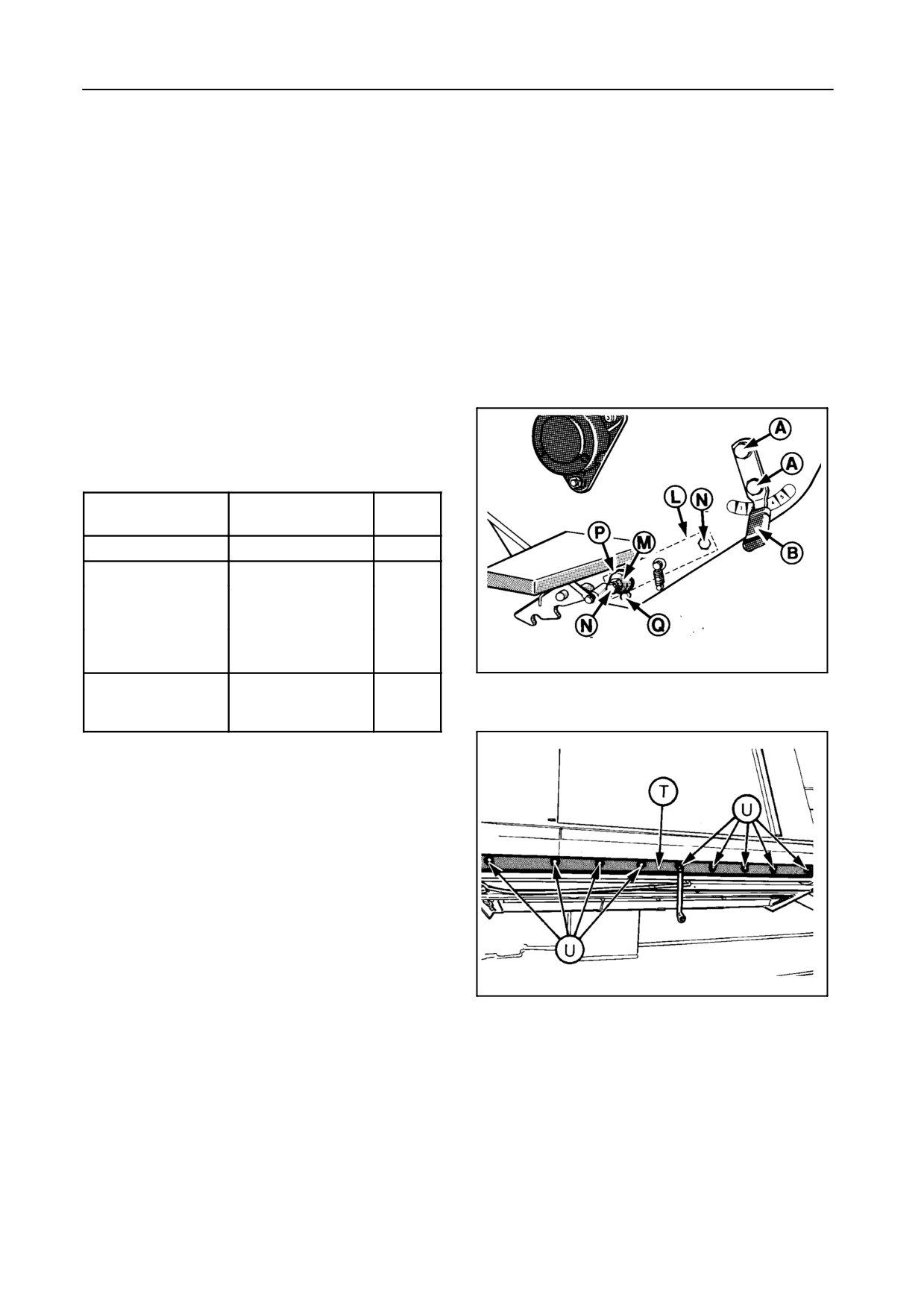
The chopping plate L can be set in three different posi-
tions with eccentric part M. The closer the plate L is
set to the rotor, the shorter the chopped straw will be.
Loosen bolts N on both sides, turn eccentric part M
into the desired position and make sure notch P is
onto stop Q.
Tighten bolts N.
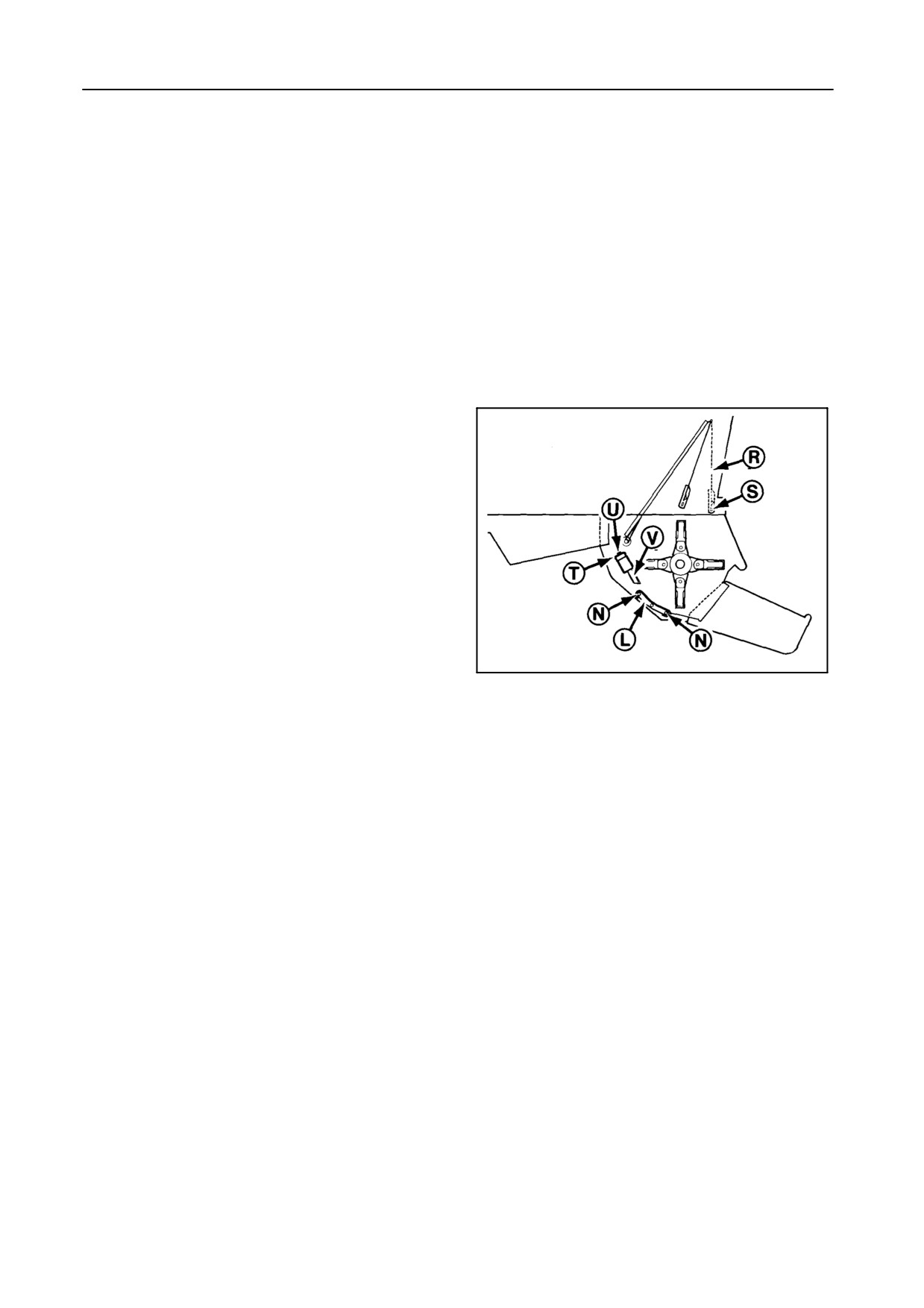
CHOPPING MAIZE -- Figure 167
For chopping maize, proceed as follows:
1. The rotor speed must be reduced by installing a
larger pulley onto the hub of the rotor shaft. This
pulley is part of the straw chopper slow down kit
which is available as an accessory.
2. The chopping plate L must be turned 180_ so that
the flat side is on the inside.
Remove bolts N on both sides and turn chopping
30354
plate L.
167
3. Set rear plate R into the forward position using
bolts S on the inside.
4. Loosen bolts U and remove cover T. Remove
counter knives V one by one.
STRAW CHOPPER CLUTCH
When the clutch fails it must be repaired or replaced
as soon as possible. Legislation no longer allows to
temporarily lock the clutch in the engaged position be-
cause of the safety hazard created when the straw
chopper knives rotate whenever the engine is running
(even with the threshing mechanism disengaged).
4-112
SECTION 4
CHAFF SPREADER [if installed] -- Figures
168 to
173
OPERATING POSITIONS
The chaff spreader has four positions:
S Forward position: Spreading position
S Vertical posiiton:
- Control of grain losses
- Maize harvesting position
43204
S Rear position: Setting of sieve position
168
S Swing-up position to remove the sieves.
IMPORTANT:
The rear position and swung-up position are
not allowed during field operation.
The vertical position is shown in Figure 168.
CAUTION:
When the combine engine is running, the
chaff spreader is automatically engaged
when the threshing mechanism is enga-
ged.
Always disengage the threshing mech-
43206
anism and stop the engine before work-
169
ing on the chaff spreader.
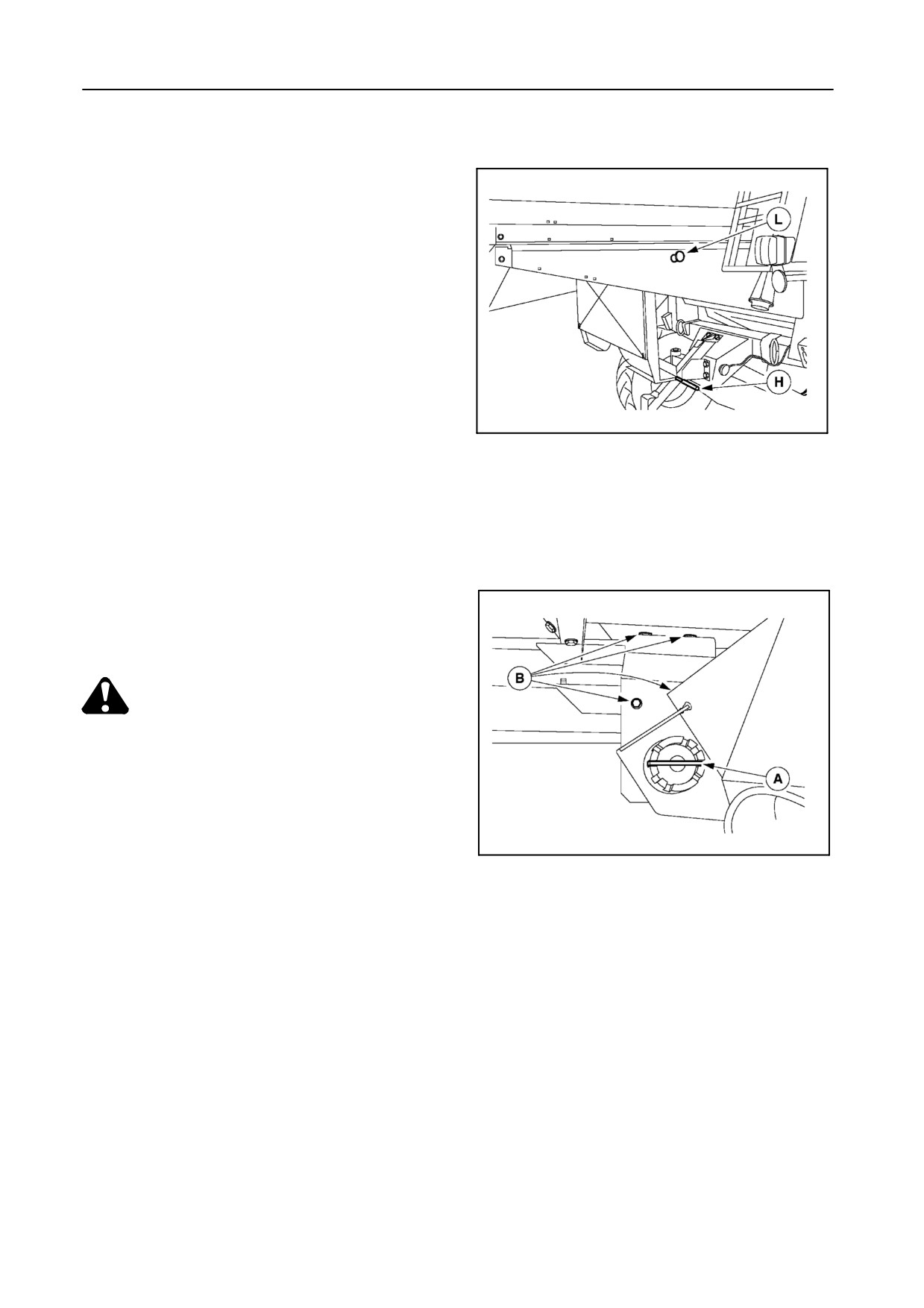
To change position, proceed as follows:
1. Press spring-loaded knob L.
2. Move the chaff spreader into the desired position
with handle H.
3. Release spring-loaded lever L and move the chaff
spreader until lock A jumps into the groove.
4-113
FIELD OPERATION
It is possible to adjust the distance between the
sieves and the chaff spreader in the forward postion.
Four distances are available.
To change the distance, proceed as follows:
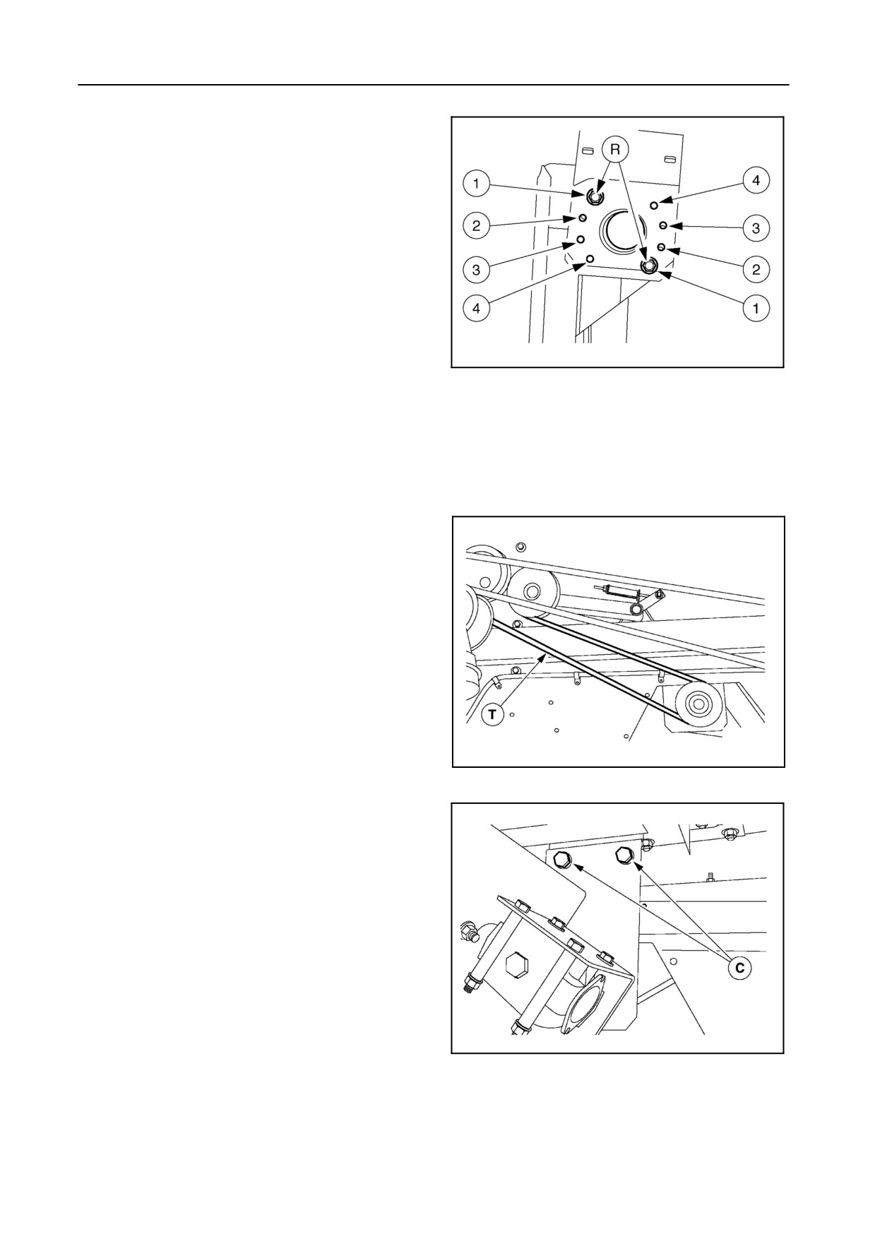
1. Set the chaff spreader into the vertical position.
2. Remove two bolts R.
54779
3. Reinstall bolts R into position 1-1, 2-2, 3-3 or 4-4
170
(position 1-1 gives the closest position between
the sieves and the chaff spreader).
4. Set the chaff spreader into the forward position.
DISENGAGING AND REMOVING THE
SPREADER
When not using the chaff spreader or when harvest-
ing maize, remove belt T and leave the chaff spreader
in the vertical operating position.
IMPORTANT:
During field operation, the chaff spreader must
never be located in the swung-up position,
43207
even when it is not being used, as chaff accu-
171
mulation under the straw walkers may occur!
If too much chaff builds up, the spreader can be re-
moved.
Proceed as follows:
1. Remove belt T (Fig.171).
2. Remove knob L (Fig.168).
3. Remove four bolts B (Fig.169) on the right-hand
43203
side.
172
4-114
SECTION 4
4. Remove two bolts C (Fig.172) on the left-hand
side.
CAUTION:
The chaff spreader is heavy, use a lifting
device of adequate capacity.
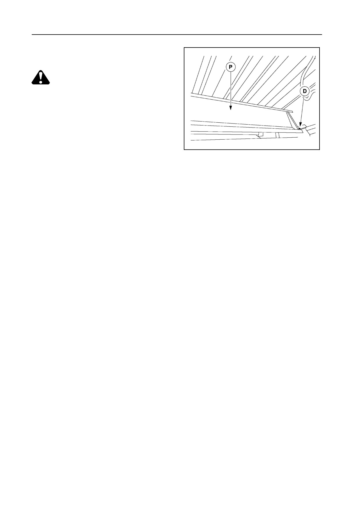
5. Remove chaff spreader plate P by loosening bolts
D on both sides.
43210
173
AIR CONDITIONING
The air-conditioning system must only be operated
after the combine engine is warm and the interior of
the cab is 15° C minimum.
ATTENTION:
Ignoring this precaution may cause damage to
the system.
NOTE:
If the ambient temperature is around 15° C,
the low pressure warning light may light up.
This warning is generated by the low ambient
temperature and may be ignored.
4-115
FIELD OPERATION
COMBINE PERFORMANCE CHECKS
KILL-STALL
11. With all previous factors considered, readjust the
combine.
The only way to accurately check the performance of
the combine is to complete a ‘‘kill-stall’’.
NOTE:
Make only one adjustment at a time so that any
1. Operate the combine in a section of the field that
change in combine performance can be
best represents the overall crop. Be sure the
attributed to that particular adjustment.
combine is at least 100 m into the crop and travel-
ling at the normal operating ground speed.
2. Press the top part of the engine reset switch 51
(section 2, Fig.10), apply the brakes gently and
allow the complete combine to stop. This will
PERFORMANCE INDICATORS
leave crop material as it was during actual har-
vesting.
There are four indicators which will tell you how well
the combine is performing. These four indicators are:
3. Disengage the threshing and header engage-
ment system clutch, move the hydrostatic speed
S Grain tank sample
control lever to neutral, move the throttle control
to the low position and restart the engine immedi-
S Distribution of material on the grain pan and upper
ately. This prevents the engine from overheating
sieve
and from being damaged. Allow the engine to
slow idle for five minutes before stopping the en-
S Type and amount of returns
gine.
S Losses
4. Check the grain tank sample for complete thresh-
ing, cleanliness and damage.
By correctly reading these indicators and being famil-
iar with the combine, you can make the necessary ad-
5. Walk out in front of the header and check the crop
justments to correct any problem and improve the
loss before the header has contacted the crop
overall combine performance.
(preharvest loss).
6. Check the crop loss in an area where only the
header has travelled (header loss).
7. Check the distribution of material on the grain
pan.
8. Check the type, amount and distribution of mate-
GRAIN TANK SAMPLE
rial on the sieves.
A large amount of trash in the grain tank indicates the
9. Check the type and amount of returns.
crop is being overthreshed and/or the cleaning fan
speed is too slow. The first step to correct this prob-
10. Check the total loss in a 60 cm wide area across
lem is to increase the concave clearance and/or re-
the width of the cleaning shoe. Subtract prehar-
duce drum speed. This reduces or eliminates the ma-
vest and header losses to determine the machine
terial break-up caused by overthreshing. Then in-
loss.
crease the cleaning fan speed if the trash is heavier
Use a drop screen to check the machine loss di-
than the grain or close the upper sieve if the trash is
rectly.
larger than the grain.
4-116
SECTION 4
Cracked or damaged grain can be caused by a con-
The front third of the upper sieve should be com-
cave setting that is too close to the drum. Increase the
pletely clean. The middle third should have some
concave clearance and then reduce the drum speed
grain but mostly residue. The rear third of the upper
to correct the problem.
sieve should have only residue.
Bunch feeding can cause grain damage in the straw
If there is some grain on the rear third of the upper
elevator. An incorrect straw elevator chain tension
sieve, returns will be increased and there is a possibil-
can also cause grain damage.
ity that grain will ride out the back of the combine.
Open the upper sieve to allow more of the grain to fall
Excessive returns will contribute to grain damage due
onto the lower sieve.
to the additional pass(es) the grain must take through
the drum/concave area. Plugged concaves can
If the material on the upper sieve is broken into small
cause grain damage because the free grain cannot
pieces, the crop is being overthreshed. This can plug
get out of the concave area.
the upper sieve and cause high losses. Increase the
concave clearance and/or reduce drum speed to de-
Loose elevator chains can also cause grain damage.
crease the threshing action.
It is important to maintain the proper tension on these
chains.
Unthreshed heads indicate the drum speed should be
increased and/or the concave clearance should be re-
Unthreshed material in the grain tank can be caused
duced. Unthreshed heads can also be caused by
by underthreshing or the lower sieve that is opened
worn rasp bars and worn concaves.
too wide. Increase the drum speed and reduce the
concave clearance as needed to correct the problem.
Also close the lower sieve slightly to obtain a cleaner
grain tank sample.
RETURNS SAMPLE
It is normal for the returns sample to contain a few un-
threshed heads. The purpose of the returns system is
to return unthreshed heads to the threshing area for
GRAIN PAN / UPPER SIEVE DISTRIBUTION
another pass. However, a large quantity of un-
threshed heads indicates the concave clearance is
The distribution of material on the grain pan affects
too great.
the distribution of material on the sieve. The distribu-
tion on the grain pan should be level to slightly higher
If the returns sample contains a large quantity of
directly under the drum and taper slightly towards
clean grain, the cleaning fan speed should be re-
both sides.
duced and/or the lower sieve should be opened more.
4-117
FIELD OPERATION
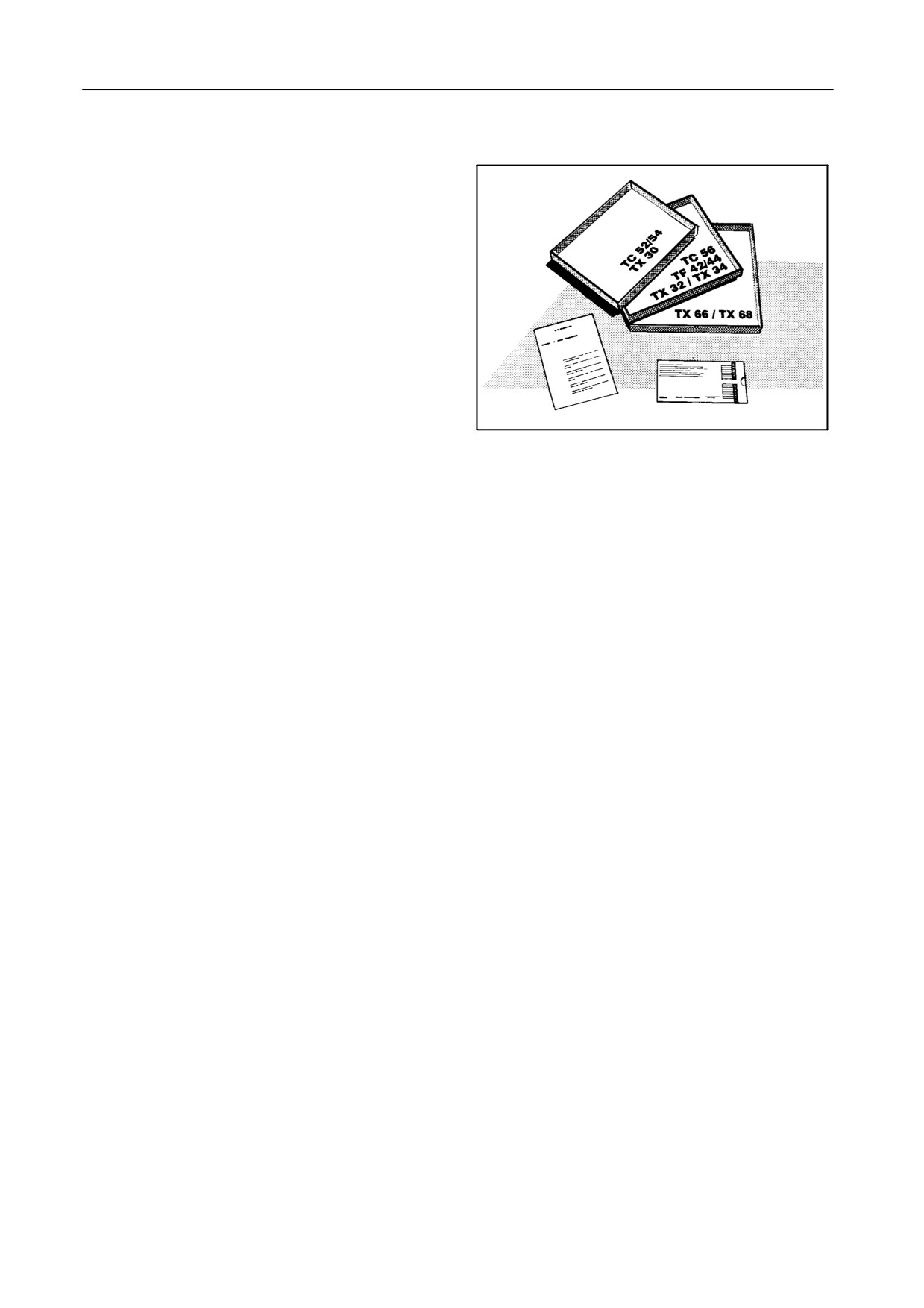
GRAIN LOSS MEASURING KIT -- Figure 174
(Part number 80456667 - can be ordered from your
local dealer).
LOSSES
Losses may occur at different stages:
a)
Pre-combining losses (i.e. losses found in front
of the combine) are usually caused by adverse
20956
weather conditions, poor crop conditions and crop
174
maturity.
b)
Header losses: (i.e. losses found behind the
header and outside of the tyres) may be caused by
improper header adjustments.
c)
Leakage losses may be caused by damaged
seals or holes in bottom auger covers.
d)
Shoe losses may be caused by a poor sieve ad-
justment, or low cleaning fan speed, or when
working on slopes (exceeding the capacity of the
sieve levelling system [if fitted]).
e)
Fan losses are caused by an excessive cleaning
fan speed.
f)
Straw walkers losses. These can be unthreshed
ears (underthreshing) or grains, due to poor ad-
justment of drum and concave or excessive
ground speed.
4-118
SECTION 4
HOW TO USE THE KIT
Total losses caused by the machine:
1. Walk beside the combine in operation and throw
Lt = (b + c) + (d + e) + f - a
the tray under the centre of the cleaning shoe.
CAUTION:
When checking losses, the straw chop-
per or spreader drive must be disenga-
Functional losses
ged.
Lf = d + e + f
The person throwing the tray must make
sure he cannot be trapped by the steering
wheels.
To check functional losses [cleaning shoe, fan and/
or straw walker loss(es)], the grain loss measuring kit
2. After the combine has passed, take the tray and
can help in determining loss levels.
count the grains in the tray.
3. Use the slide calculator (Figure 175) to convert the
quantity of grains into kilogrammes per hectare.
KIT CONTENTS
The grain loss measuring kit contains:
S
3 trays (according to machine width)
S A slide calculator
S An instruction booklet
4-119
FIELD OPERATION
50680
175
Example:
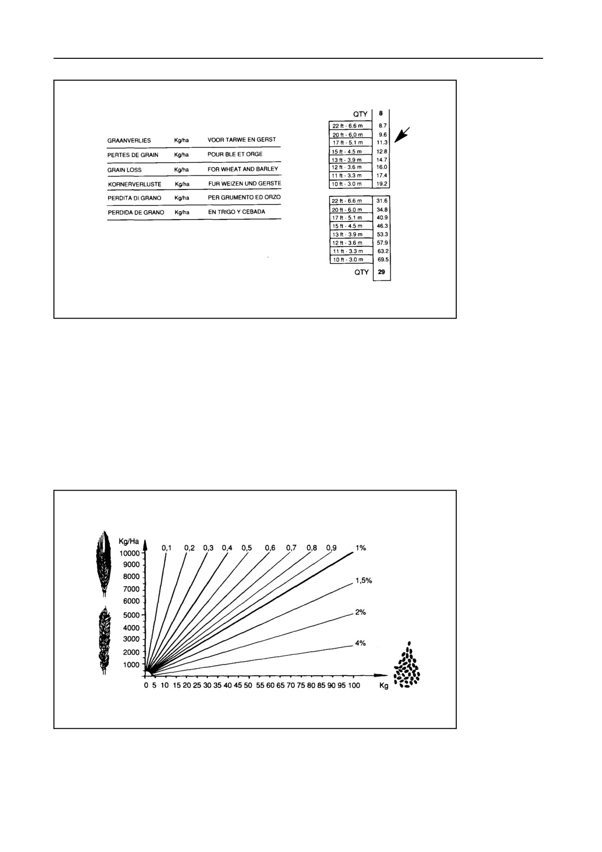
Model TX66 with 17 ft (5.10 m) grain header operating
in wheat.
Refer to Figure 175:
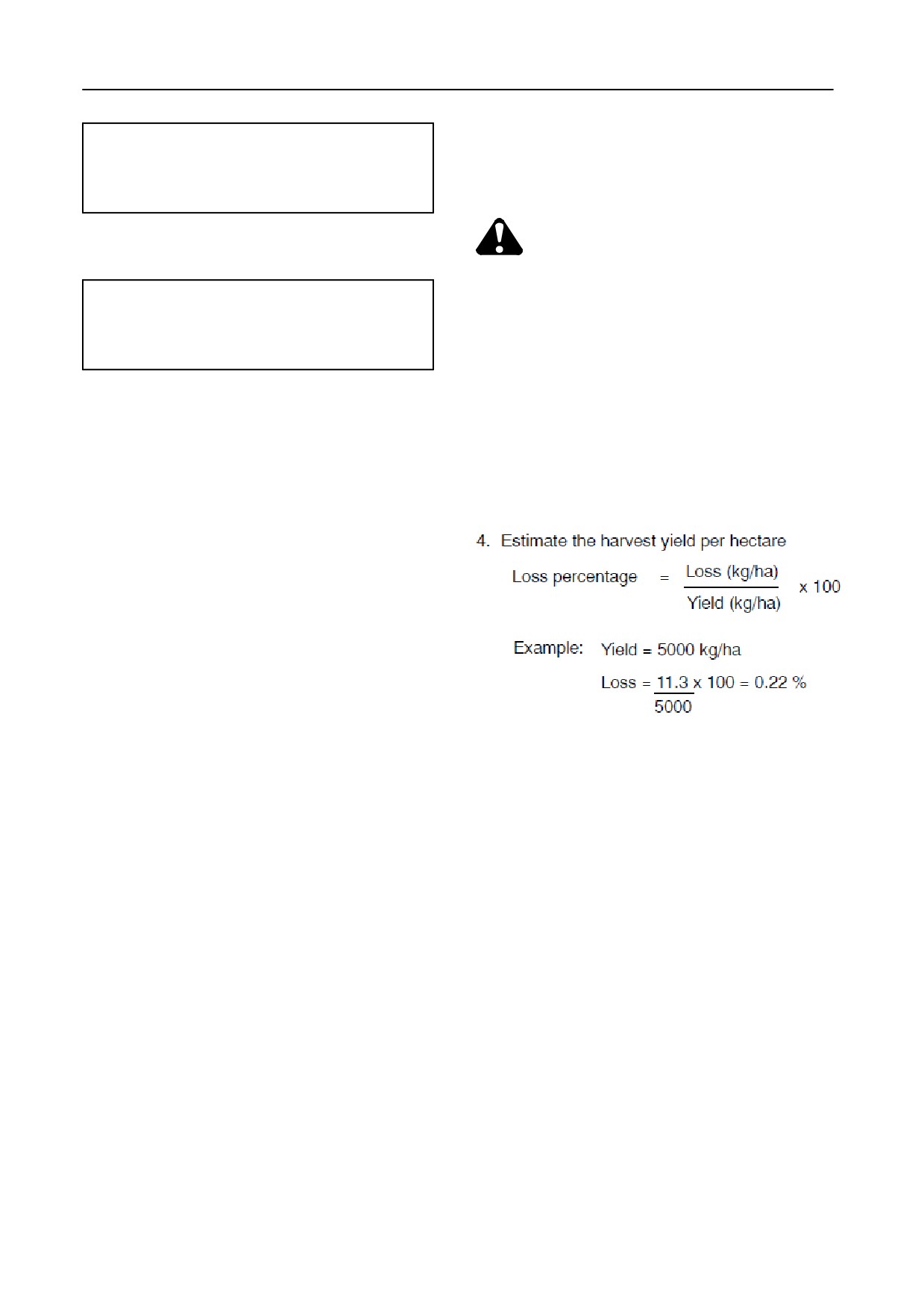
8 grains in the tray means a loss of 11.3 kg/ha.
The diagram in Figure 176 will help you to determine the loss percentage.
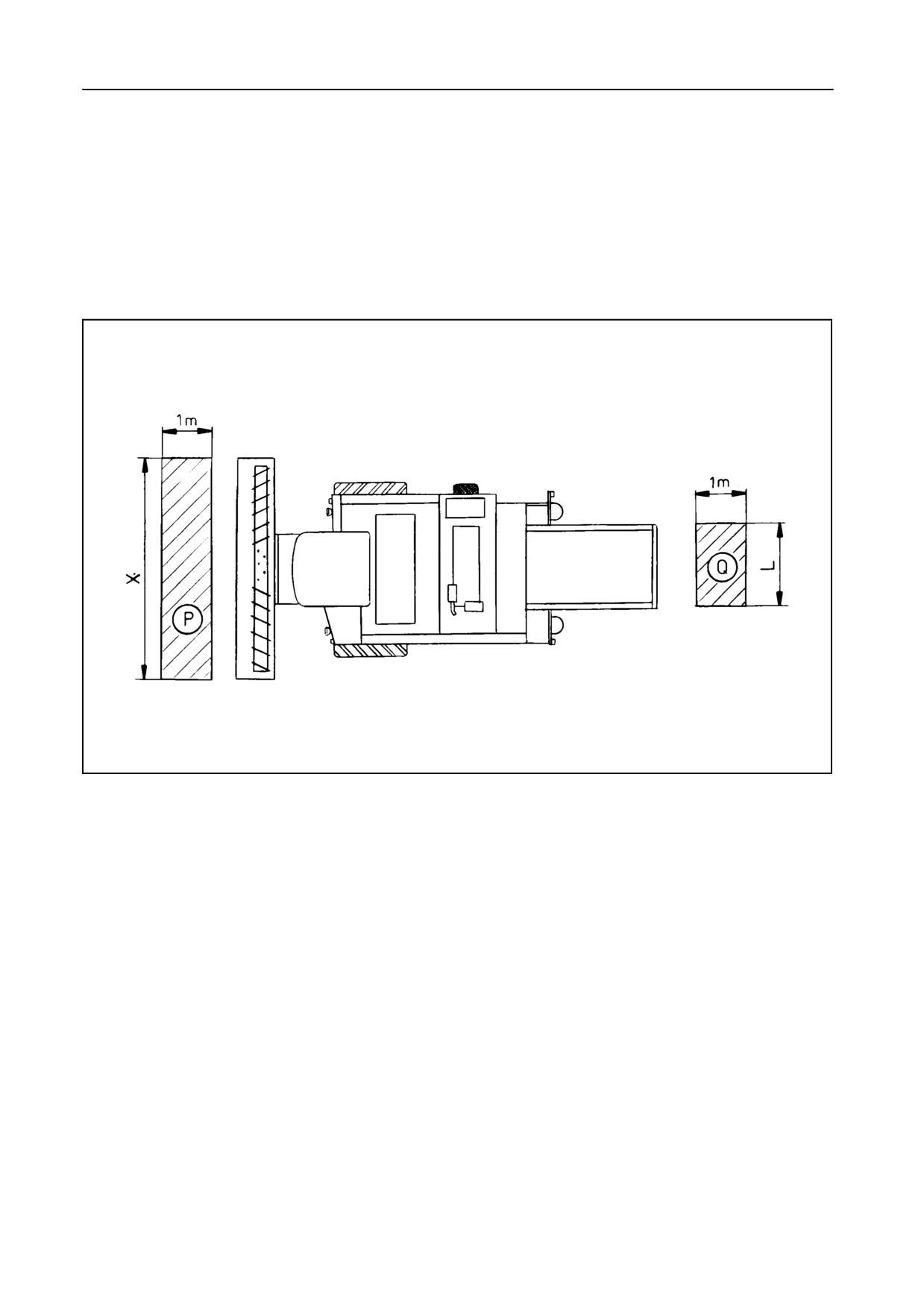
50679
176
4-120
SECTION 4
HOW TO OBTAIN AN IDEA ON LOSS LEVEL --
Figure 177
Example:
Model TX66 with 17 ft (5.10 m) grain header operating
in wheat.
Average yield: 5000 kg/ha.
50399
177
-- Surface P = surface being harvested:
-- Considering the average weight of wheat being
1 meter multiplied by X (header width) = 5.1 m2.
23,000 grains/kg, this means: 586 grains in sur-
face Q (1 % loss level!).
-- Surface Q = surface of the material being cut in
surface P, behind the machine (i.e. swath):
-- An average human hand with spread fingers cov-
1 meter multiplied by Y (drum width, i.e. 1.5 m) =
ers a surface of approximately 0.03 m2. This
1.5 m2.
means that, if the grain loss is evenly spread, 18
-- Consider a loss level of 1% = 50 kg/ha or 5
grains can be found underneath the hand, repre-
grams/m2 crop.
senting 1% grain loss for a 5000 kg/ha yield.
Surface Q will then contain the functional losses
(i.e. cleaning shoe, straw walker, fan) of surface P
(5.1 m2), being 5 x 5.1 = 22.5 grams.
4-121
SECTION 4
SUMMARY OF THE MACHINE SETTINGS FOR DIFFERENT CROPS
Concave position
TYPE OF
Optional
Drum
•
TX62-63
equipment
speed
CROP
•
TX64PLUS to TX68PLUS
required
•
Clearance at 2nd and
8th bar
•
De-awning plates
•
2nd position
WHEAT
700-1100 rpm
•
10 mm
•
Rasp bar in front of
concave (varieties
•
10/10 mm
with white caps)
•
1st or 2nd position
•
De-awning plates
•
10 mm
BARLEY
800-1000 rpm
(some varieties)
•
10/10 mm
•
1st or 2nd position
•
Idem Barley
WINTER
800-1000 rpm
•
10 mm
BARLEY
Close de-awning
•
10/10 mm
plates, if necessary.
•
2nd or 3rd position
RYE
1000 rpm
•
10 mm
•
10/10 mm
•
2nd or 3rd position
TRITICALE
700-1000 rpm
•
10 mm
•
10/10 mm
•
2nd position
•
10 mm
OATS
800-1000 rpm
•
10/10 mm
•
Stone trap cover plate
•
Antiwrap shields on
•
4th position
straw elevator upper
RICE
650-1000 rpm
shaft
•
20 mm
•
Spike tooth bars
and concave
•
20/25 mm
•
Tracks
•
Maize header
•
7th position
400-500 rpm
•
Maize concave
MAIZE
•
25 mm
In dry conditions, use
•
Smooth roto-
a speed reducer
•
25/30 mm
thresher covers
(250-400 rpm)
•
1st or 2nd position
Antiwrap shields on
FLAX
800-1000 rpm
•
10 mm
straw elevator upper
shaft
•
10/10 mm
4-123

FIELD OPERATION
Sieve openings
Beater
Rotary
Fan
equipment
separator
speed
speed
Upper
Lower
Presieve
Blades
760 rpm
900 rpm
Open
3 -- 5 mm
6 mm
Blades
760 rpm
700 rpm
10 -- 12 mm
3 -- 5 mm
6 mm
Blades
760 rpm
750 rpm
10 -- 12 mm
3 -- 5 mm
6 mm
Blades
760 rpm
700 rpm
10 -- 12 mm
3 -- 5 mm
6 mm
Blades
760 rpm
700 rpm
10 -- 12 mm
3 -- 5 mm
6 mm
Blades
760 rpm
550-600 rpm
10 -- 12 mm
3 -- 5 mm
6 mm
Teeth
760 rpm
650 -700 rpm
10 -- 12 mm
3 -- 5 mm
6 or 9 mm
(10 rakes)
Maize sieve
Hart Carter
Teeth
400 rpm
800-920 rpm
(Hart Carter
9 or 12 mm
1-1/8’’sieve
(5 rakes)
1-5/8’’)
10 mm
12 mm
Blades
760 rpm
500-550 rpm
4 -- 7 mm
2 -- 4 mm
3 or 6 mm
4-124
SECTION
4
Concave position
TYPE OF
Optional
Drum
•
TX62-63
equipment
speed
•
TX64PLUS to TX68PLUS
CROP
required
•
Clearance at 2nd and
8th bar
• Graepel sieve ex-
•
3rd to 6th position
tension
RAPE SEED
600-650 rpm
•
24 mm
• Smooth roto-thresher
covers
•
24/24 mm
•
3rd position
700 rpm
•
17 mm
GRASS SEED
•
17/19 mm
•
Perforated auger covers
•
4th to 6 th position
•
Smooth roto-thresher
•
Beans:
27 mm
BEANS/PEAS
covers
400-450 rpm
27/27 mm
•
Perforated straw eleva-
Peas:
20 mm
tor bottom
20/20 mm
•
1st position
Close de-awning
CLOVER
Maximum
•
3 to 5 mm
plates, if necessary
•
3 to 5 mm, paral-
lel with drum
•
2nd position
Special crop lifters
SORGHUM
800 rpm
•
10 mm
on the header
•
10/10 mm
•
4th to 6th position
SAFFLOWER
300-550 rpm
•
27 mm
•
27/27 mm
•
Superflex header
•
Smooth roto-thresher
•
4th or 5th position
covers
SOYA BEANS
Minimum
•
20 mm
•
Maize concave
•
Perforated auger covers
•
20/25 mm
•
Perforated straw
elevator bottom shaft
300-550 rpm
•
4th to 6th position
SUNFLOWER
Smooth roto-thresher
In dry conditions,
•
27 mm
covers
speed reducer is
necessary
•
27/27 mm
•
3rd to 5th position
•
10 to 25 mm
MUSTARD
600-650 rpm
•
10/10 mm to
25/25 mm
•
2nd position
BUCKWHEAT
600 rpm
•
10 mm
•
10/10 mm
4-125

FIELD OPERATION
Beater
Rotary
Sieve openings
Fan
equipment
separator
speed
speed
Upper
Lower
Presieve
450 -- 500 rpm
Blades
400 rpm
8 mm
2 mm
6 mm
Eccentric shaft
low rpm
Blades
760 rpm
400
5 mm
3.5 mm
6 mm
or teeth
Teeth
400 or 760 rpm
Beans: 15 mm
Maximum
8 -- 12 mm
9 or 12 mm
Grate in lower
Peas:
10 mm
(5 rakes)
position
Blades
760 rpm
Minimum
8 mm
2 to 3 mm
3 mm
Blades
760 rpm
750 - 800 rpm
10 mm
5 m m
3 or 6 mm
Blades
400 rpm
550 -700 rpm
12 mm
7 mm
6 or 9 mm
Maize sieve
Blades
400 or 760 rpm
750 rpm
Hart Carter
Hart Carter
9 or 12 mm
1-5/8’’
1-1/8’’
10 mm
6 mm
400 rpm
If losses occur:
Blades
600-650 rpm
760 rpm
10 -- 12 mm
6 -- 7 mm
12 mm
Grate in lower
position
450 - 500 rpm
Blades
400 or 760 rpm
8 -- 10 mm
0 -- 5 mm
3 or 6 mm
Eccentric shaft
low rpm
Blades
400 or 760 rpm
550 rpm
12 mm
8 mm
6 mm
4-126
SECTION 5
ADJUSTMENTS AND MAINTENANCE
nent described in this Section.
CAUTION:
Always stop the engine, unless other-
wise instructed, before checking and/or
adjusting any belt, chain or other compo-
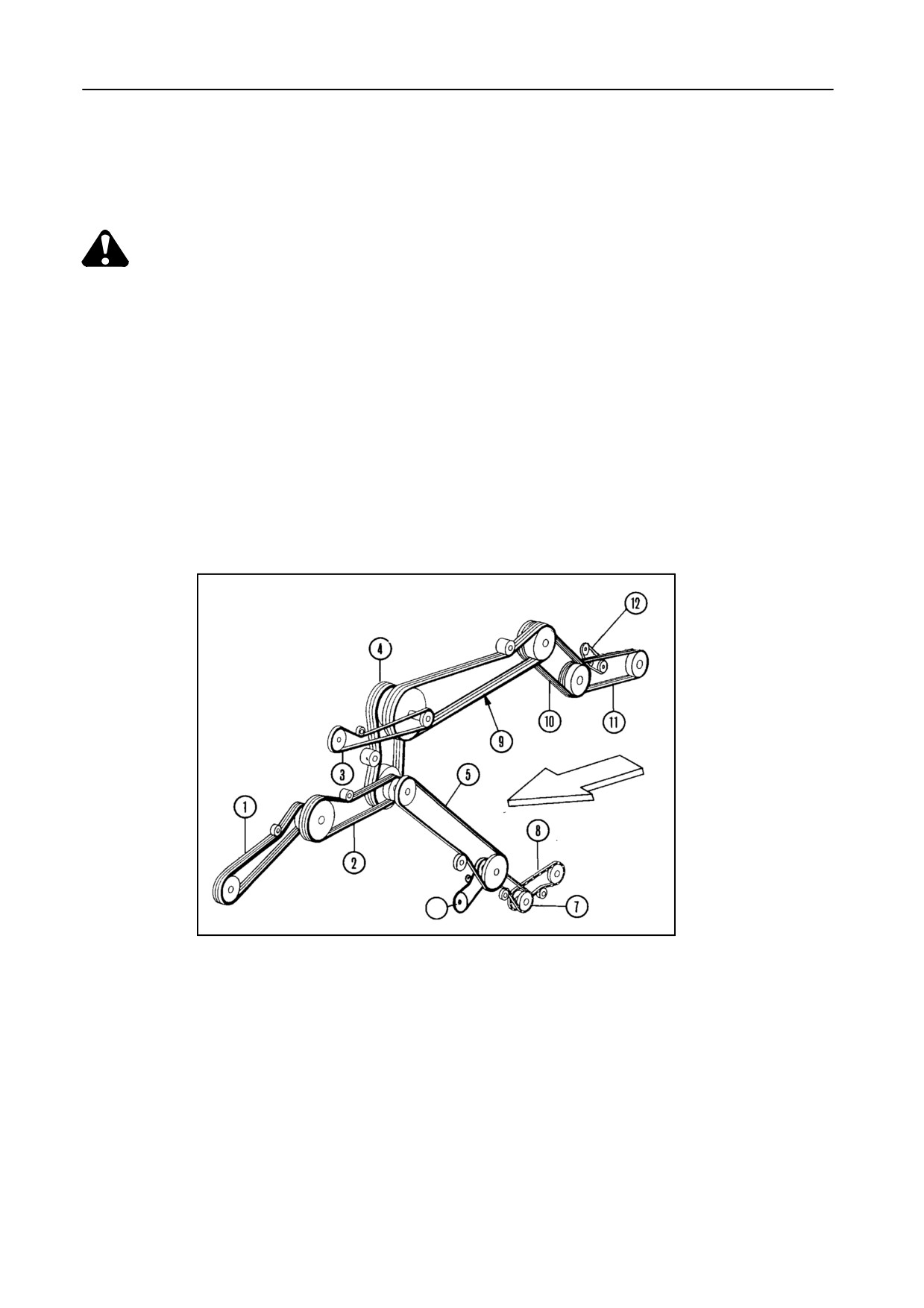
DRIVE BELTS AND CHAINS
[left-hand side] -- Figure 1
IMPORTANT:
Daily check all belt and chain tensions to en-
sure optimum operation.
A maintenance schedule is mapped out at the
end of this Section.
6
30221
1
1
Header drive belt
8 Returns auger drive chain
2
Straw elevator and header engaging belt
9 Main drive belt
3
Unloading system engaging belt
10 Straw chopper front drive belt [if fitted]
4
Main engaging belt
11
Straw chopper rear drive belt [if fitted]
12 Chaff spreader drive belt [if fitted]
5
Cleaning shoe drive belt
13 Chaff spreader discs drive belt (not shown)
6
Eccentric shaft drive
Fixed cleaning shoe: belt drive
NOTE:
Self-levelling cleaning shoe: p.t.o. drive
Most belt idlers are spring-loaded and are fit-
7
Roto-threshers and returns cross auger drive
ted with an indicator plate to indicate the cor-
chain
rect belt tension.
5-1
ADJUSTMENTS AND MAINTENANCE
1
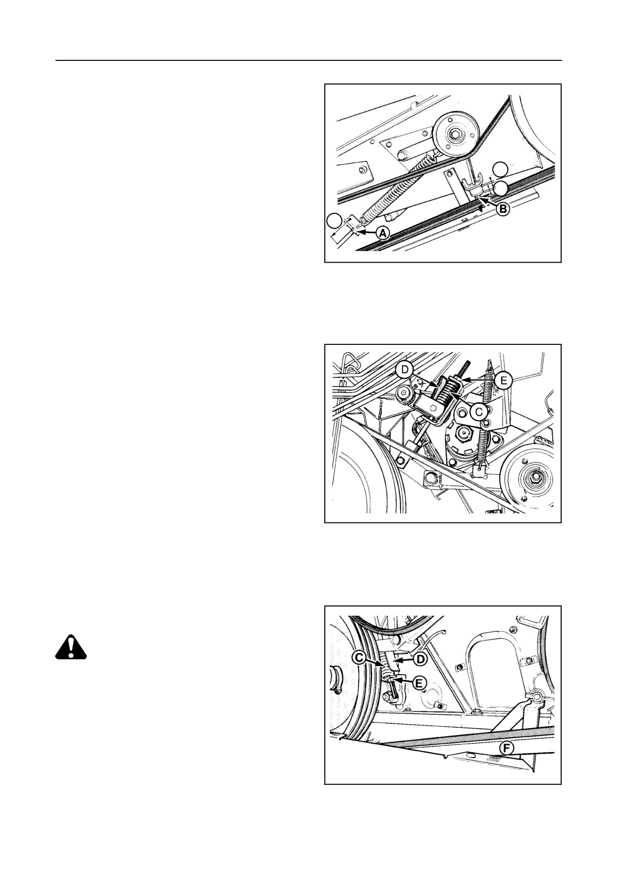
HEADER DRIVE BELT -- Figure 2
Correct belt tension:
X = 100 mm for 1HC belt
X = 155 mm for 4HB belt
Adjust with nuts A.
Y
Y should be 0 mm. Adjust with nuts B.
Y
X
30215
2
2
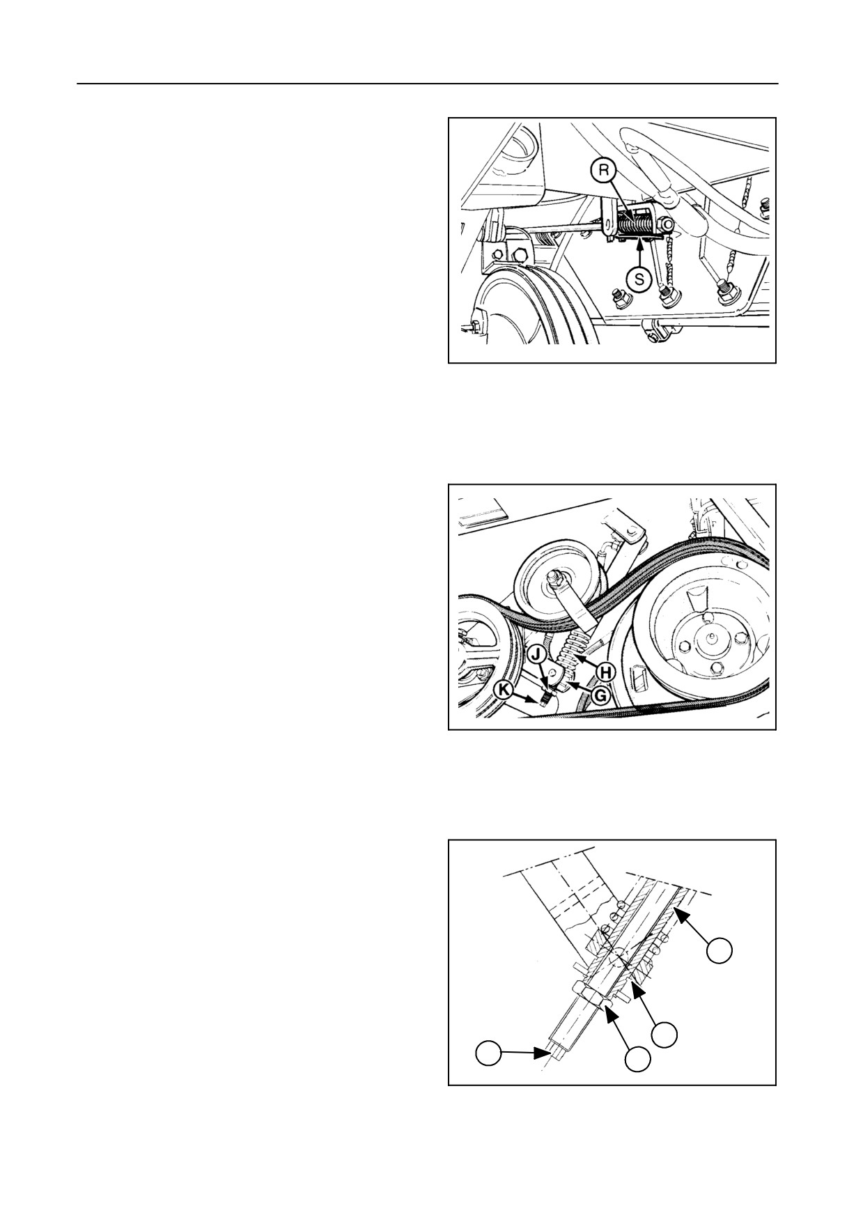
STRAW ELEVATOR AND HEADER ENGAG-
ING BELT
Models TX62-63 -- Figure 3
Models TX64PLUS-65PLUS-66-67-68-68PLUS --
Figure 4
Correct belt tension (in engaged position):
Spring length C = indicator plate length D.
Adjust with nuts E.
Adjust the belt guide F so that it is at a maximum
distance of 7 mm from the engaged belt, through-
55036
out the belt guide circumference.
3
TX62-63
Proceed as follows to check and adjust the ten-
sion of the straw elevator and header engaging
belt, of the threshing mechanism engaging belt
(item 4) and of the unloading system engaging
belt (item 3).
CAUTION:
For header, threshing and unloading
system:
Make sure nobody is near the combine
when disengaging the drive belt, even
when the engine is not running!
Make sure nobody is near the combine
when restarting the engineas somecom-
30214
ponents may rotate for a while.
4
TX64PLUS-65PLUS-66-67-68-68PLUS
5-2
SECTION 5
Proceed as follows per drive belt:
NOTE:
For models TX62-63, only steps 5 to 7 are ap-
plicable.
1. Start the engine.
2. Run the engine at maximum speed for a
short time.
3. Stop the engine.
4. Turn the key clockwise to the ignition posi-
55033
tion.
5
TX62-63
5. Only engage the drive belt to be checked
(one belt at a time!)
6. Check belt tension and adjust, if necessary.
7. Disengage the drive belt.
3
UNLOADING SYSTEM ENGAGING BELT
Proceed as described above.
Models TX62-63 -- Figure 5
30213
(underneath steering platform)
6
TX64PLUS-65PLUS-66-67-68-68PLUS
Correct belt tension (in engaged position):
Spring length R = indicator plate length S.
Models TX64PLUS-65PLUS-66-67-68-68PLUS --
Figures 6 and 7
Correct belt tension (in engaged position):
Notch of part H is visible just underneath block G.
Adjustment
1. Loosen lock nut J.
2. Adjust the spring tension by turning rod K so
N
that the notch in adjusting part H is just visible
K
J
underneath block G.
51910
3. Tighten lock nut J.
7
5-3
ADJUSTMENTS AND MAINTENANCE
4
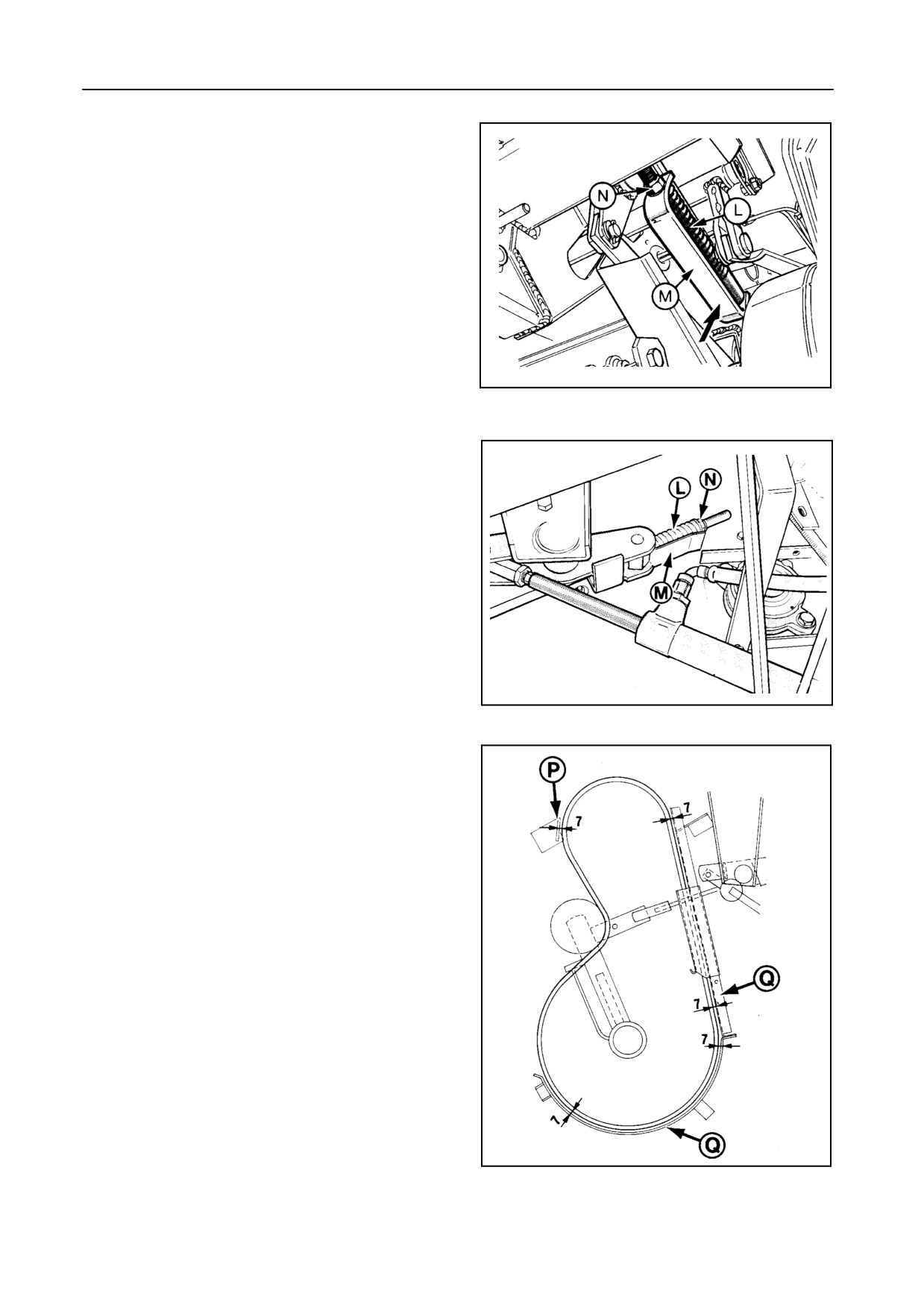
MAIN ENGAGING BELT
Proceed as described in paragraph 2.
Models TX62-63 -- Figure 8
(underneath steering platform)
Correct belt tension (in engaged position):
Spring length L corresponds with the notch in
plate M.
Adjust with nut N.
55037
8
TX62-63
Models TX64PLUS-65PLUS-66-67-68-68PLUS --
Figure 9
Correct belt tension (in engaged position):
Spring length L = indicator plate length M.
Adjust with nut N.
30216
9
TX64PLUS-65PLUS-66-67-68-68PLUS
All Models
Adjust the belt guides P and Q so that they are at
a maximum distance of 7 mm from the engaged
belt, throughout the belt guide circumference.
30224
10
5-4
SECTION 5
5
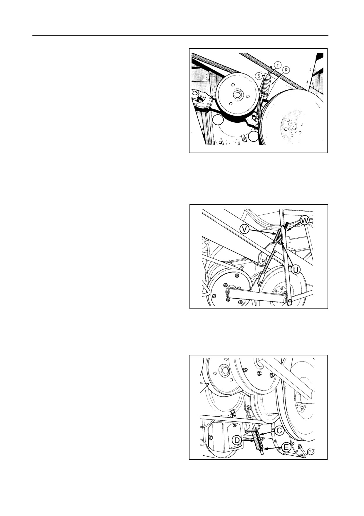
CLEANING SHOE DRIVE BELT
S Self-levelling cleaning shoe -- Figure 11
Correct belt tension:
Spring length R = indicator plate length S.
Adjust with nut T.
S Fixed cleaning shoe -- Figure 12
Correct belt tension:
A
Spring length U = indicator plate length V.
Adjust with nut W.
B
21072
11
6
ECCENTRIC SHAFT DRIVE
S Self-levelling cleaning shoe -- Figure 11
Drive shaft halves A and B can only be con-
nected together in one position of the splines.
S Fixed cleaning shoe -- Figure 13
Correct belt tension:
Spring length C = indicator plate length D.
Adjust with nut E.
42938
12
42933
13
5-5
ADJUSTMENTS AND MAINTENANCE
7
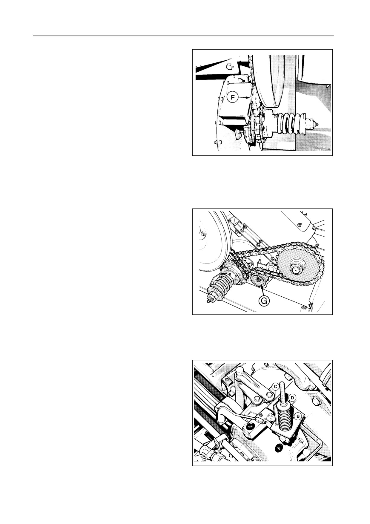
ROTO-THRESHER AND RETURNS CROSS
AUGER DRIVE CHAIN -- Figure 14
Tension the chain with idler sprocket F.
21073
14
8
RETURNS AUGER DRIVE CHAIN -- Figure 15
Tension the chain with idler G.
42795
15
9
MAIN DRIVE BELT -- Figure 16
Correct belt tension:
Spring length B = indicator plate length C.
Adjust with nut D.
20860
16
5-6
SECTION 5
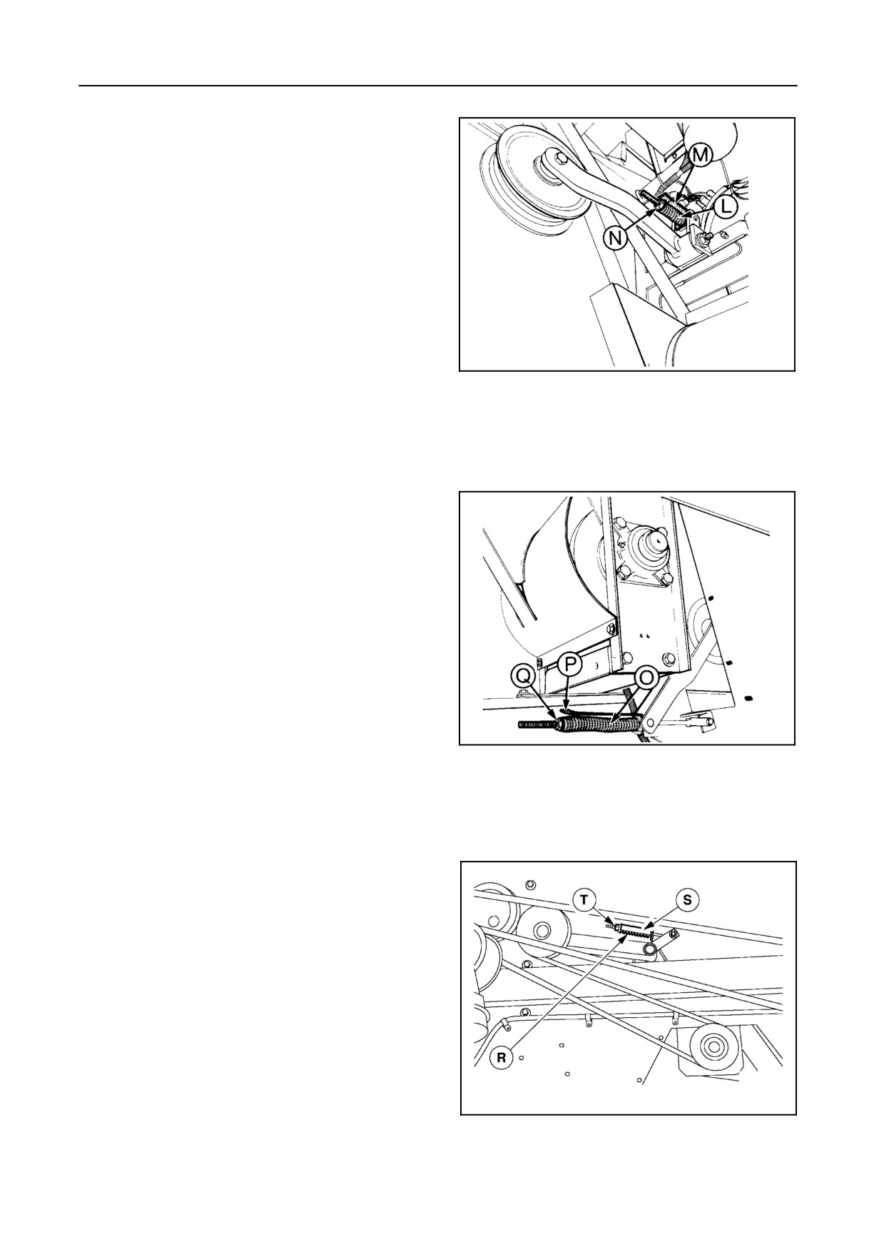
10 STRAW CHOPPER FRONT DRIVE BELT
[if fitted] -- Figure 17
Correct belt tension:
Spring length L = indicator plate length M.
Adjust with nut N.
42929
17
11
STRAW CHOPPER REAR DRIVE BELT
[if fitted] -- Figure 18
Correct belt tension:
Spring length O = indicator plate length P.
Adjust with nut Q.
42928
18
12
CHAFF SPREADER DRIVE BELT
[if fitted] -- Figure 19
Correct belt tension:
Spring lenght R = indicator length S.
Adjust with nut T.
43209
19
5-7
ADJUSTMENTS AND MAINTENANCE
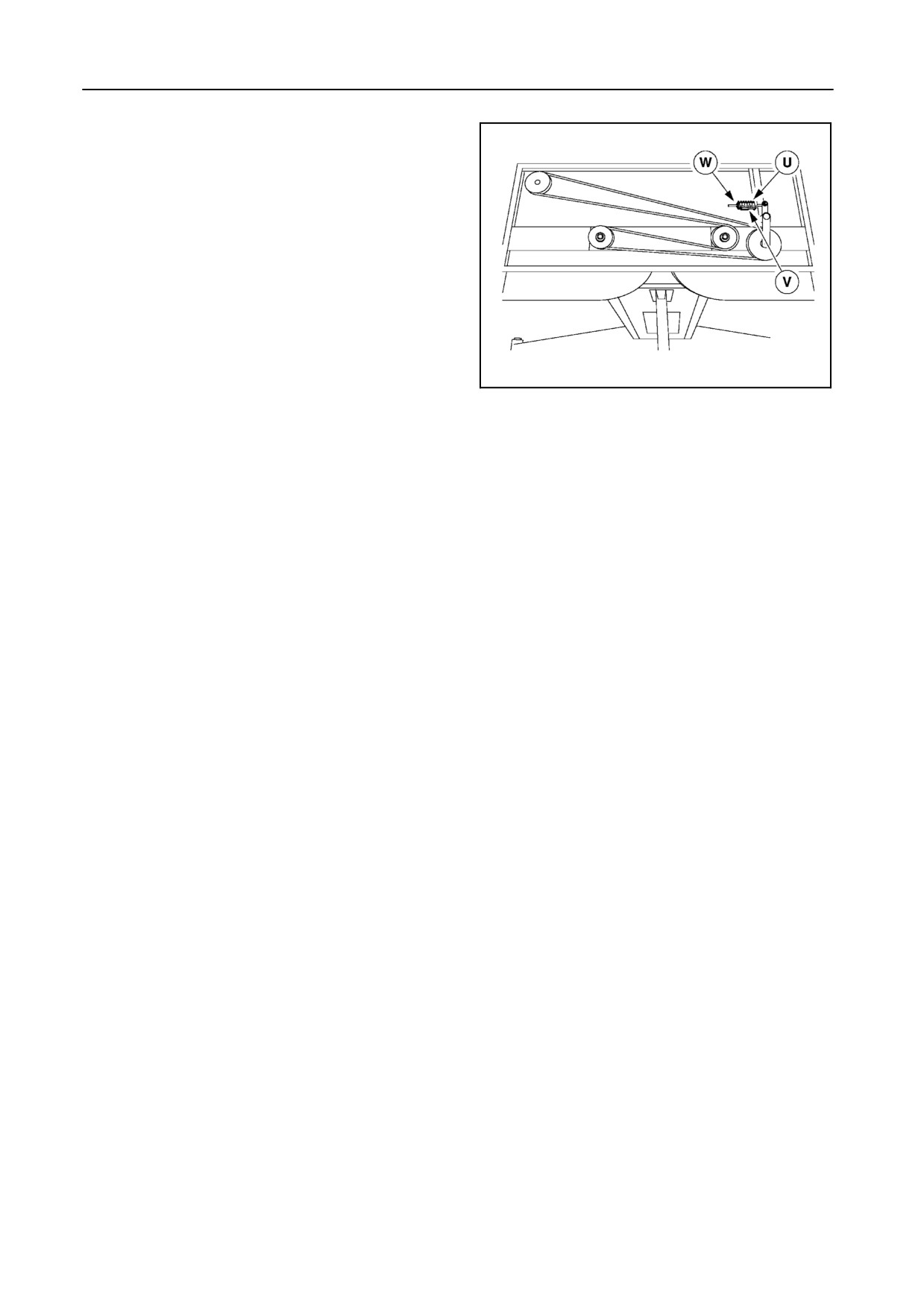
13
CHAFF SPREADER DISCS DRIVE BELT
[if fitted] -- Figure 20
Correct belt tension:
Spring length U = indicator length V.
Adjust with nut W.
43208
20
5-8
SECTION 5
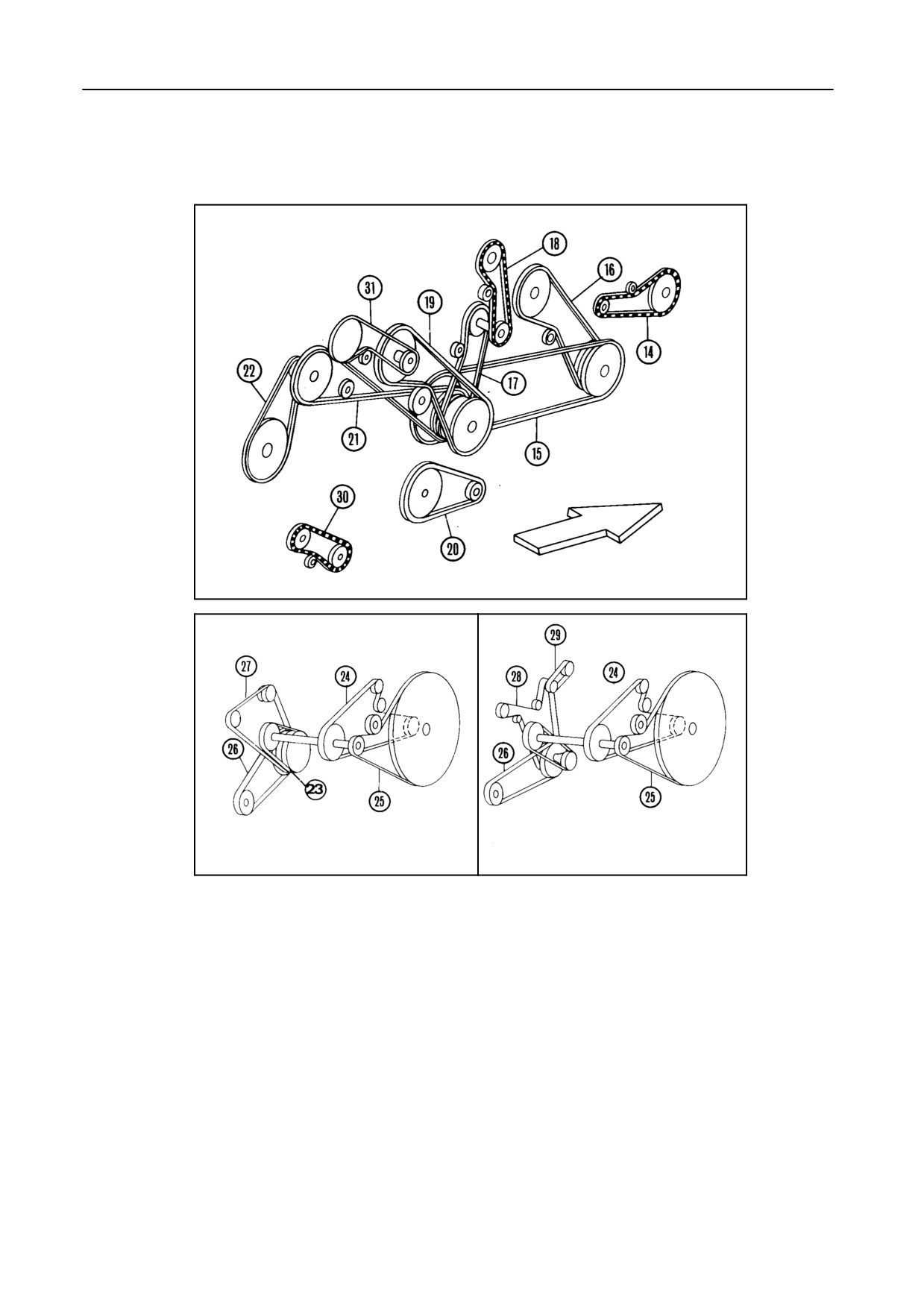
DRIVE BELTS AND CHAINS
[right-hand side] -- Figure 21
30218
TX68
TX62-63-64PLUS -65PLUS -66-67-68PLUS
30219
30220
21
14 Unloading system drive chain
24 Cooling fan drive belt
15 Drum vari-drive belt
25 Rotary dust screen drive belt
16 Beater drive belt
26 Hydraulic pump drive belt
17 Grain storage drive belt
27 Alternator and air conditioning compressor drive
18 Grain elevator drive chain
belt (Model TX68)
19 Rotary separator drive belt
28 Alternator drive belt
20 Cleaning fan vari-drive belt
29 Air conditioning compressor drive belt (Models
21 Straw walker intermediate shaft drive belt
TX62-63-64PLUS-65PLUS-66-67-68PLUS)
22 Straw walker drive belt
30 Returns auger drive chain
23 Cooling system intermediate shaft drive belt
31 Straw Flow beater drive belt
5-9
ADJUSTMENTS AND MAINTENANCE
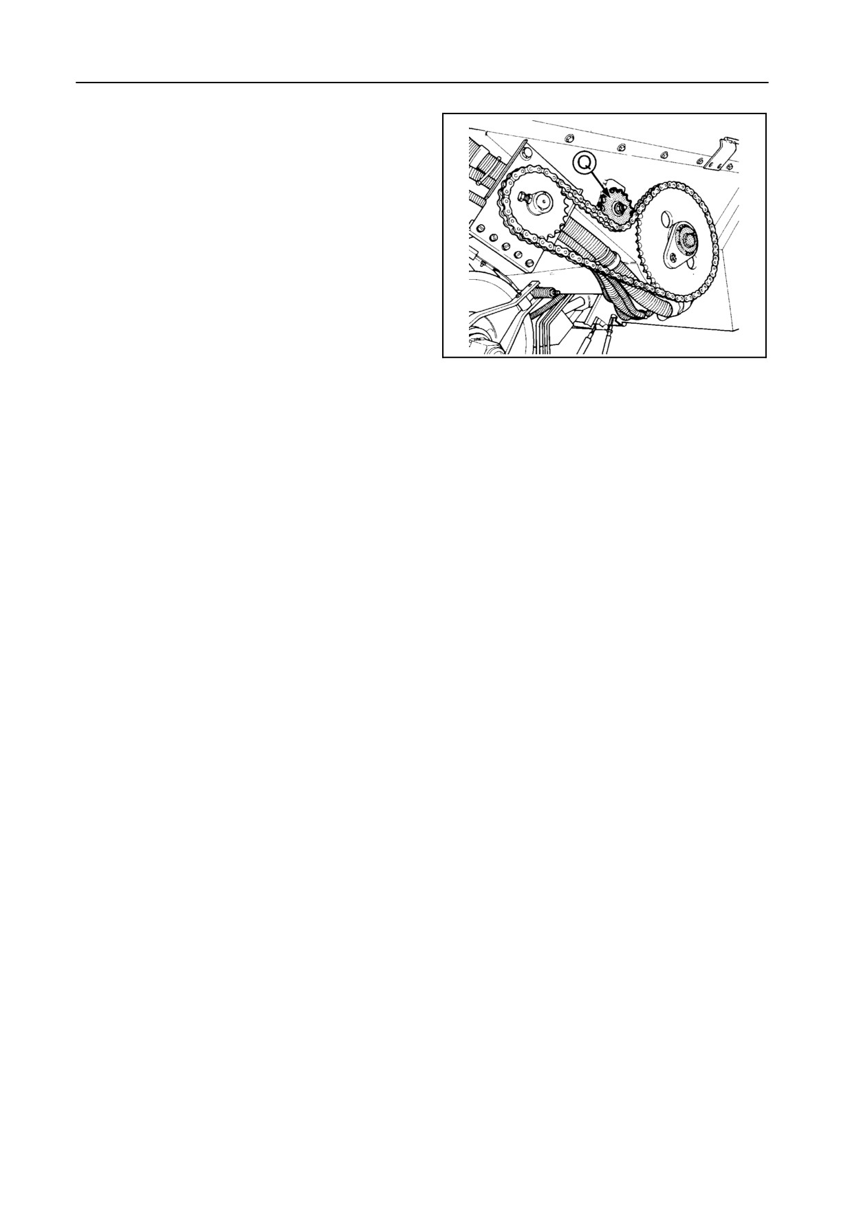
14 UNLOADING SYSTEM DRIVE CHAIN --
Figure 22
Tension the chain with sprocket Q.
42807
22
15 DRUM VARI-DRIVE BELT
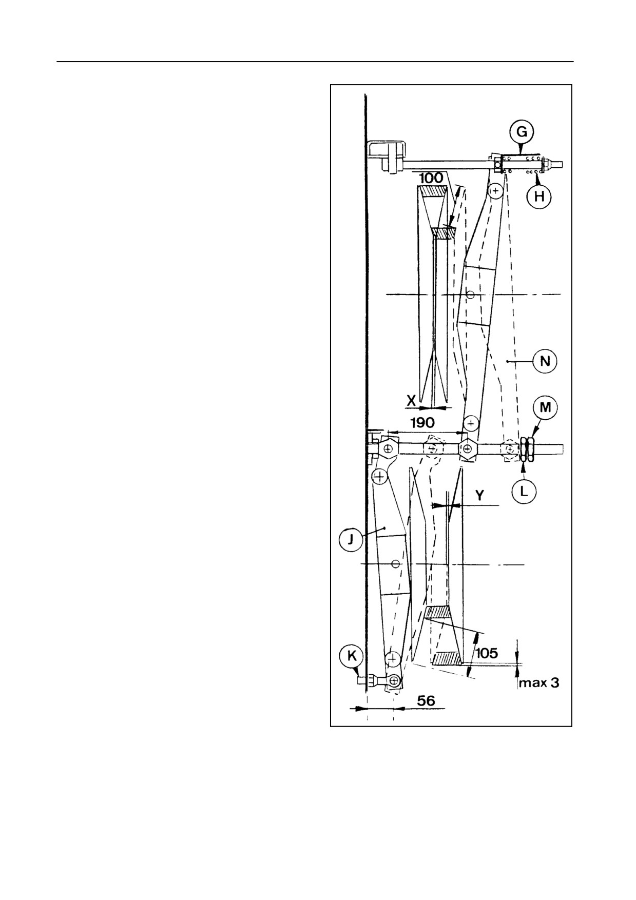
a) Standard drum variator drive [if installed]
Figure 23
The tension of the drum vari-drive belt is cor-
rect when spring H is adjusted to the length
of the indicator plate G.
Checking variator adjustment
Start the engine and engage the threshing
mechanism. Move the drum variator to MINI-
MUM. Stop the engine.
Distance X should be minimum 1 mm (clear-
ance measured between driven sheaves).
Move the variator to MAXIMUM.
Distance Y should be minimum 1 mm (clear-
ance measured between drive sheaves).
5-10
SECTION 5
Adjustment
a) Variator on MINIMUM position:
The variator arms J should be against the
frame.
The factory setting of the (new) belt depth on
the drive sheaves is 105 mm and an initial
setting of eyebolt K is 56 mm.
If needed, i.e. if measurement X is less than
1 mm, adjustment can be carried out with the
lock nut on eyebolt K (moving the variator
arm J to the outside).
Inthecaseof astretchedbelt, thebelt canbe
allowed to extend 3 mm beyond the edge of
the driven sheaves.
b) Variator on MAXIMUM position:
The factory setting of the (new) belt depth on
the driven sheaves is 100 mm.
If necessary, i.e. if measurement Y is less
than 1 mm, adjust with nuts L and M (moving
the variator arm N to the inside).
In the case of a stretched belt, the belt may
be allowed to extend 3 mm beyond the edge
of the drive sheaves.
51588
23
5-11
ADJUSTMENTS AND MAINTENANCE
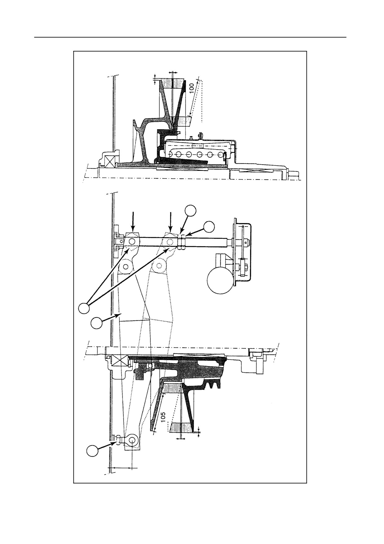
b)
Torque-sensing drum variator
[if
Adjustment
installed] -- Figure
24
The drum variator belt is tensioned automati-
(i)
Variator on MINIMUM position:
cally according to the torque on the drum
shaft (“Torque-sensing drum variator”).
Move pivot block D against the frame.
Adjust nut K until a belt depth of 105 mm
on the intermediate shaft pulleys is ob-
tained or distance X measures minimum
1 mm. The initial setting of nut K is 56
Checking variator adjustment
mm.
Start the engine and engage the threshing
mechanism. Move the drum variator to
(ii)
Variator on MAXIMUM position:
MINIMUM. The variator arms J should be
against the frame. Stop the engine.
Move pivot block D towards nuts L and M
Distance X, which is the clearance between
until a belt depth of 100 mm on the drum
the driven sheaves, should measure mini-
shaft pulleys is obtained or distance Y
mum 1 mm.
measures minimum 1 mm.
Move the drum variator to MAXIMUM.
Tighten nut L and jam nut M against pivot
Distance Y, which is the clearance between
block D.
the drive sheaves, should measure mini-
mum 1 mm.
NOTE:
NOTE:
In both minimum and maximum posi-
In both minimum and maximum position
tion the variator belt should not pro-
the variator belt should not protrude more
trude more than 3 mm beyond the va-
than 3 mm beyond the variator sheaves.
riator sheaves.
5-12
SECTION 5
X
max 3
minimum maximum L
M
D
J
max 3
Y
K
56
52068
24
5-13
ADJUSTMENTS AND MAINTENANCE
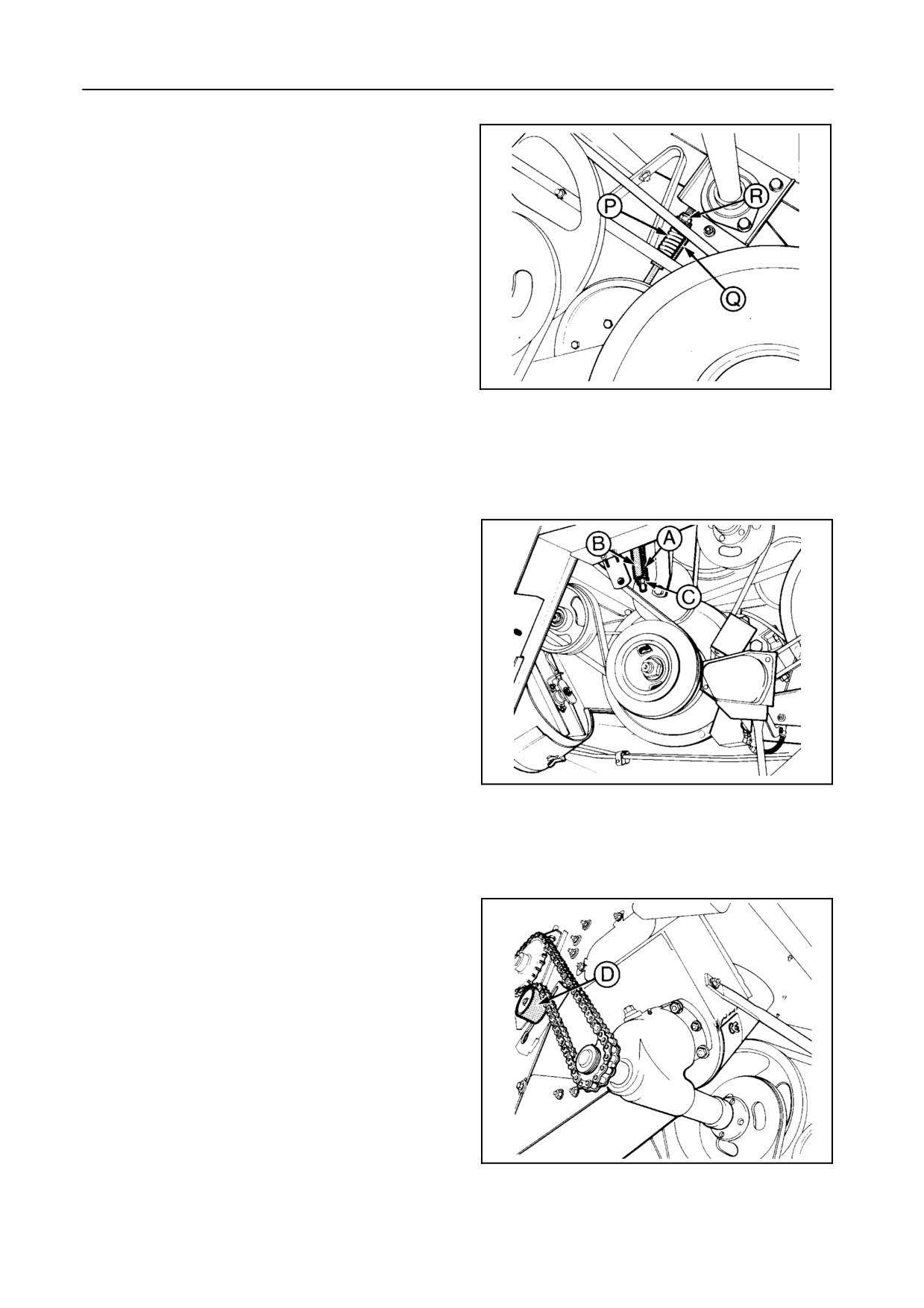
16 BEATER DRIVE BELT -- Figure 25
Correct belt tension:
Spring length P = indicator plate length Q.
Adjust with nut R.
42921
25
17 GRAIN STORAGE BELT -- Figure 26
Correct belt tension:
Spring length A = indicator plate length B.
Adjust with nut C.
42951
26
18 GRAIN ELEVATOR DRIVE CHAIN -- Figure 27
Tension the chain with nylon idler D.
42930
27
5-14
SECTION 5
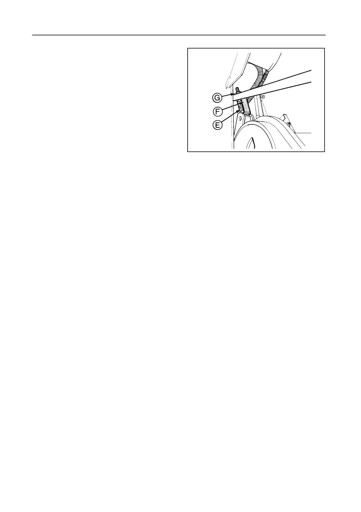
19 ROTARY SEPARATOR DRIVE BELT --
Figure 28
Correct belt tension:
Spring length E = indicator plate length F.
Adjust with nut G.
42917
28
5-15
ADJUSTMENTS AND MAINTENANCE
20
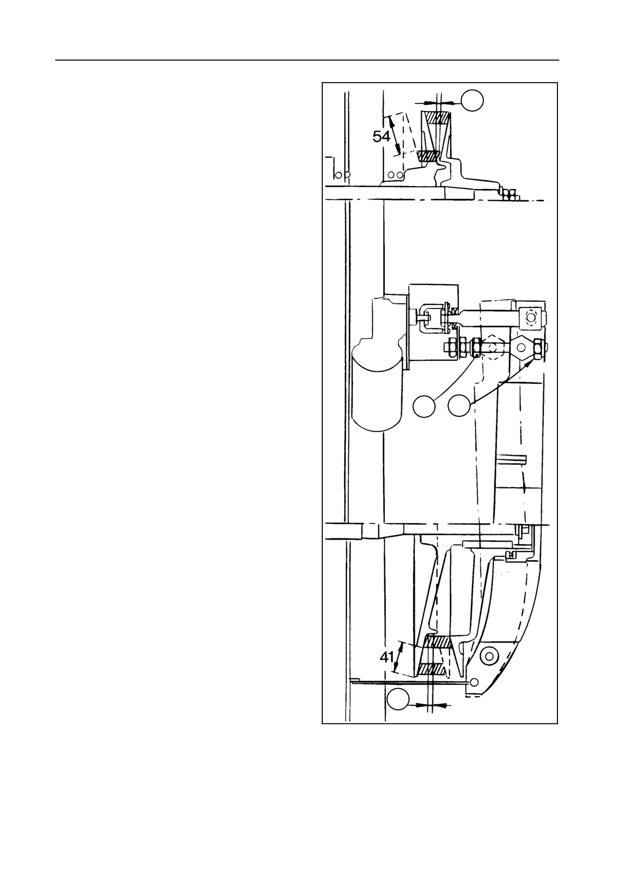
CLEANING FAN VARI-DRIVE BELT --
Figure 29
X
Checking
Start the engine and engage the threshing
mechanism.
Move the fan variator to MINIMUM.
Stop the engine and check clearance X between
the sheaves on the fan shaft.
Clearance X should be minimum 1 mm.
Move the fan variator to MAXIMUM.
Clearance Y should be minimum 1 mm.
Adjustment
Adjust with nut S or T.
The factory setting is:
S Maximum 54 mm belt depth on the driven
sheaves.
S Minimum 41 mm belt depth on the drive
sheaves.
In the case of a stretched belt, the belt loop
T
S
around the sheaves may be allowed to extend
maximum 3 mm beyond the edge of the sheaves.
Y
51523
29
5-16
SECTION 5
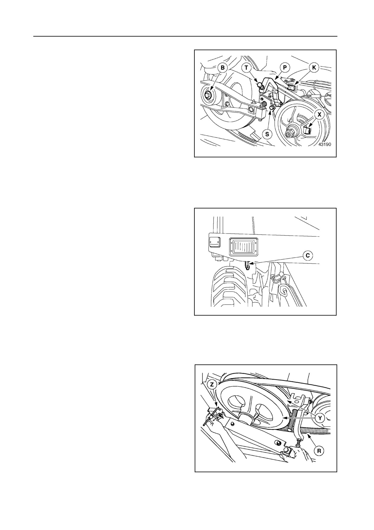
Low speed fan variator [if installed] --
Figures 30 to 32
To change the variator sheaves and belt, proceed as
follows:
1. Start the engine and engage the threshing mech-
anism.
2. Set the fan variator on maximum speed.
3. Stop the engine.
43190
30
4. Install a restictor X so that the fan sheave, which
is spring-loaded, cannot move back.
5. Plug in connector C at the front railing and switch
on the parking lights.
6. Press switch K to open the variator and hold up
pawl P until the variator arms are free.
7. Remove pin Z and bolt B.
8. Remove the two sheaves Y and belt R.
9. Install the other sheaves and the belt.
10. Tighten bolt B to 50 Nm.
43191
31
11. Reinstall the variator arms and secure them in
place with pin Z.
12. Press switch K to close the variator while turning
the pulley by hand until it is possible to remove
restrictor X.
13. Plug out connector C.
14. Adjust bolts T and S as explained above under
subheadings ‘‘Checking’’ and Adjustment’’.
43192
32
5-17
ADJUSTMENTS AND MAINTENANCE
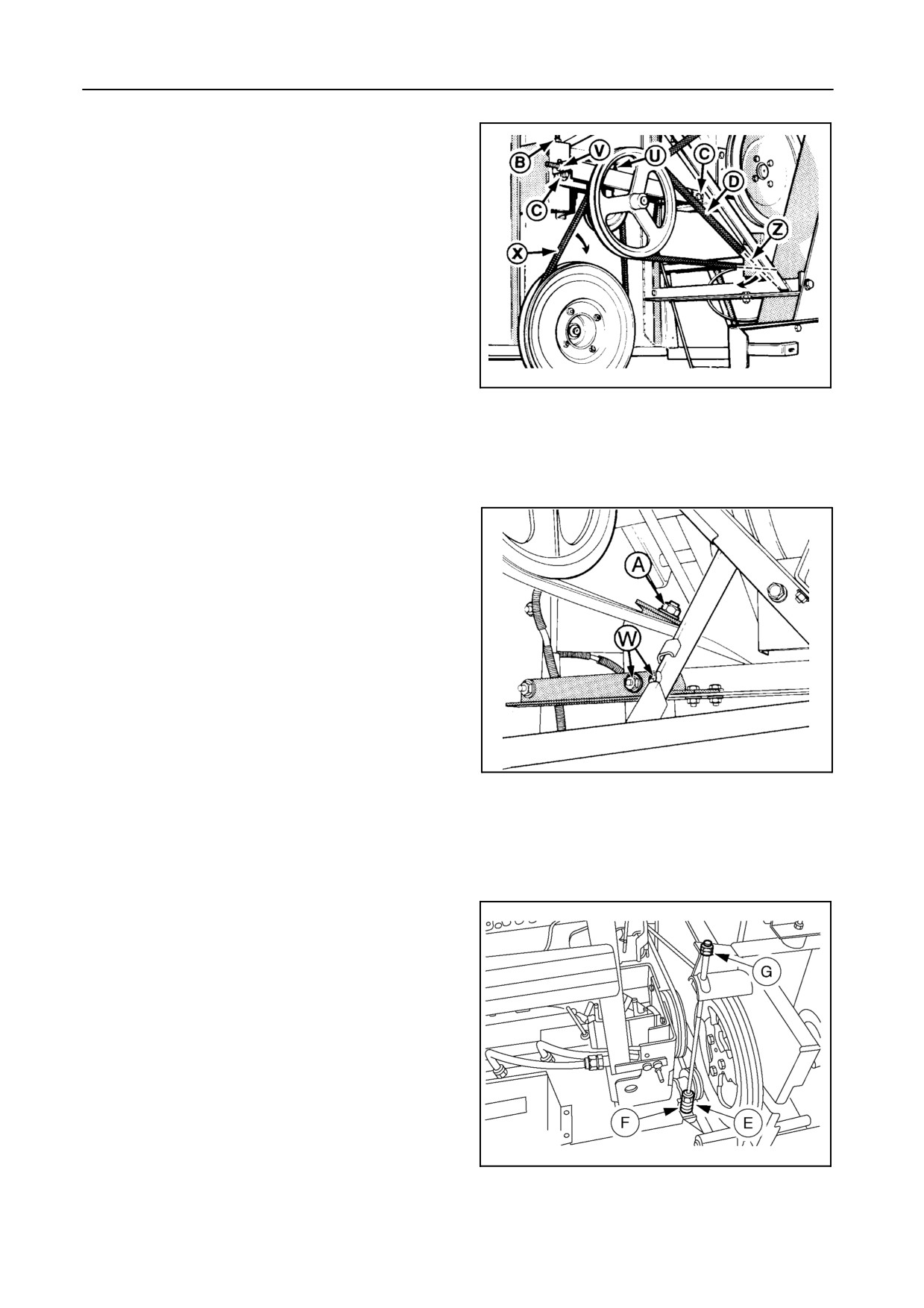
21 STRAW WALKER INTERMEDIATE SHAFT
DRIVE BELT -- Figures 33 and 34
The belt tension is correct when belt D can be de-
flected 14 mm at Z when applying a force of 17 N.
Adjust with rod V after loosening the three bolts
U. Loosen bolts W and adjust pulley A and its
support slightly downwards [forming an angle of
approximately 35° with the straight line between
the two pulleys -- front pulley upper side and rear
pulley lower side (view from the rear)], so that a
21082
clearance of 2 to 3 mm exists between both belt
halves. Retighten bolts W.
33
22 STRAW WALKER DRIVE BELT -- Figure 33
The belt tension is correct when the belt can be
deflected 5 mm when applying a force of 41 N
halfway between the pulleys at X .
Adjust with rod B after loosening bolts C.
Retighten bolts C.
NOTE:
Adjustments of the straw walker drive belt and
the straw walker intermediate shaft drive belt
42920
should be carried out together.
34
23 COOLING SYSTEM INTERMEDIATE SHAFT
DRIVE BELT -- Figure 35
Correct belt tension:
Spring length E = indicator plate length F.
Adjust with nut G.
54738
35
5-18
SECTION 5
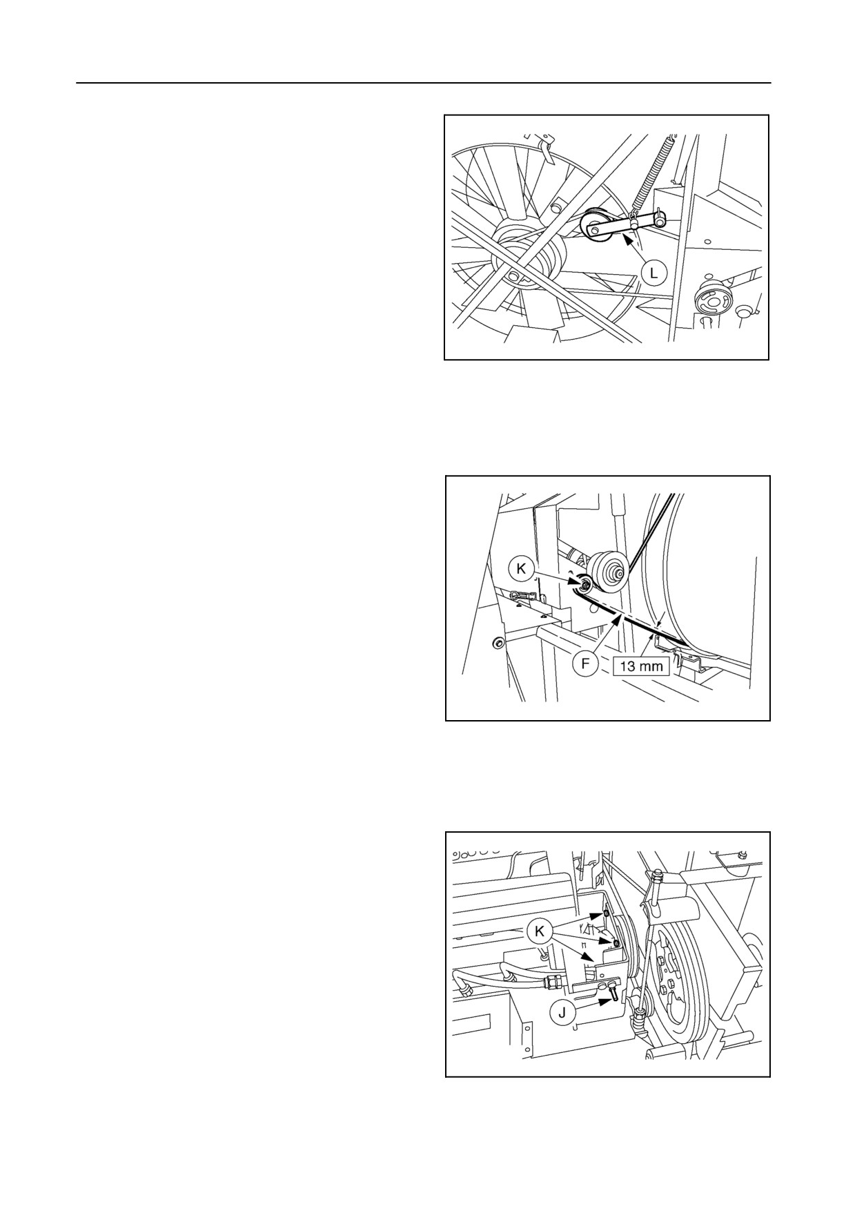
24 COOLING FAN DRIVE BELT -- Figure 36
Spring-loaded idler L.
No adjustment needed.
54739
36
25 ROTARY DUST SCREEN DRIVE BELT --
Figure 37
Applying a force F = 1.8 to 3.5 N at the midpoint of
the belt should deflect the belt 13 mm.
Loosen nut K to adjust.
54740
26 HYDRAULIC PUMP DRIVE BELT -- Figure 38
37
Correct belt tension:
Models TX62-63-64PLUS-65PLUS-66-67
Applying a force of 3 daN at the midpoint of the
belt should deflect the belt 7.6 mm.
Loosen three nuts K and adjust with threaded rod
J.
Models TX68-68PLUS
Applying a force of 2.7 daN at the midpoint of the
belt should deflect the belt 6.7 mm.
54741
Loosen three nuts K and adjust with threaded rod
38
J.
5-19
ADJUSTMENTS AND MAINTENANCE
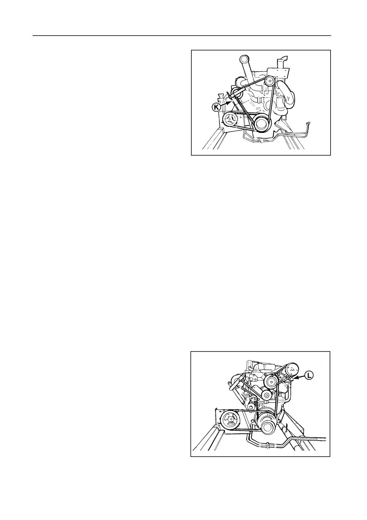
27 ALTERNATOR AND AIR CONDITIONING
COMPRESSOR DRIVE BELT
[Models TX68-68PLUS] -- Figure 39
Correct belt tension:
Applying a force of 3 daN halfway the belt be-
tween the engine pulley and the alternator will
deflect the belt 7 mm.
Adjust by moving the alternator held by two nuts
on the threaded rod K.
30223
39
TX68-68PLUS
28 ALTERNATOR DRIVE BELT
[Models TX62-63-64PLUS-65PLUS-66-67]
Self-adjusting idler, no adjustment needed.
29 AIR CONDITIONING COMPRESSOR DRIVE
BELT [Models TX62-63-64PLUS-65PLUS-66-67] --
Figure 40
Correct belt tension:
Applying a force of 2.3 daN at the midpoint of the
belt between the two pulleys should deflect the
belt 3 mm.
Adjust by moving the compressor in the slotted
holes L.
30222
40
TX62-63-64PLUS-65PLUS-66-67
5-20