New Holland TX62, TX63, TX64 Plus, TX65 Plus, TX66, TX67, TX68, TX68 Plus. Operator's Manual - page 7
SECTION 5
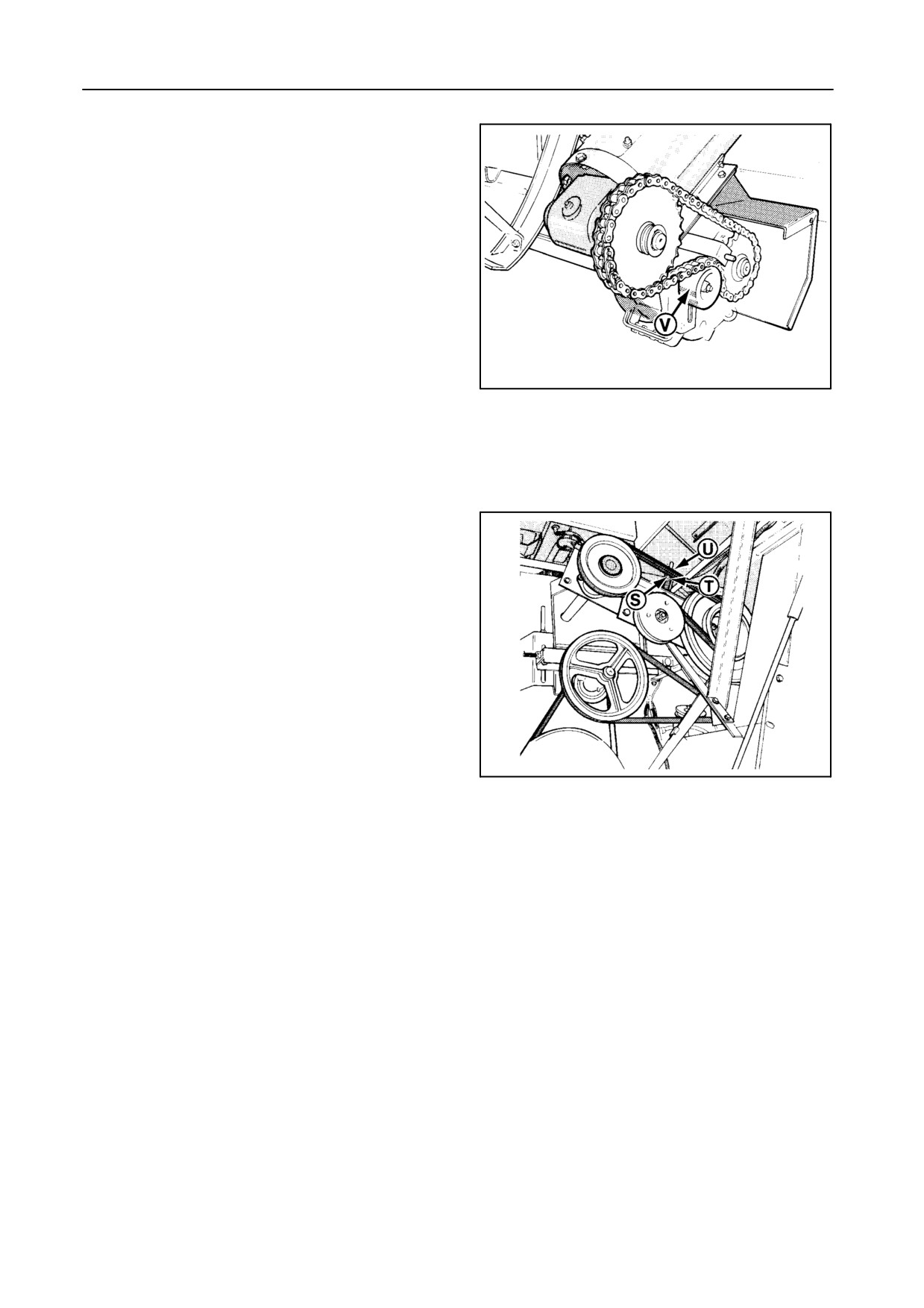
30 RETURNS AUGER DRIVE CHAIN
[right-hand side] [Models TX66-67-68-68PLUS]
Figure 41
Tension the chain with idler V.
30212
41
TX66-67-68-68PLUS
31 STRAW FLOW BEATER DRIVE BELT --
Figure 42
Correct belt tension:
Spring length S = indicator plate length T.
Adjust with nut U.
30217
42
5-21
ADJUSTMENTS AND MAINTENANCE
STRAW ELEVATOR
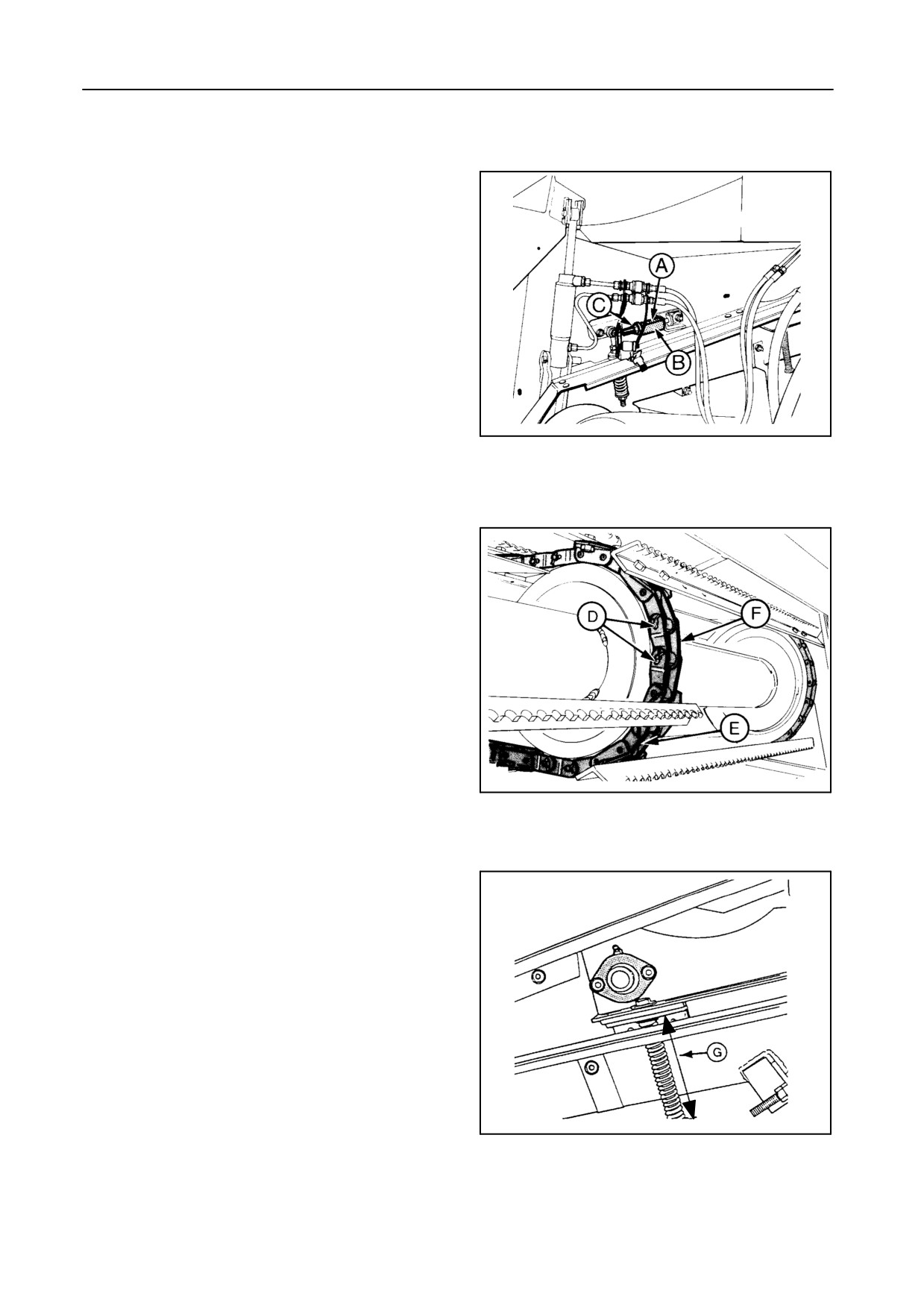
CHAIN TENSION -- Figures 43 and 44
The tension of the straw elevator chain is kept con-
stant by spring A which pushes the mounting sup-
ports of the lower shaft forwards.
Correct chain tension:
Spring length A = indicator plate length B (both
sides).
42950
Adjust with nut C.
43
As the chain stretches, the supports will gradually
move towards the end of the slots.
Inthiscase, remove half a linkof thethree chainsand
readjust the chain tension.
Proceed as follows:
1. Loosen nuts C on both sides to slacken the straw
elevator chains.
2. Move the straw elevator lower shaft to the rear.
3. Remove cotter pins D and open chains E.
4. Remove half a link F.
5. Reassemble chains E with cotter pins D as
shown.
55012
6. Readjust the chain tension.
44
Spring length A = indicator plate length B (both
sides).
For correct functioning of the middle shaft, distance
G between the two washers should be 175 ¦1 mm.
42776
45
5-22
SECTION 5
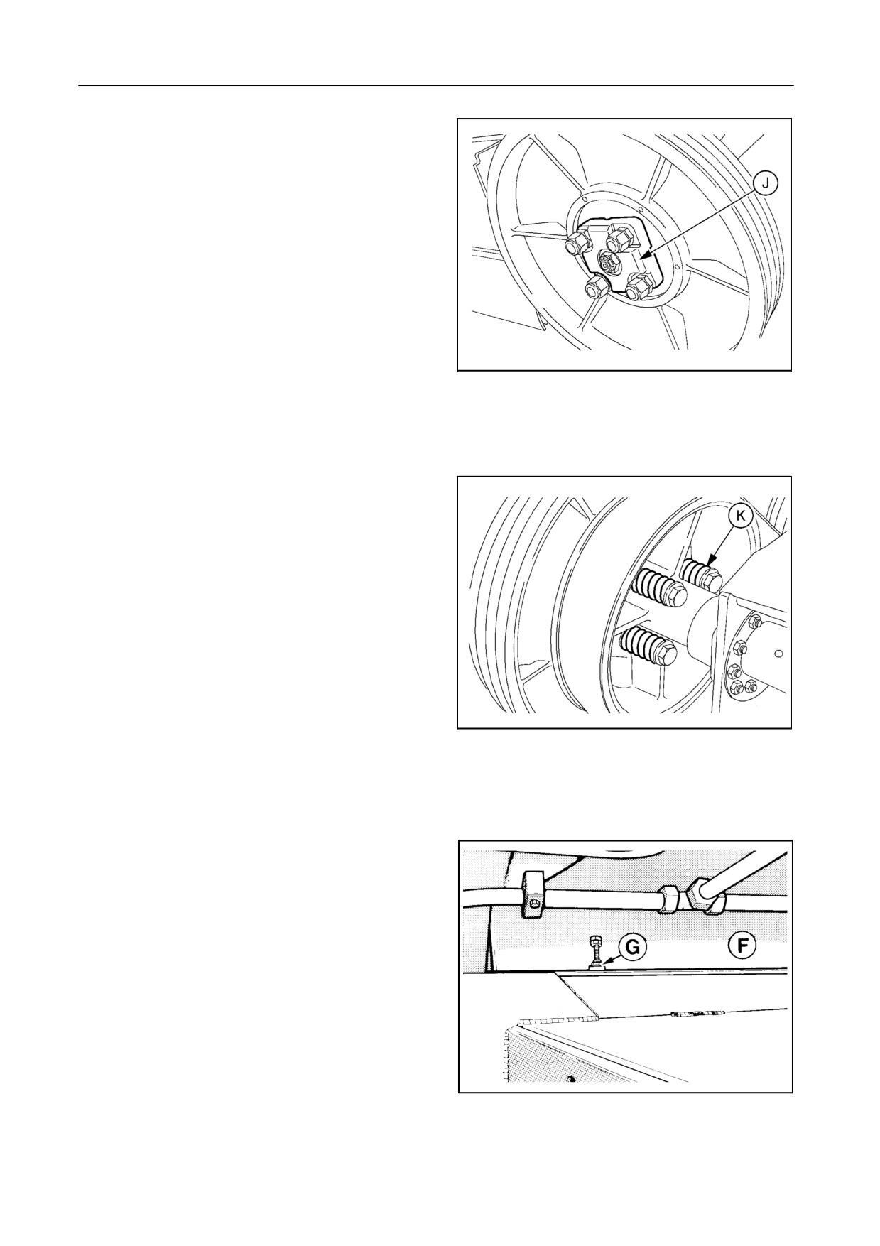
SLIP CLUTCH -- Figures 46 and 47
The audible slip clutch J is factory-set for average
conditions and must not be further tensioned.
Correct clutch tension ( in case of disassembly):
The length of spring K should measure 75.5 mm (slip
clutch torque is 600 Nm).
55784
46
55785
47
ANTIDUST PLATE -- Figure 48
An antidust plate is fixed to the cover F in front of the
drum. The lower part of the plate is adjustable. Adjust
nuts G until there is a clearance of 3 mm between the
plate and the drum rasp bars.
Remove the antidust plate when operating in maize.
21092
48
5-23
ADJUSTMENTS AND MAINTENANCE
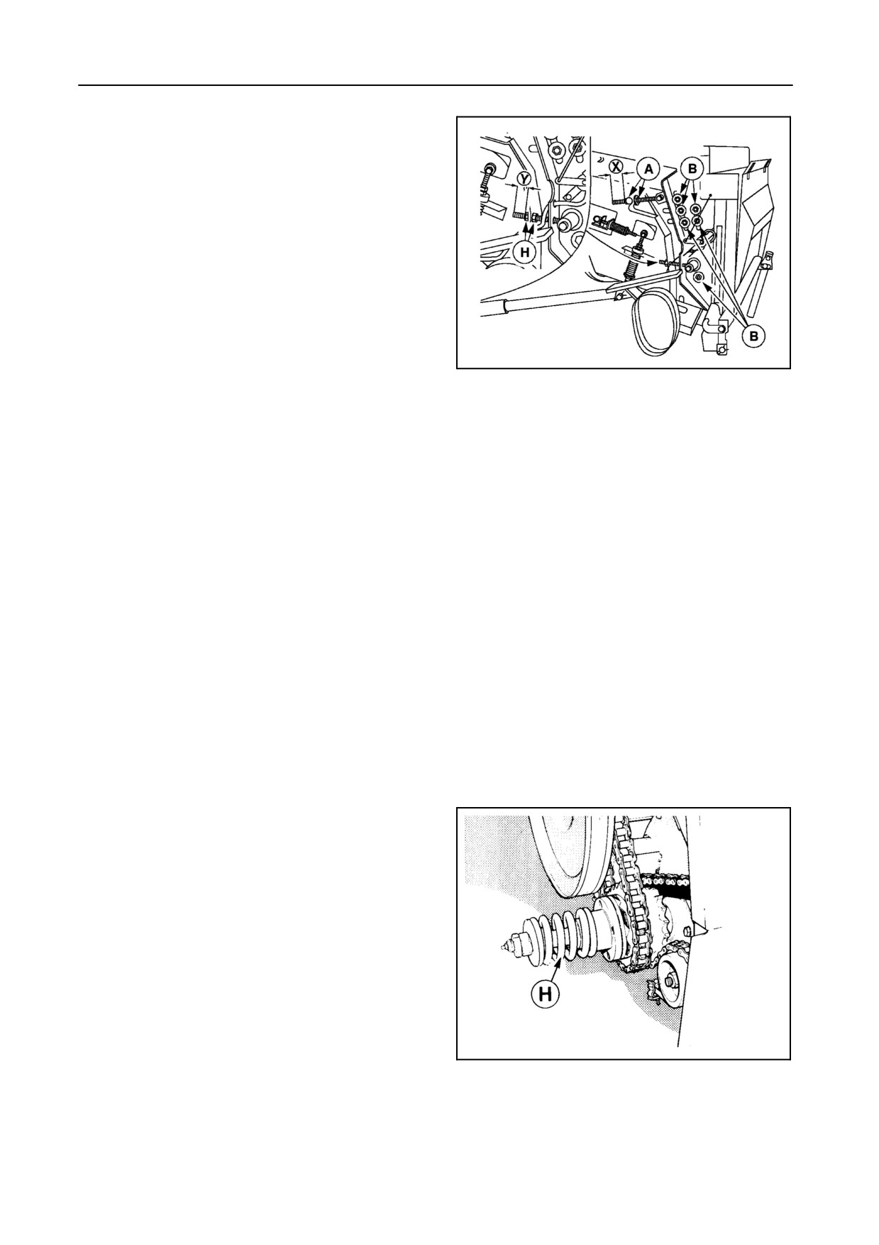
FRONT FACE ADJUSTMENT [if installed] --
Figure 49
The operating angle of the header is adjustable to im-
prove crop feeding. The angle of the straw elevator
front face can equally be adjusted by changing dis-
tance X (factory-set to 72 mm) and distance Y (facto-
ry-set to 49 mm).
To adjust the angle of the front face, proceed as fol-
lows on both sides of the machine:
1. Loosen six nuts B.
43182
49
2. Adjust distances X and Y between the header and
the straw elevator with nuts H.
3. Adjust the front face angle with nuts A.
4. Tighten nuts A and H.
5. Tighten nuts B to 240 Nm.
ATTENTION:
Make sure the straw elevator slats do not inter-
fere with the dust plates at the front part of the
straw elevator.
ROTO--THRESHERS
SLIP CLUTCH -- Figure 50
The slip clutch on the roto-thresher shaft protects the
returns drive line.
When correctly adjusted, the spring length H should
measure 86 mm.
21074
50
5-24
SECTION
5
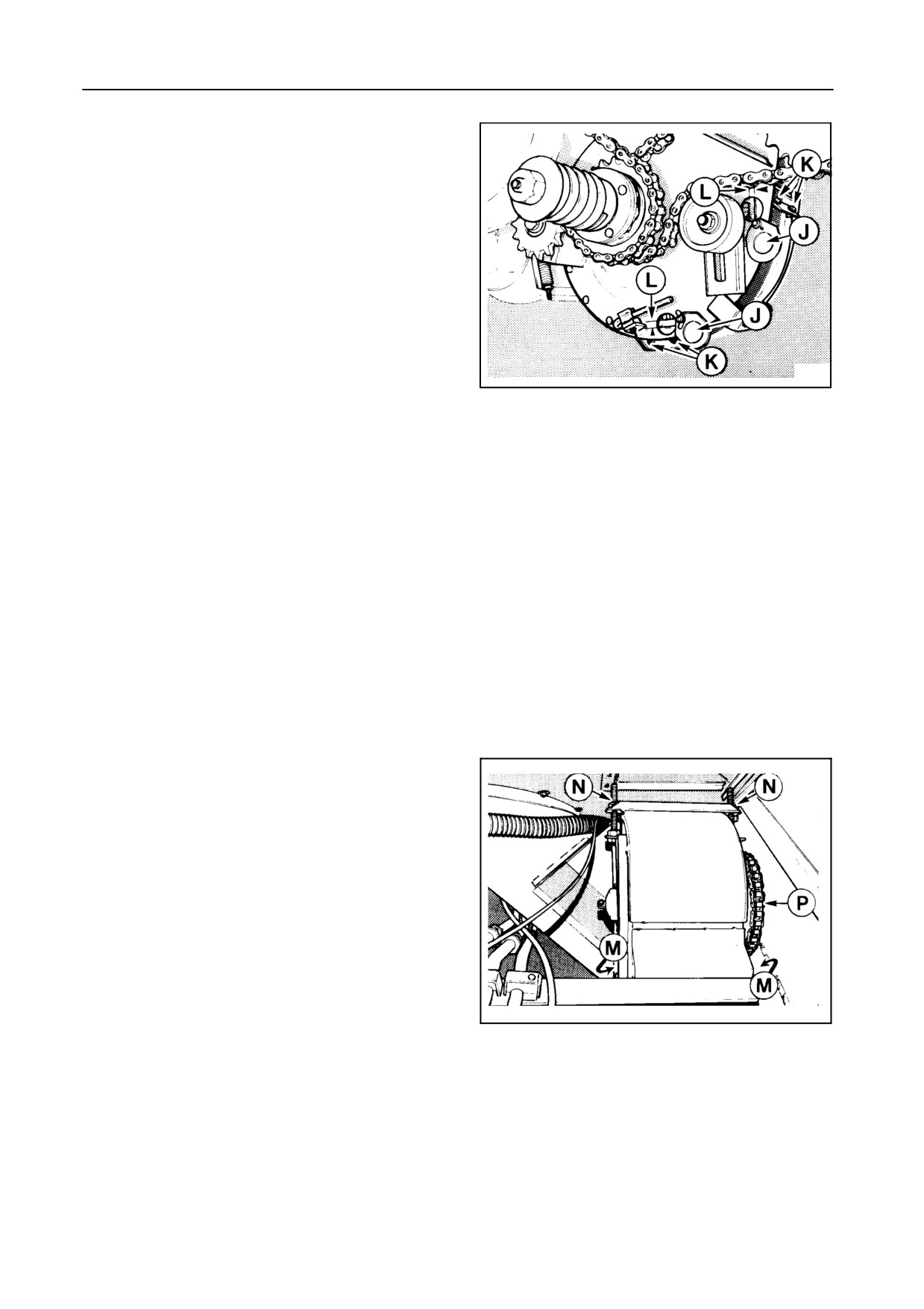
CONCAVE ADJUSTMENT -- Figure 51
Proceed as follows:
1. Open the covers above inspection holes J.
2. Loosen the four bolts K.
3. Move the roto-thresher concave to a minimum of
5 mm from the roto-thresher teeth (see L).
4. Check the adjustments through inspection holes
J. If grain crackage is experienced, increase dis-
21160
tance L.
51
5. Retighten the four bolts K.
6. Close the covers over the inspection holes J.
7. Models TX66-67-68-68PLUS only:
Proceed in the same way on the opposite side.
GRAIN ELEVATOR
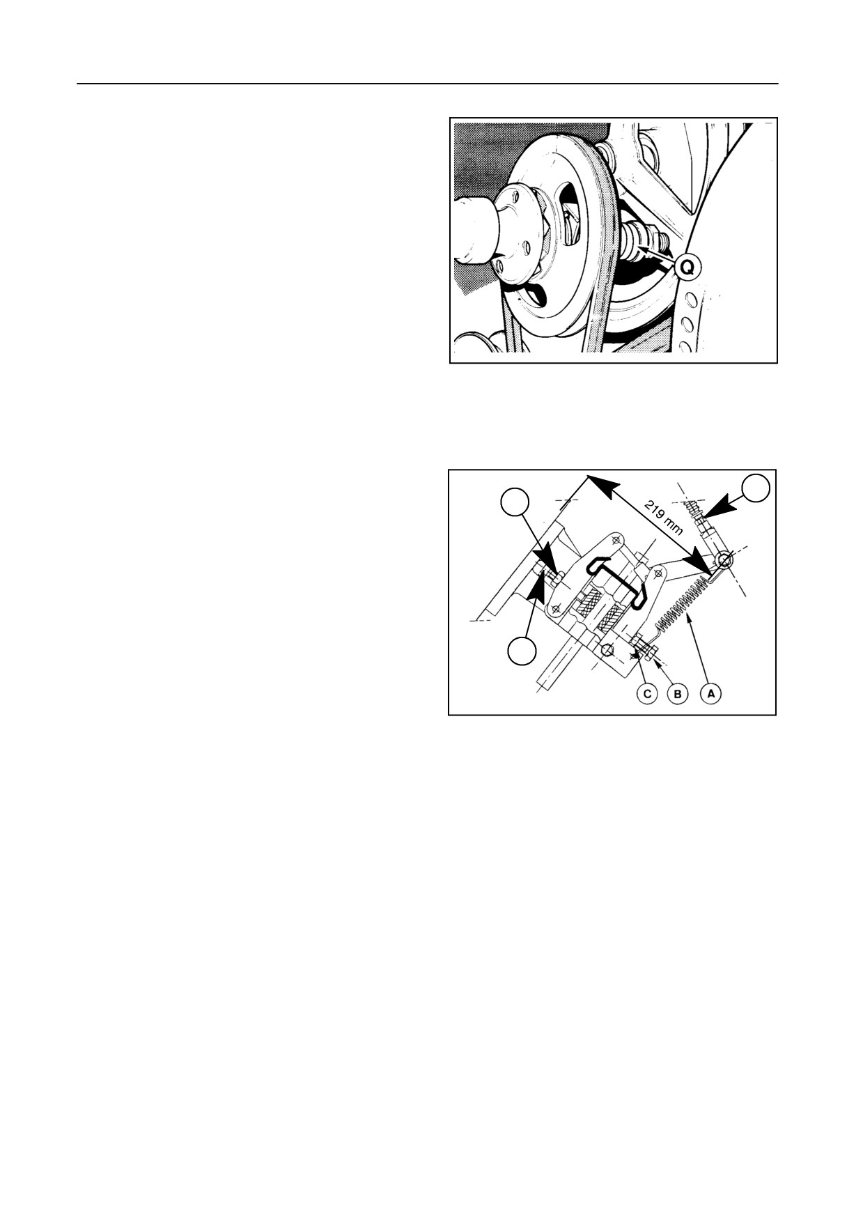
CHAIN TENSION -- Figure 52
The tension of the grain elevator chain can be ad-
justed at the top of the elevator, accessible through
the grain tank, after drive chain P has been slack-
ened.
Loosen bolts M and adjust with nuts N on both sides
of the elevator head.
ATTENTION:
To prevent bearing damage, ensure nuts N are
tightened evenly.
The tension of the grain elevator chain is correct
21093
when it is just possible to move a link laterally across
the lower sprocket by hand.
52
5-25
ADJUSTMENTS AND MAINTENANCE
SLIP CLUTCH -- Figure 53
To protect the clean grain drive line an audible slip
clutch is fitted to the gearbox. The slip clutch is fac-
tory-set for average crop conditions.
To adjust, compress spring Q completely and then re-
lease the nut 5
1/4 turns.
--
21094
53
BRAKES
PARKING BRAKE ADJUSTMENT
D
C
All models, except TX67 -- Figure 54
1. Disengage the handbrake in the cab. Do not re-
move spring A.
2. Loosen nuts C and bolts B.
B
3. Adjust dimension 219 mm with nuts D.
4. Turn bolts B by hand until they touch the brake
52041
blocks.
54
5. Loosen bolts B 1/6 of a turn and tighten screws C.
Model TX67 -- Figures 55 to 57
Every 500 operating hours or once a year a clearance
check and possible adjustment of the parking brake
has to be carried out.
Proceed as follows:
1. Park the combine on level ground and block the
wheels adequately (e.g. by means of wooden
blocks).
2. Measure the piston travel of the parking brake in
the following manner:
a) Remove rubber cap G.
b) Measure distance X.
5-26
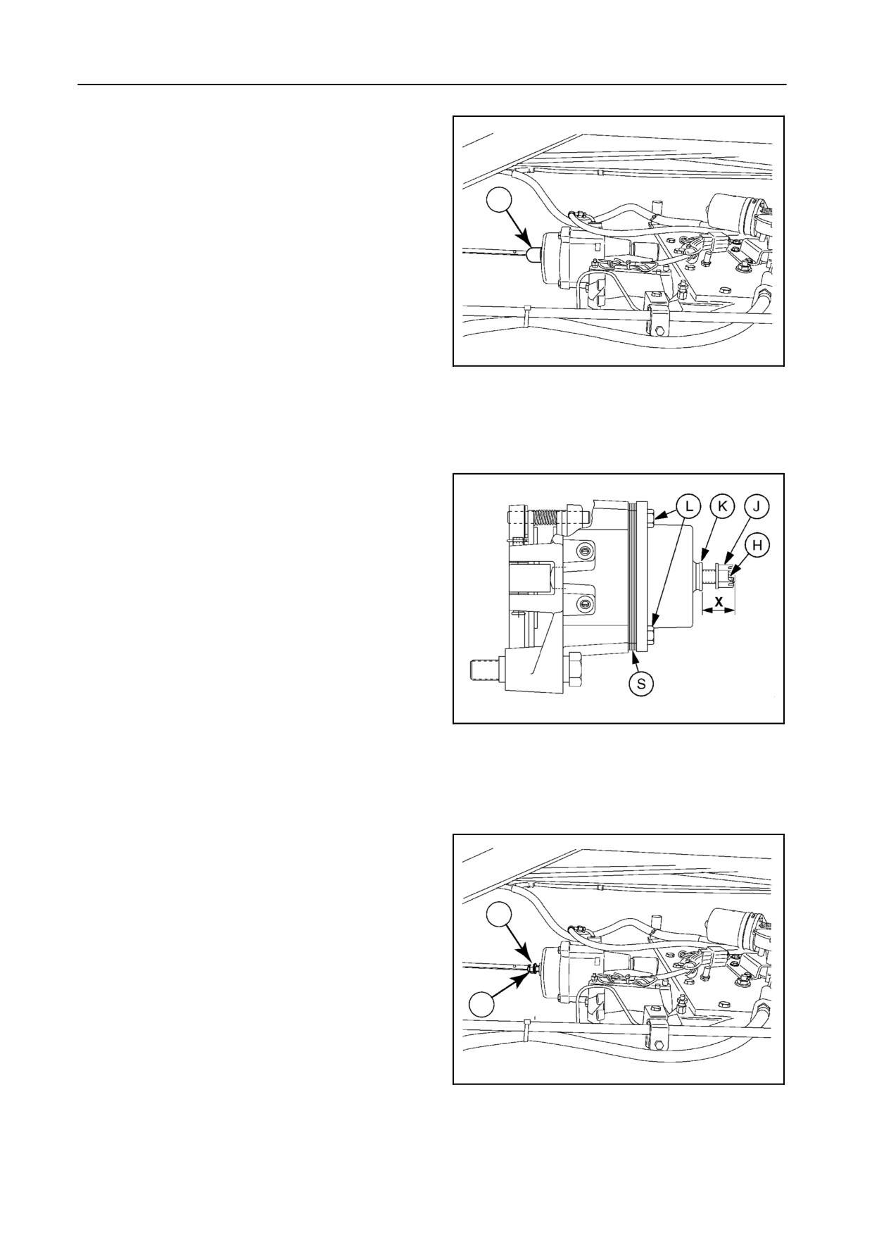
SECTION 5
c) Remove cotter pin H, screw nut J against the
end cap K and tighten to complete release of
the parking brake disc. Measure distance X
again. The difference between the two values
is the piston travel. Piston travel should be be-
G
tween 1.5 and 3.5 mm.
3.
If the piston travel exceeds 3.5 mm, one or more
shim layers S have to be removed. Removing one
layer of shims will reduce the piston travel by 2
mm. Each layer of shims consists of 3 sectional
parts (3x120°).
30840
To remove the shims, proceed as follows:
55
a) Loosen the three screws L. Turn out one screw
and remove the corresponding shim sec-
tion(s)
(one layer per 2 mm travel reduction).
Reinstall the screw. Proceed in the same way
for the two other sections.
ATTENTION:
Install the removed shim between the end cap
and the bolt head. This will prevent the shims
from getting lost. The removed shims will be
needed again when installing new brake pads
later on.
b) Retighten the three screws L to 97 Nm torque.
4.
Measure the piston travel again. If not correct, re-
turn to step 3. If correct, unscrew nut J to the end
55786
of the central rod. Secure nut J with the cotter pin
56
H. Install rubber cap G.
REMARK:
This procedure does not cover the checking of
the friction lining wear. The brake pads have to
be replaced if the remaining thickness is less
than 1 mm. It is the operator’s responsibility to
check this on a regular basis. To bleed or to
replace the brake linings, contact your local
H
dealer.
J
30839
57
5-27
ADJUSTMENTS AND MAINTENANCE
FOOT BRAKES
To bleed or to replace the brake linings, contact your
local dealer.
Have the linings checked:
S when the brake warning light comes on
S every 400 hours in normal conditions
S every 200 hours in heavy brake conditions
(e.g. ‘‘spin turns’’ in maize, steep hills)
Clean the brakes every 200 hours with compressed
air.
FLUID CHANGE
The brake fluid has to be changed every two years.
Contact your dealer to carry out this job.
CAUTION:
S In case of leakage or malfunction of
the brake system, immediately con-
tact your New Holland dealer.
S The seals of the brake slave cylinders
contain fluoroelastomers which,
when used under normal conditions,
are perfectly safe.
If, however, they are exposed to tem-
peratures in excess of 315° C, the ma-
terial will not burn, but decompose.
An extremely corrosive acid is then
formed which is almost impossible to
remove once it has contaminated the
skin.
5-28
SECTION 5
STEERING AXLE
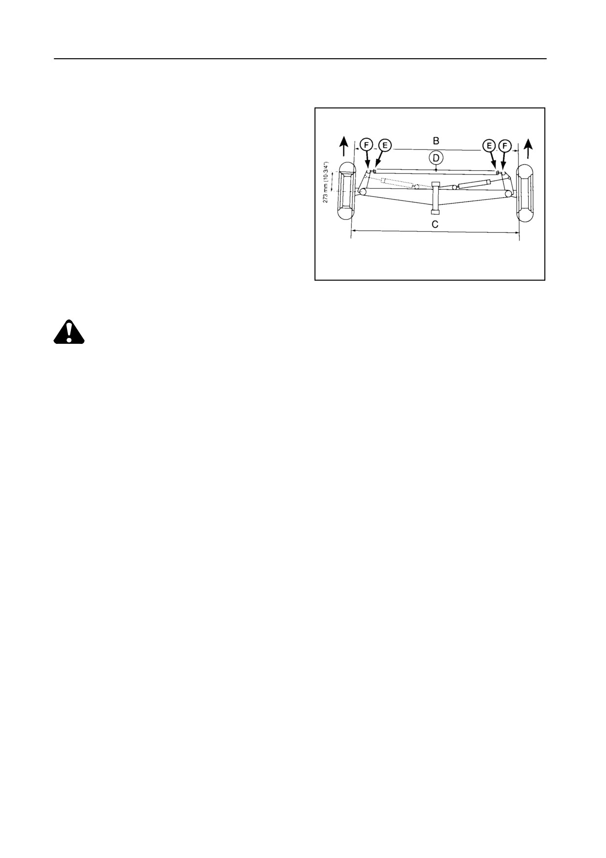
TOE-IN ADJUSTMENT -- Figure 58 (aerial view)
The steering wheels should have the correct amount
of toe-in, otherwise premature tyre wear may occur.
The distance between the steering wheels must be
smaller at the front than at the rear (facing the direc-
tion of travel).
To check and adjust the toe-in, proceed as follows:
1. Apply the parking brake and support the steering
axle so that the steering wheels are clear of the
50402
ground.
58
CAUTION:
Use suitable jack stands, securely posi-
tioned underneath the rear of the ma-
chine, before adjusting the steering axle.
Steering ball joints, wheel spindles, tie
rods and steering hydraulic components
should be checked every 50 hours of op-
eration.
2. Set the steering wheels in the straight ahead posi-
tion.
3. Mark spots at 273 mm from the centre on the front
inside of the wheel rims at the centre-of-wheel
height and measure distance B.
4. Turn the steering wheels 180_ forward or rear-
ward until the marks are at the centre-of-wheel
height and measure distance C.
Distance C must be 8 to 12 mm greater than dis-
tance B.
5. To adjust the toe-in, loosen jam nuts E, remove
steering ball F out of the steering arm and turn
the steering ball in or out rod D evenly on both
sides. After adjustment, tighten the slotted nut of
steering balls F and the jam nuts E (see further in
this Section).
5-29
ADJUSTMENTS AND MAINTENANCE
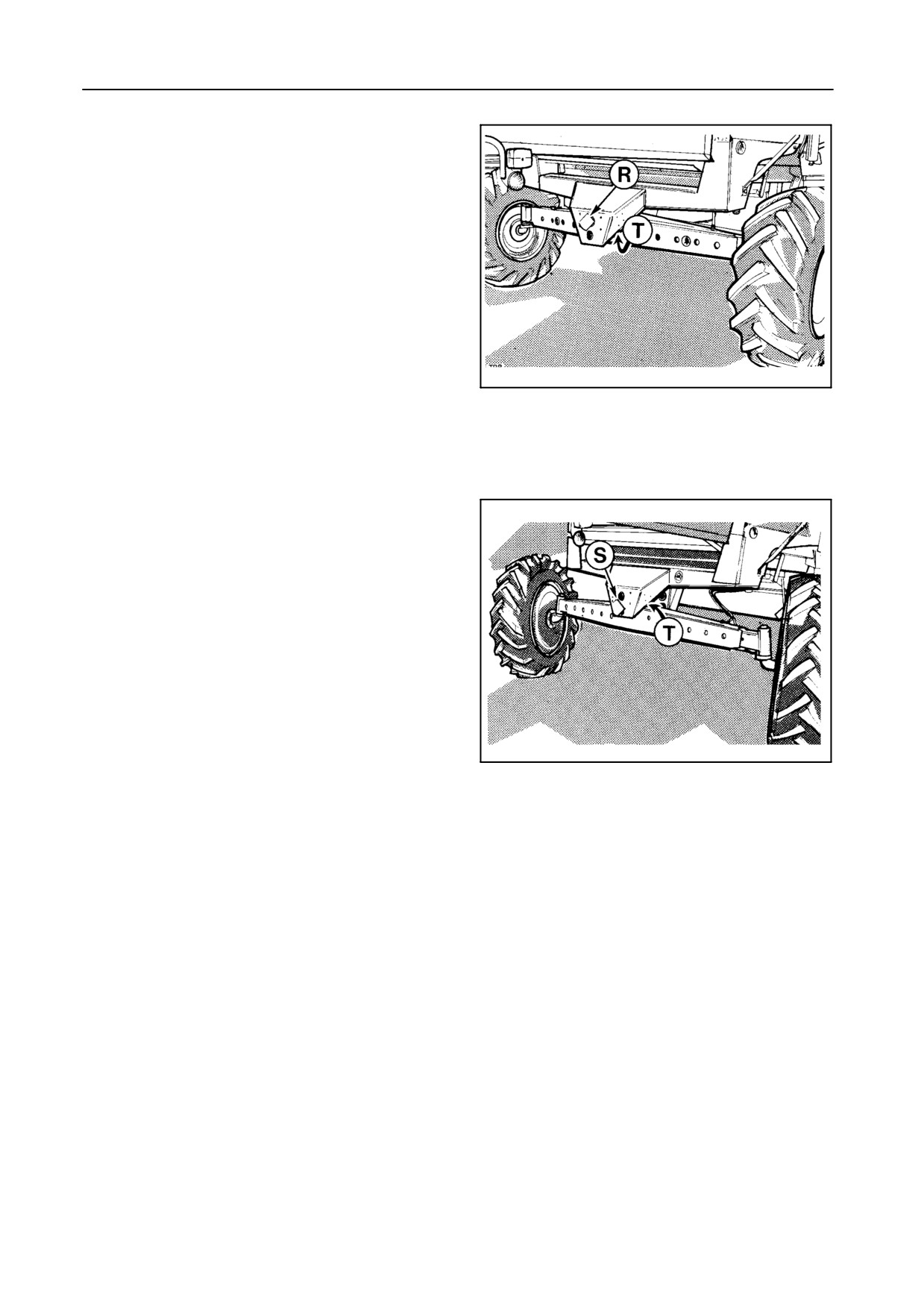
STEERING AXLE POSITION -- Figures 59 and 60
When operating on standard steering wheels, the
steering axle should be installed in the upper hole R in
the frame and, in the case of an adjustable steering
axle, in the front position (long bushing T is fitted at
the rear of the steering axle).
When operating on tracks and rice steering wheels or
for the TX67 combine, the steering axle should be
fitted in the lower hole S in the frame and, in the case
of an adjustable steering axle, in the rear position
(long bushing T is fitted at the front of the steering
21122
axle).
59
We recommend this job to be carried out by your New
Holland dealer.
21125
60
5-30
SECTION 5
FIXED STEERING AXLE
Adjustment
Adjust the toe-in as described in the previous para-
graph
Steering wheel stops -- Figure 61
The steering wheel stops are factory-set and should
normally not require further adjustment.
42900
61
If, for any reason, the stops require adjustment, pro-
ceed as follows:
1. Turn bolt E completely in.
2. Rotate the steering wheel to the extreme left or
right-hand position so that the steering cylinder is
at the end of its stroke.
3. Retract the steering cylinder 2 mm.
4. Turn bolt E against the support and tighten the
lock nut.
5. Proceed in the same way on the opposite side.
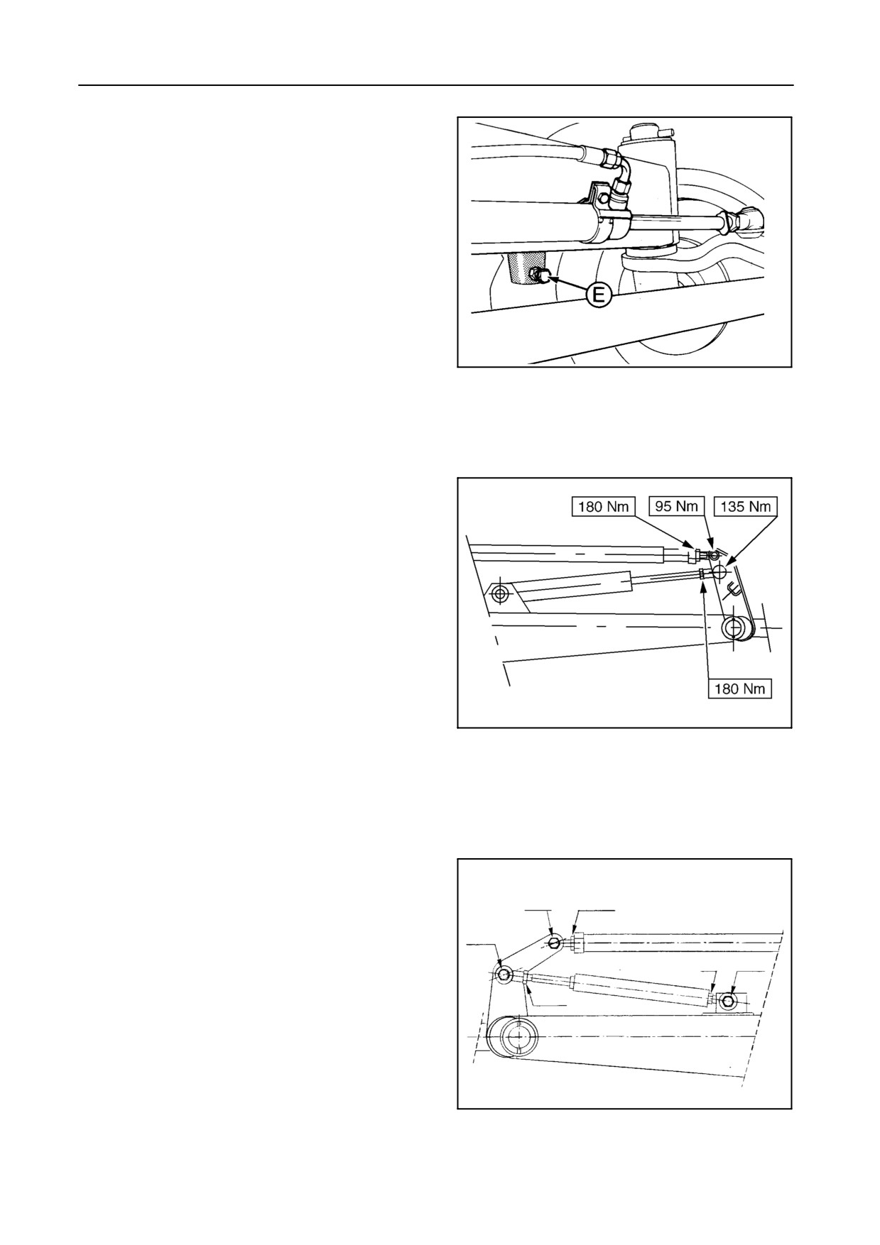
Steering ball joints -- Figures 62 and 63
43183
Check the steering ball joints of the steering axle
62
TX62-63-64PLUS-65PLUS
every 50 hours of operation for correct nut torque or
possible play.
If, for any reason, the steering ball joints were disas-
sembled, the nut torque should be as mentioned in
Figure 62 for models TX62-63-64PLUS-65PLUS, or in
Figure 63 for models TX67-68-68PLUS.
115 Nm
135 Nm
115 Nm
135 Nm
115 Nm
135 Nm
52534
TX67-68-68PLUS
63
5-31
ADJUSTMENTS AND MAINTENANCE
ADJUSTABLE STEERING AXLE [if fitted] --
Figures 64 and 65
The adjustable steering axle has three positions:
S Narrow position
NOTE:
This position is mandatory in Germany for
road transport
S Mid position
51678
S Wide position
64
Adjustment
CAUTION:
Use suitable jack stands, securely posi-
tioned underneath the rear of the ma-
chine, before adjusting the steering axle.
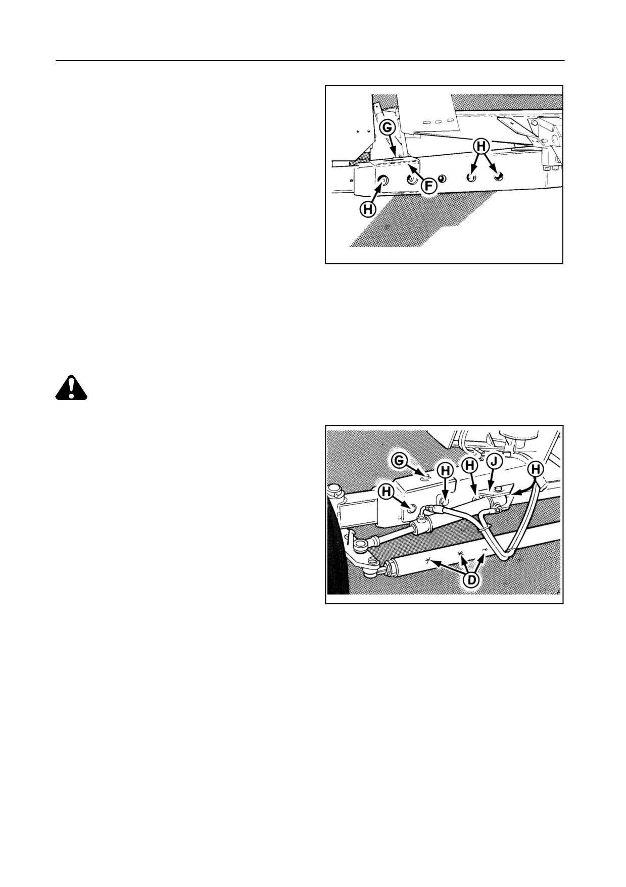
Proceed as follows:
1. Apply the parking brake and support the steering
axle on the left-hand side.
2. Loosen bolt G and hammer it towards the centre
of the axle, so that key F is loose.
3. Remove the bolts from tie rod D and bolts H from
51679
the steering axle.
65
4. Adjust the steering axle on the left-hand side to
the required width.
5. Reinstall bolts H.
6. Hammer bolt G to the outside, so that key F is
fixed, and tighten bolt G to 137 Nm.
7. Tighten bolts H to 294 Nm.
8. Support the steering axle on the right-hand side
and adjust, as outlined above.
5-32
SECTION 5
9. Reinstall the steering cylinder support J in the
correct position.
10. Reinstall the bolts in the tie rod.
Adjust the toe-in as described in the previous para-
graph.
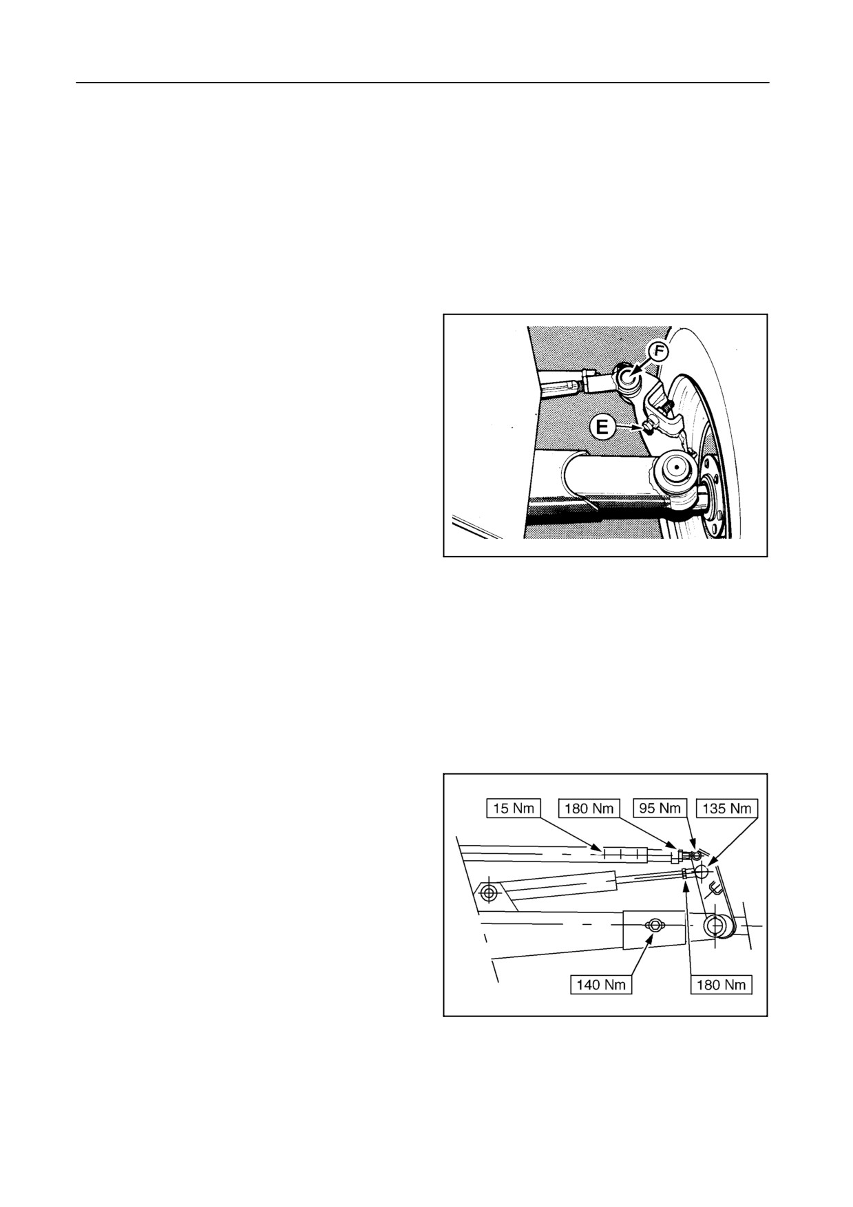
Steering wheel stops -- Figure 66
The steering wheel stops are factory-set and should
normally not require further adjustment.
If, for any reason, the stops require adjustment, pro-
ceed as follows:
1. Turn bolt E completely in.
2. Rotate the steering wheel to the extreme left or
right-hand position so that the steering cylinder is
at the end of its stroke.
21117
66
3. Retract the steering cylinder 2 mm.
4. Turn bolt E against the support and tighten the
lock nut.
5. Proceed in the same way on the opposite side.
Steering ball joints -- Figure 67
Check the steering ball joints of the steering axle
every 50 hours of operation for correct nut torque or
possible play.
If, for any reason, the steering ball joints were disas-
sembled, the nut torque should be as mentioned in
Figure 67.
43184
67
5-33
ADJUSTMENTS AND MAINTENANCE
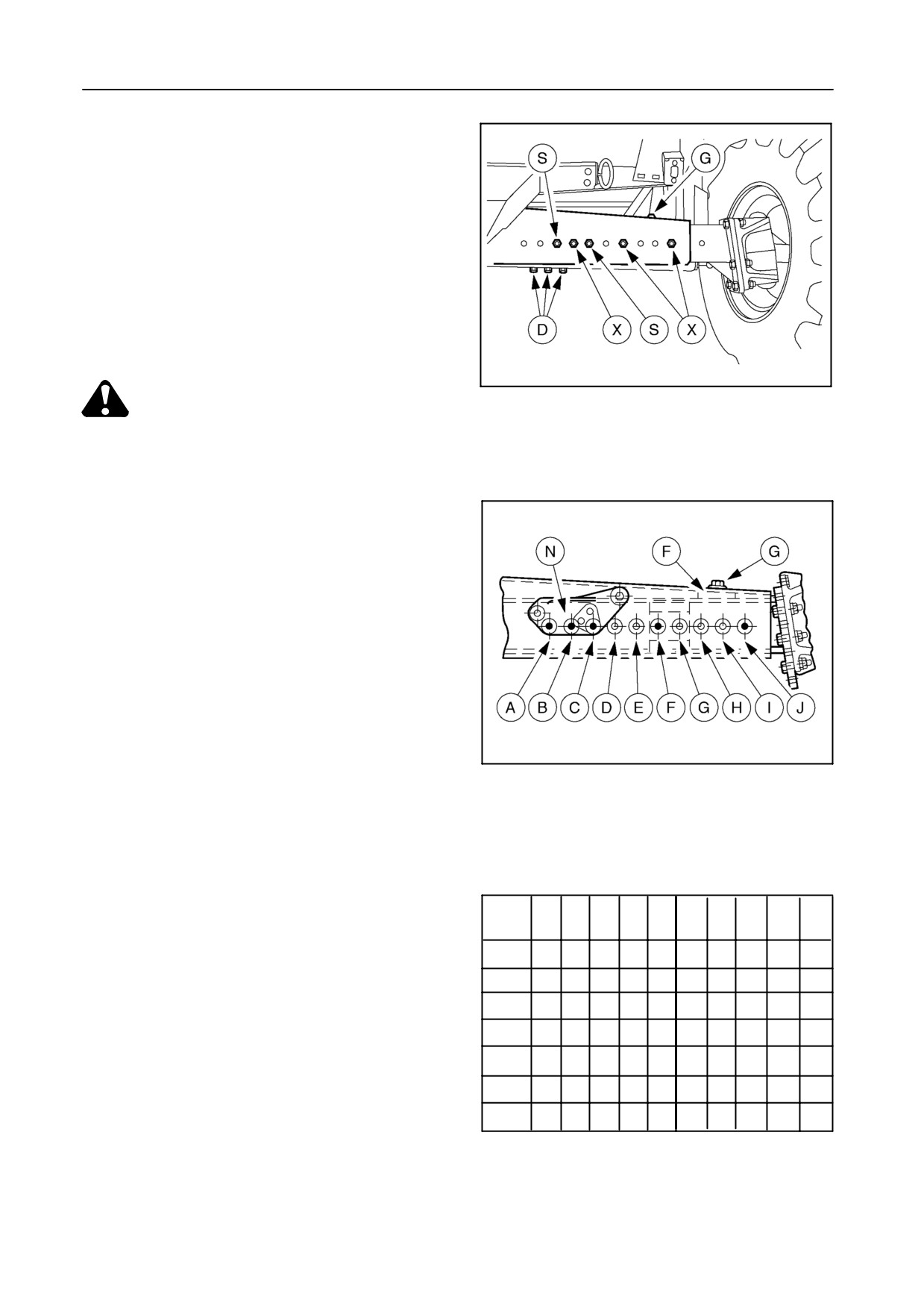
HEAVY-DUTY ADJUSTABLE STEERING AXLE
[if fitted] -- Figure 68 to 70
The heavy-duty adjustable steering axle has 7 posi-
tions.
Adjustment
54780
68
CAUTION:
Use suitable jack stands, securely posi-
tioned underneath the rear of the ma-
chine, before adjusting the steering axle.
Proceed as follows:
1. Apply the parking brake and support the steering
axle on the left-hand side.
2. Loosen bolt G and hammer it towards the centre
of the axle, so that key F is loose.
3. Remove bolts D from the tie rod, and bolts S and
X from the steering axle.
54781
4. Adjust the steering axle on the left-hand side to
69
the required width.
5. Reinstall bolts X. Refer to Figures 69 and 70.
6. Reinstall the steering cylinder support in the cor-
rect position with bolts S.
Hole
A
B
C
D
E
F
G
H
I
J
Posit.
7. Hammer bolt G to the outside, so that the key F is
0
S
X
S
X
X
fixed, and tighten bolt G to 140 Nm.
1
S
X
S
X
X
8. Tighten bolts S and X to 485 Nm.
2
S
X
S
X
X
3
X
S
S
X
X
9. Support the steering axle on the right-hand side
4
X
S
X
S
X
and adjust, as outlined above.
5
X
S
X
S
X
6
X
S
X
S
X
10. Reinstall bolts D in the tie rod.
70
Adjust the toe-in as described previously.
5-34
SECTION 5
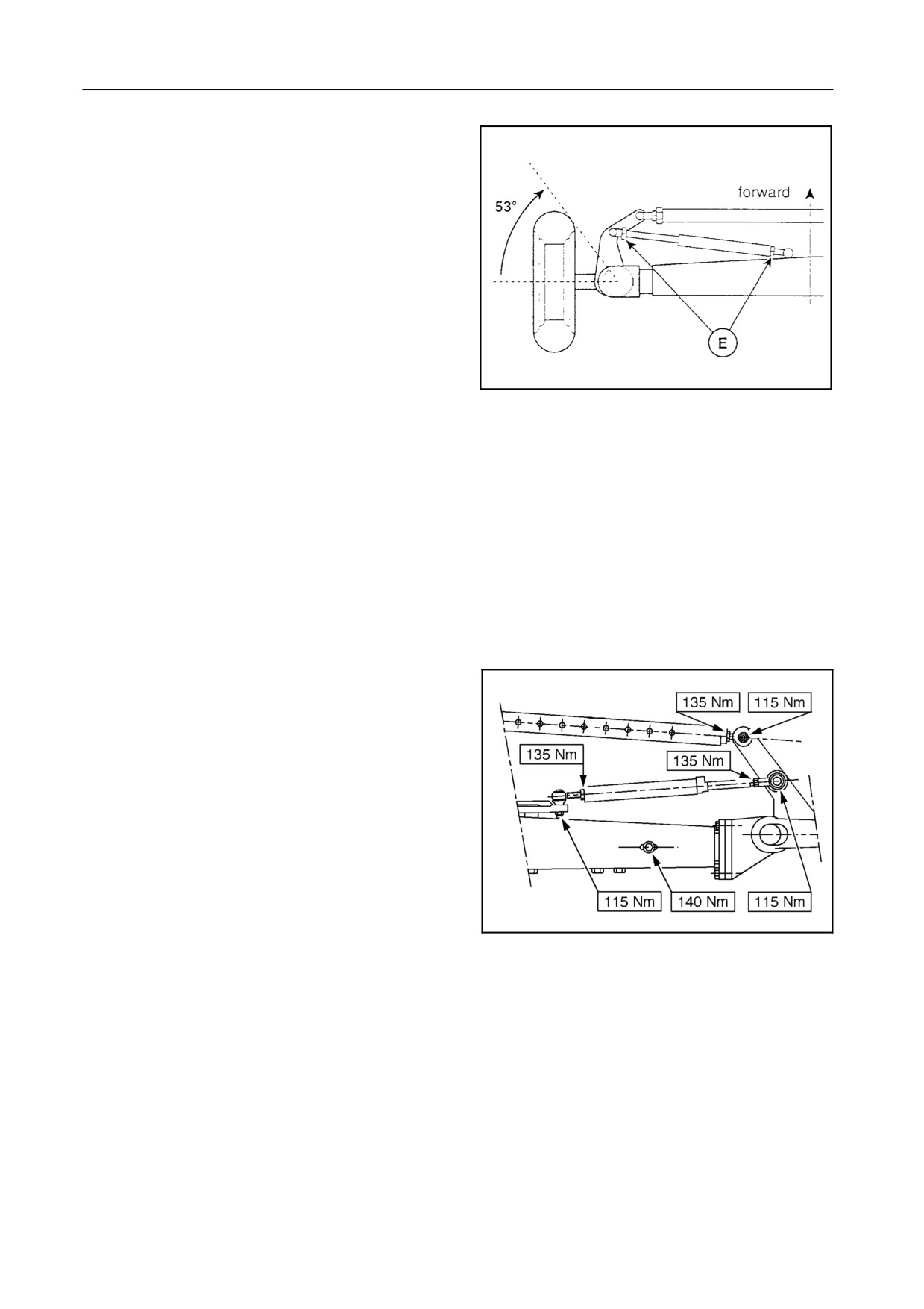
Steering wheel stops -- Figure 71
The steering wheel stops, i.e. the minimum stroke
length of the cylinders, are factory-set and need no
further adjustment.
If, for any reason, the stops require adjustment, pro-
ceed as follows:
1. Rotate the steering wheel to the extreme right-
hand position so that the steering cylinder is at its
minimum stroke. Be sure the opposite cylinder is
55435
not blocking first.
71
2. Adjust 53° with nuts E.
3. Proceed in the same way on the opposite side.
Steering ball joints -- Figure 72
Check the steering ball joints of the steering axle
every 50 hours of operation for correct nut torque or
possible play.
If, for any reason, the steering ball joints were disas-
sembled, the nut torque should be as mentioned in
Figure 72.
52636
72
5-35
ADJUSTMENTS AND MAINTENANCE
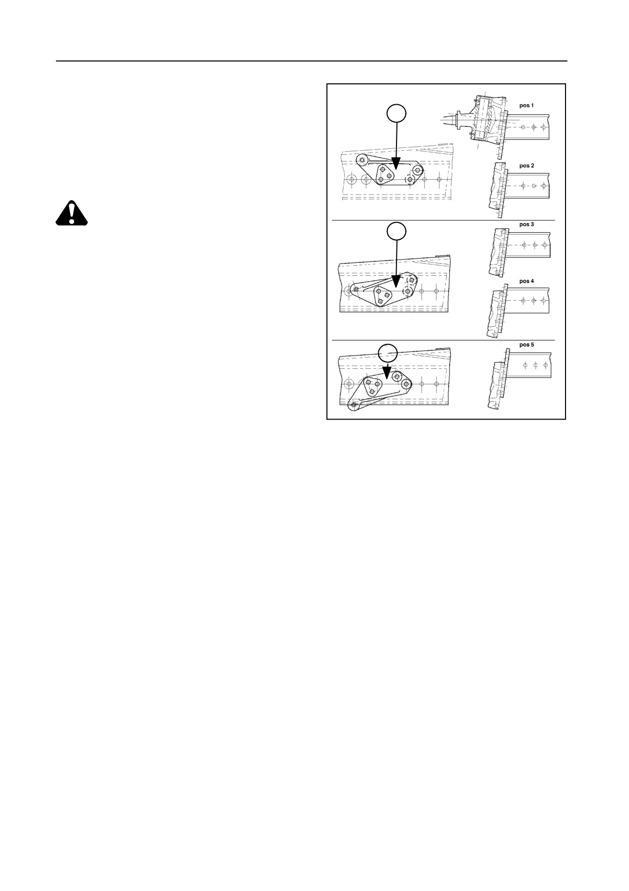
Rear-wheel position -- Figure 73
The complete steering wheel can be repositioned on
N
the steering axle in order to lift the machine rear end
to a level combine position.
Figure 73 shows the five different positions. Install
steering cilinder support N in the correct position.
CAUTION:
N
Wheel drive assemblies are heavy. Use a
lifting device of adequate capacity. Re-
position one side at a time.
The bolts should be tightened to 485 Nm.
Adjust the toe-in as described previously.
N
43172
73
5-36
SECTION 5
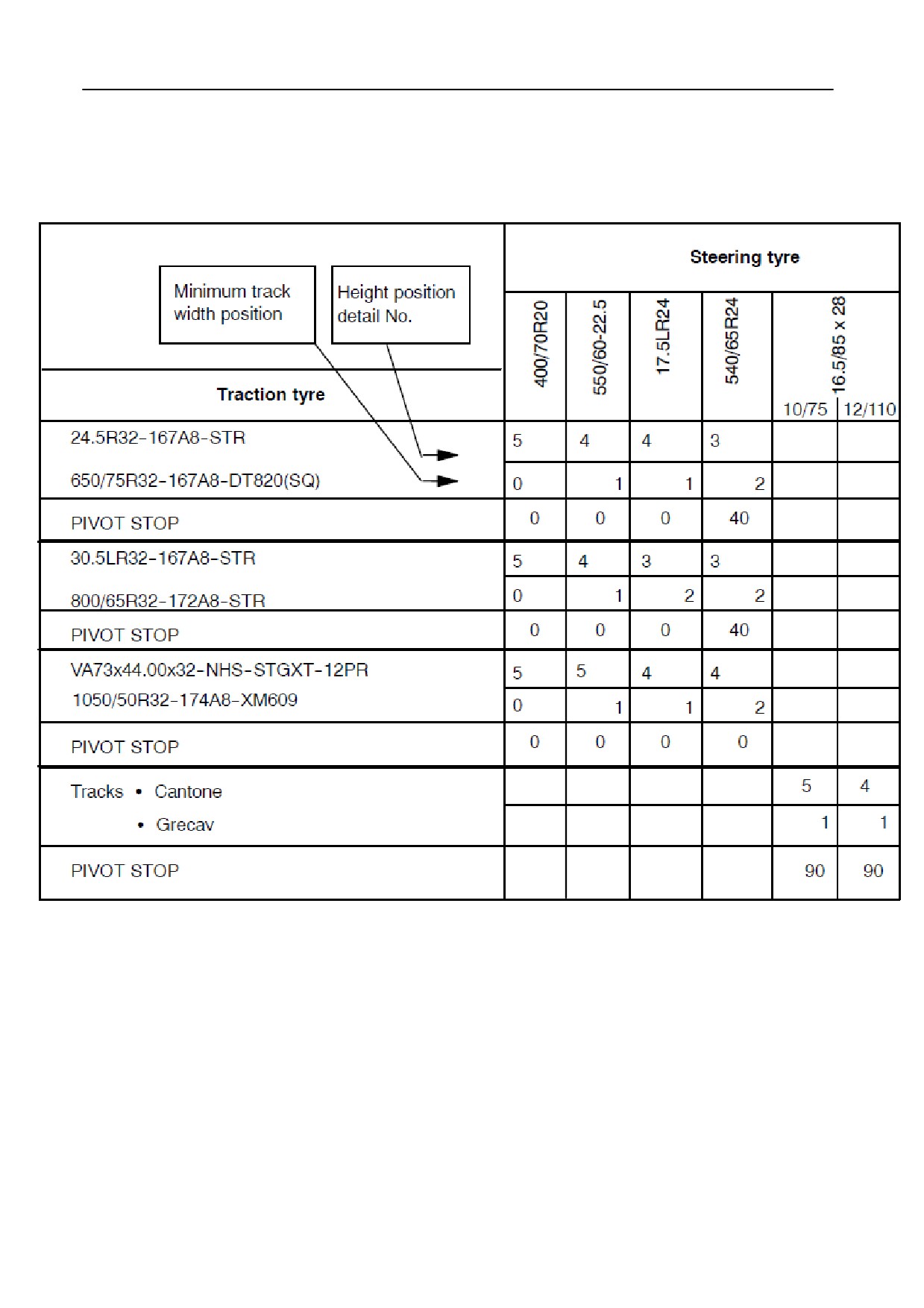
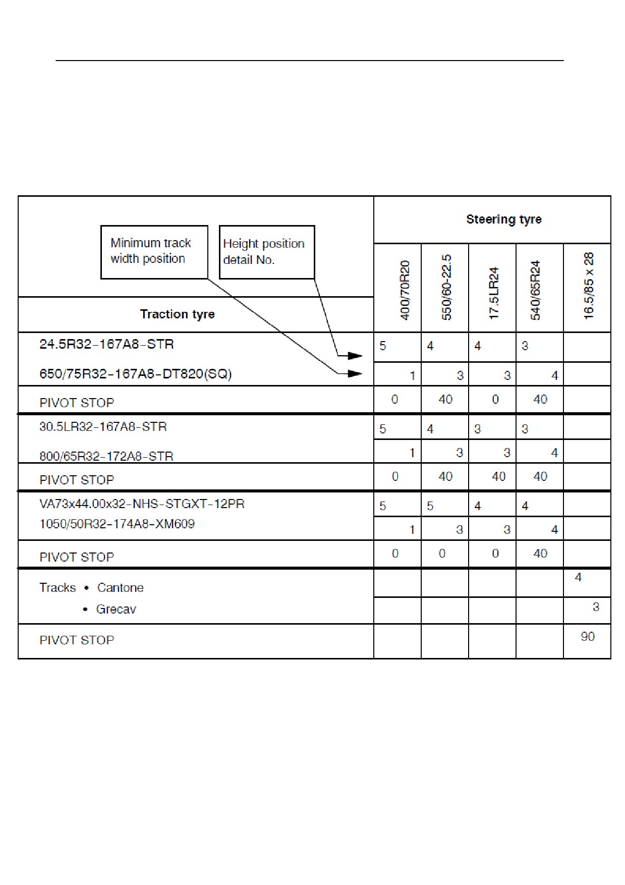
ASSEMBLY POSITION OF STEERING ARM ASSEMBLY AND MINIMUM TRACK WIDTH POSITION
Models TX62-63-64PLUS-65PLUS
5-37
ADJUSTMENTS AND MAINTENANCE
ASSEMBLY POSITION OF STEERING ARM ASSEMBLY AND MINIMUM TRACK WIDTH POSITION
Models TX66-67-68-68PLUS
5-38
SECTION 5
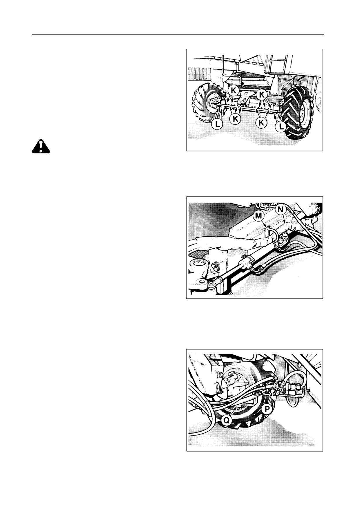
REAR-WHEEL DRIVEN STEERING AXLE
[if fitted]
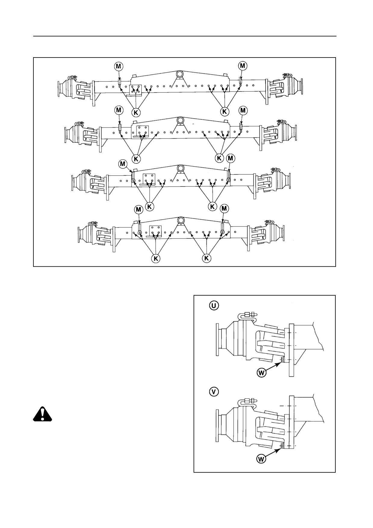
This steering axle has four positions -- Figure 77
Adjustment -- Figures 74 to 77
21149
CAUTION:
74
Use suitable jack stands, securely posi-
tioned underneath the rear of the ma-
chine, before adjusting the steering axle.
Proceed as follows:
1.
Apply the parking brake and support the steering
axle on the left-hand side.
2.
Remove the five left-hand bolts K and the four
bolts L from the track rod.
3.
Adjust the steering axle on the left-hand side to
the required width.
21148
4.
Place the hydraulic hoses support M in the re-
75
quired position, as shown.
5.
Reinstall bolts K and tighten them to 360 Nm.
6.
Support the steering axle on the right-hand side
and adjust, as outlined above.
7.
Install the steering cylinder support N in the cor-
rect position.
8.
Reinstall the bolts in track rod L.
9.
Adjust the toe-in, as described previously.
NOTE:
Check if the routing of the hydraulic hoses is
satisfactory and reposition valve P on its sup-
21147
port Q, as necessary.
76
5-39
ADJUSTMENTS AND MAINTENANCE
51594
77
Rear-wheel position -- Figure 78
When operating on tracks, the complete steering
wheel and hydrostatic motor can be repositioned
on the steering axle in order to lift the machine
rear end to a level combine position.
Figure 78 shows the standard clearance position
U and the high clearance position V, when tracks
are used.
CAUTION:
Wheel drive assemblies are extremely
heavy. Use a lifting device of adequate
capacity. Reposition one side at a time.
51595
The bolts W should be tightened to 440 Nm.
78
5-40
SECTION 5
ENGINE
IMPORTANT:
Clean the engine area, the radiator compart-
ment and, in particular, the exhaust system
daily to prevent fire hazards. When operating
in extremely dry crops and in heavy dust
conditions, check these areas more often and
clean, if necessary.
FUEL SYSTEM
Fuel level
The fuel level can be checked on the gauge in the in-
strument panel.
Filling the fuel tank
Before filling the fuel tank, clean away any dust and
chaff from the filler neck and fill through a funnel with
a fine gauze filter.
The best time to fill the tank is in the evening as this
prevents overnight condensation from forming in the
tank.
IMPORTANT:
The quality of fuel used is an important factor
in obtaining dependable performance and sat-
isfactory engine life. Many engine difficulties
can be traced to dirty fuel, therefore the impor-
tance of using clean fuel, properly stored, can-
not be stressed too strongly.
Fuel with a sulphur content below 0.5 % is rec-
ommended.
5-41
ADJUSTMENTS AND MAINTENANCE
CAUTION:
S Handle fuel with care.
S Never fill the tank when the engine is
running.
S Smoking is strictly prohibited during
filling.
S Always clean up spilled fuel.
IMPORTANT:
The fuel tank is vented through the filler cap. If
a new filler cap is required, always replace it
with an original vented cap.
Fuel tank capacity
Models TX62-63-64PLUS
: 450 litres
Models TX65PLUS-66-67-68-68PLUS
: 600 litres
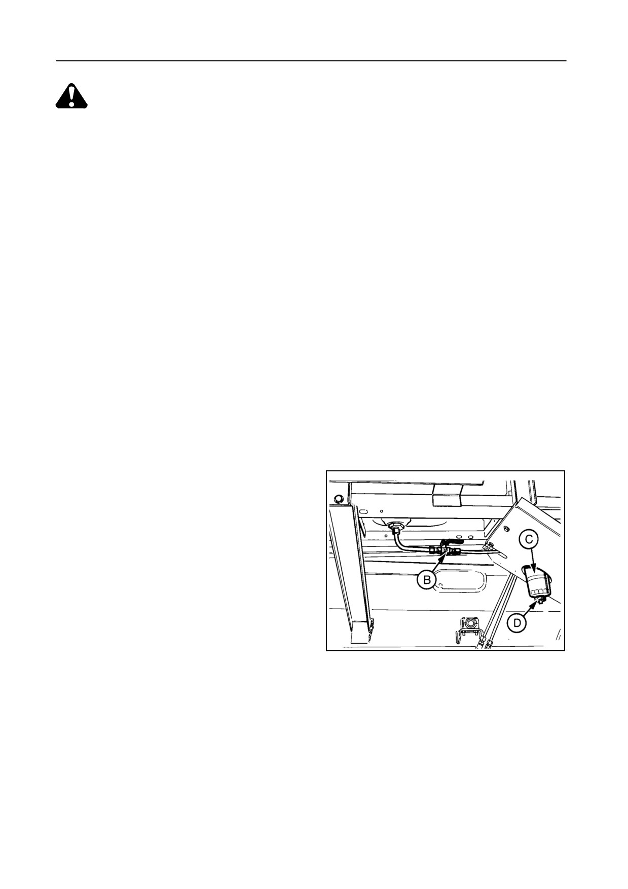
Fuel prefilter/ water separator -- Figure 79
Drain the water from the filter housing daily by loos-
ening screw D until fuel free of water runs out of the
screw orifice. Collect the water/fuel mixture and dis-
pose of according to regulations. Retighten screw D.
Change the fuel prefilter/water separator C every 400
hours of operation, or earlier, if a drop in engine per-
formance is experienced.
To change the fuel prefilter/water separator, proceed
as follows:
55034
1. Shut off cock B.
79
2. Unscrew the ‘‘spin-on’’ prefilter/water separator.
3. Apply a film of oil to the gasket of the new prefilter/
water separator.
4. Screw on the new prefilter/water separator by
hand until it contacts the filter head. Tighten fur-
ther maximum half a turn.
DO NOT USE TOOLS!
5-42
SECTION 5
Fuel filters
Models TX62-63-64PLUS-65PLUS-66-67 -- Figure 80
Models TX68-68PLUS -- Figure 81
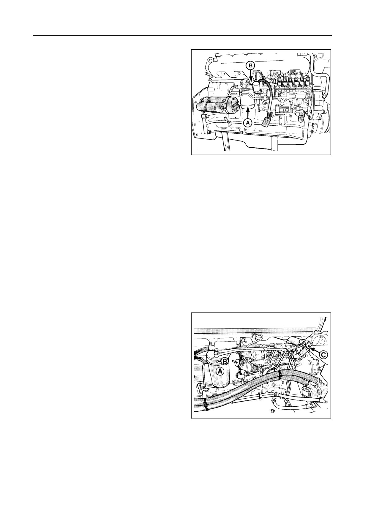
The fuel filter A is a paper element ‘‘spin-on’’ filter
which must be replaced every 200 operating hours.
To change the fuel filter, proceed as follows:
1. Unscrew the fuel filter using a filter wrench.
2. Fill the new filter with clean fuel and coat the seal
30227
with fuel. Ensure the seal is properly seated.
80
TX62-63-64PLUS-65PLUS-66-67
3. Screw the filter on by hand and tighten it securely
(firmly against the head and then an additional 1/4
to 1/2 turn).
4. Bleed the fuel system (refer to the next para-
graph).
5. Models TX62-63-64PLUS-65PLUS-66-67:
The fuel filter contains a sediment bowl at its bot-
tom side which collects large particles of dirt and
water. This sediment bowl can be removed and
cleaned.
Bleeding the fuel system
Models TX62-63-64PLUS-65PLUS-66-67 -- Figure 80
Models TX68-68PLUS -- Figure 81
Proceed as follows:
1. Ensure there is fuel in the tank.
2. Loosen bleed screw B on the top of the fuel filter
housing.
3. Models TX68-68PLUS only:
30230
Loosen knurled knob C of the fuel lift pump.
81
TX68-68PLUS
4. Operate the fuel lift pump piston by hand until the
fuel escaping is free from air bubbles.
5. Retighten bleed screw B.
5-43
ADJUSTMENTS AND MAINTENANCE
6. Continue pumping until the force needed remains
more or less constant. This allows the fuel to be
drawn into the injection pump.
7. Models TX68-68PLUS only:
Press the fuel lift pump piston down and firmly
tighten knurled knob C.
NOTE:
If the engine does not start after performing
the above procedure, it will be necessary to
bleed the fuel injector lines while starting the
engine.
This will allow any air to escape that may be in
the high pressure part of the fuel system.
Take all necessary safety precautions when
working on the engine. Do not bleed the lines
when the engine is warm.
Fuel injection pump and injectors
As the fuel injectors and fuel injection pump have to
be set very accurately on specialized equipment, we
strongly recommend that any repairs on these parts
are carried out by your New Holland dealer.
COOLING SYSTEM
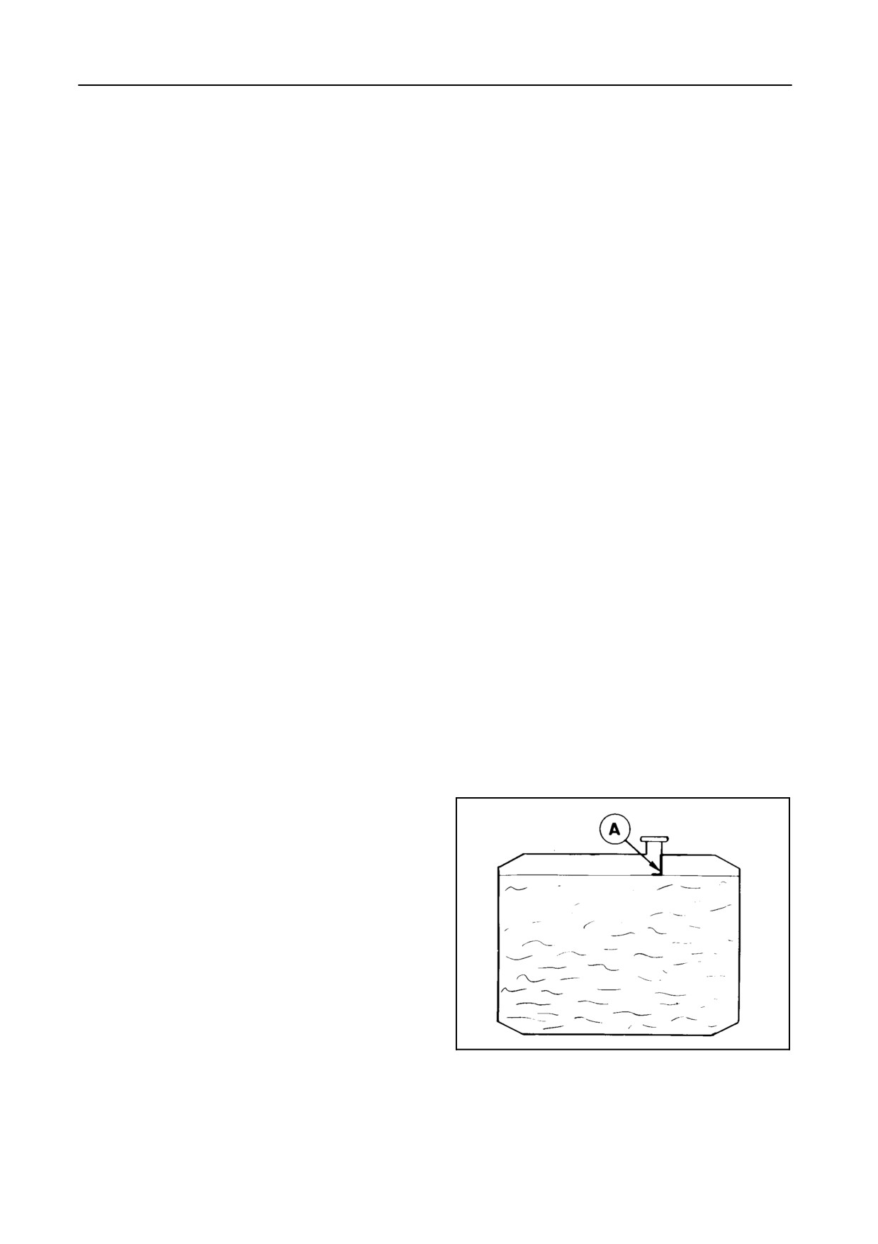
Coolant level -- Figure 82
Daily check the radiator coolant level on the level indi-
cator A when the engine is cold.
ATTENTION:
Under no circumstances should the engine be
started without water in the cooling system.
If the temperature rises too high during operation, or
if the audible alarm sounds, stop the engine immedi-
51514
ately and locate the cause (coolant level, oil level, fan
82
and rotary dust screen belt tension, dirty radiator or
rotary dust screen, etc.). Refer to Section 6 - TROU-
BLESHOOTING.
5-44
SECTION 5
WARNING:
S Take care if removing the radiator cap
when the engine is hot. Cover the cap
with a rag and turn slowly to release
the pressure before removing the cap
completely.
S Do not add cold water to a hot radia-
tor.
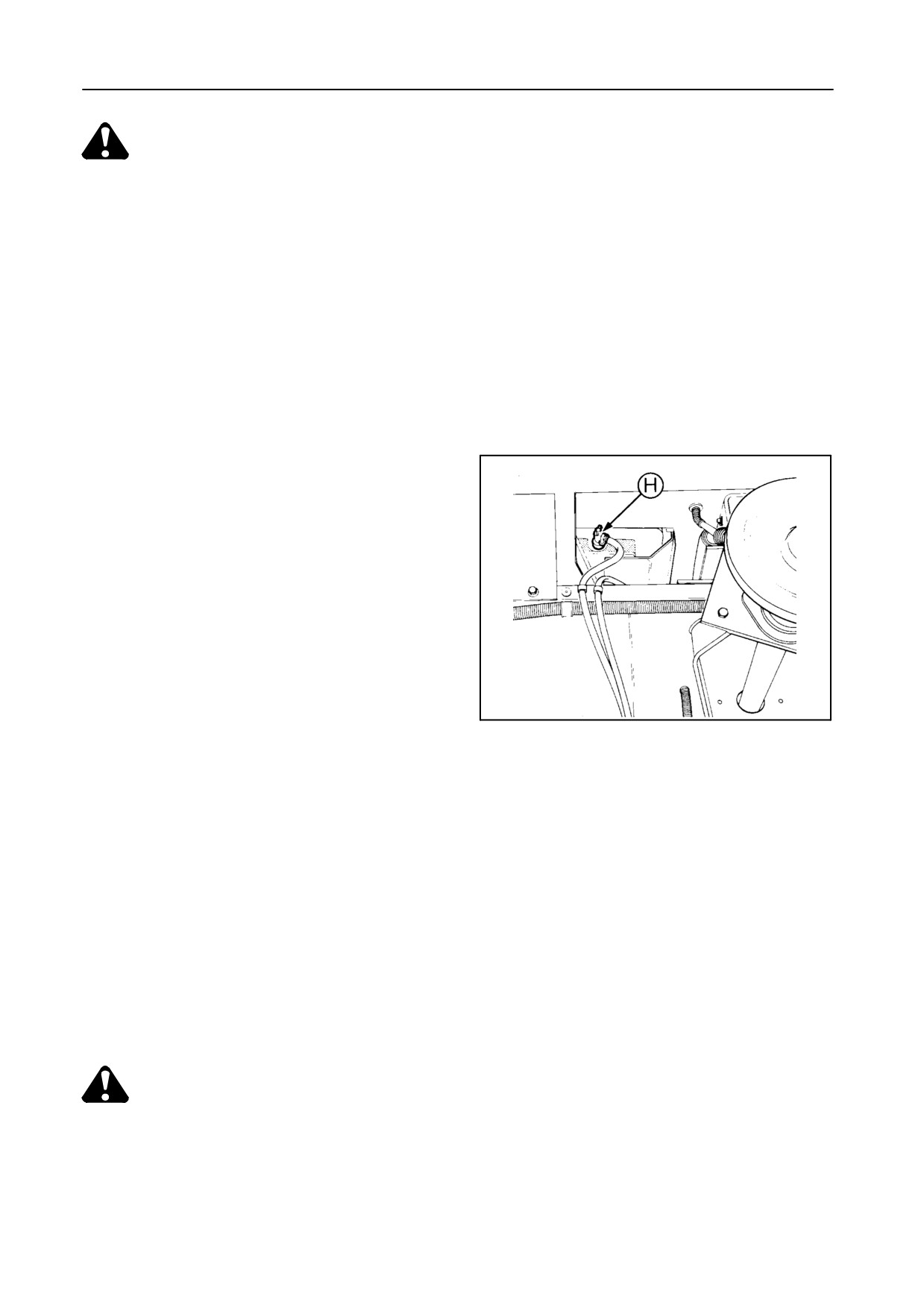
Coolant change -- Figure 83
The coolant water/antifreeze mixture should be re-
newed:
S every 600 operating hours, or
S every 2 years, whichever comes first.
When replacing the coolant, proceed as follows:
42896
83
1. Drain the cooling system by opening cock H.
2. Flush the cooling system by closing cock H and
filling the system with clean water. Start the en-
gine and bring it up to normal operating tempera-
ture. Stop the engine. Then open cock H.
3. Close cock H and fill the cooling system with cool-
ant as specified.
CAUTION:
The engine and radiator are hot, so ex-
treme care should be taken when filling
the radiator and reinstalling the cap.
5-45
ADJUSTMENTS AND MAINTENANCE
To remove air from the system, proceed as follows:
1. Fill the radiator to the bottom of the filler neck.
Leave the radiator cap off.
2. Start the engine and vary the rpm between low
idle and 1500 rpm for 3 minutes.
3. Increase the rpm to maximum until the thermostat
opens (upper radiator hose becomes hot), and
then for a further 10 minutes to allow the air to es-
cape.
4. Return to idle and stop the engine after 1 minute
(turbocharger precaution!).
5. Fill the radiator to the level indicator A (Fig. 82)
and reinstall the radiator cap.
Coolant system capacity
35 litres
Coolant specification
S
47.5 % water
S
47.5 % antifreeze
S
5% conditioner
The quality of water should not exceed the following
limits:
S Total hardness: 0.3 %
S Chlorides : 0.1 %
S Sulphates : 0.1 %
Antifreeze: AGRIFLU (ref. NH900A)
Conditioner: NALCOOL3000 ESE-M99B169-A
5-46
SECTION 5
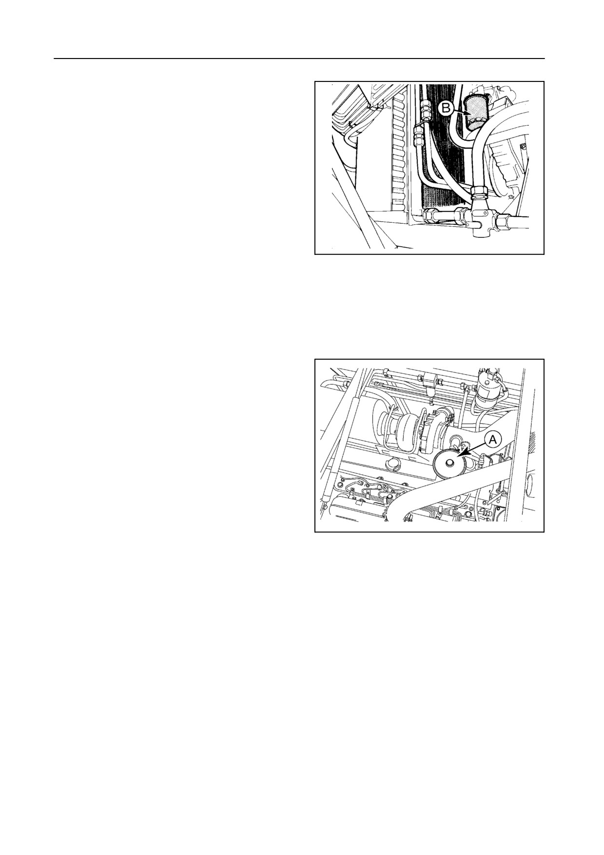
Water conditioner element B
[Model TX68-68PLUS only] -- Figure 84
Replace the element every 400 operating hours or
once a year, whichever comes first.
42932
84
CRANKCASE BREATHING SYSTEM -- Figure 85
The crankcase is vented through the valve cover and
housing A to the inlet tube.
The crankcase breathing system does not need to be
serviced.
30837
85
CYLINDER HEAD BOLTS
The cylinder head bolts do not require retightening
during normal service intervals.
5-47
ADJUSTMENTS AND MAINTENANCE
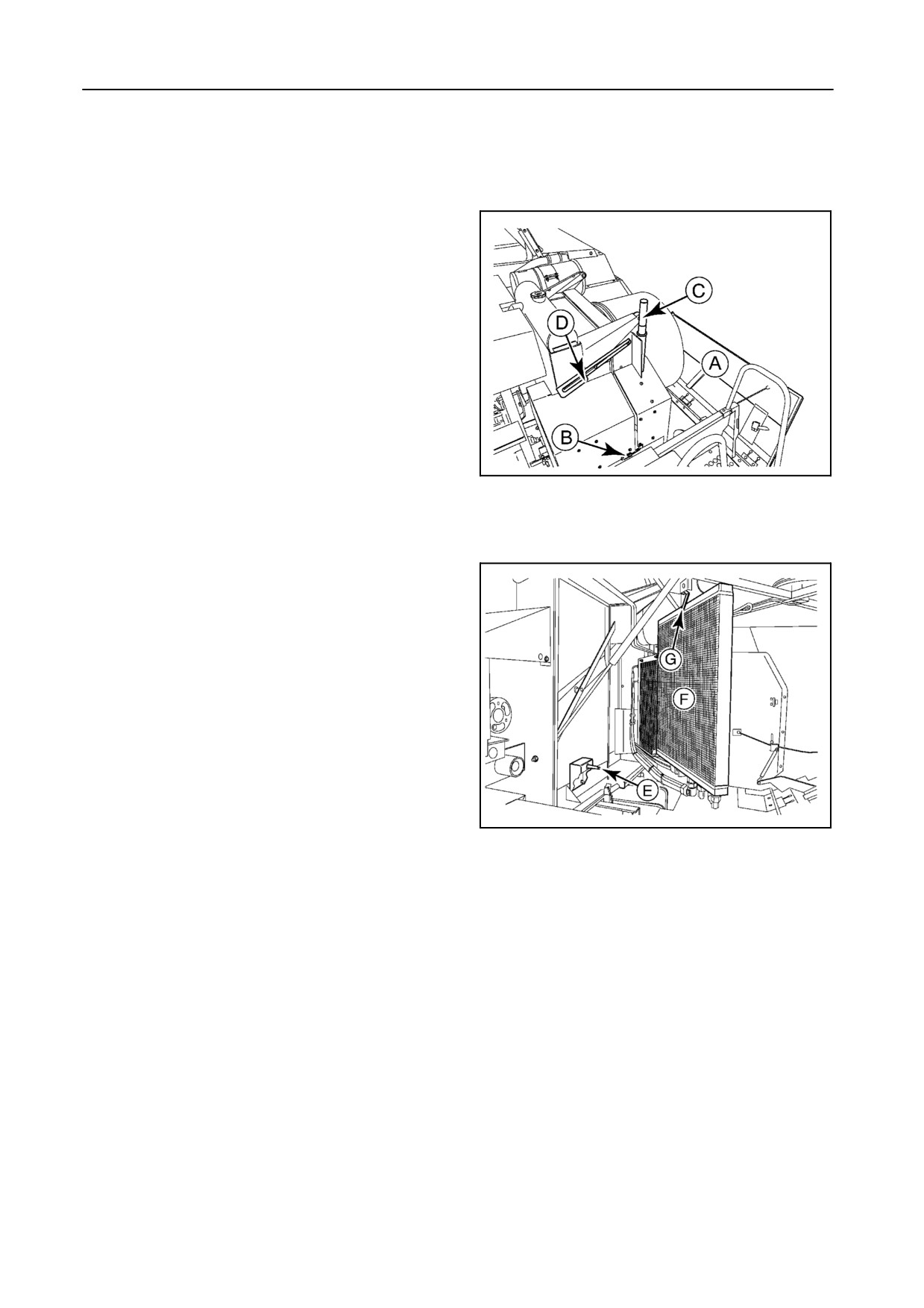
ROTARY DUST SCREEN AND COOLING SYSTEM -- Figures 86 and 87
All TX Series models (except for TX68) have a
hinged rotary dust screen door.
To gain access to clean the cooling system, proceed
as follows:
1. Open safety guard A and lock B.
2. Pull out handle C and open the rotary dust screen
door by pulling handle C until safety latch D is in
position.
30836
3. Remove lynch pin E.
86
4. Pull out the oil coolers and condenser door F.
5. Keep the radiator door open with lock G.
Clean the cooling system regularly, depending on
combining conditions.
30381
87
5-48
SECTION 5
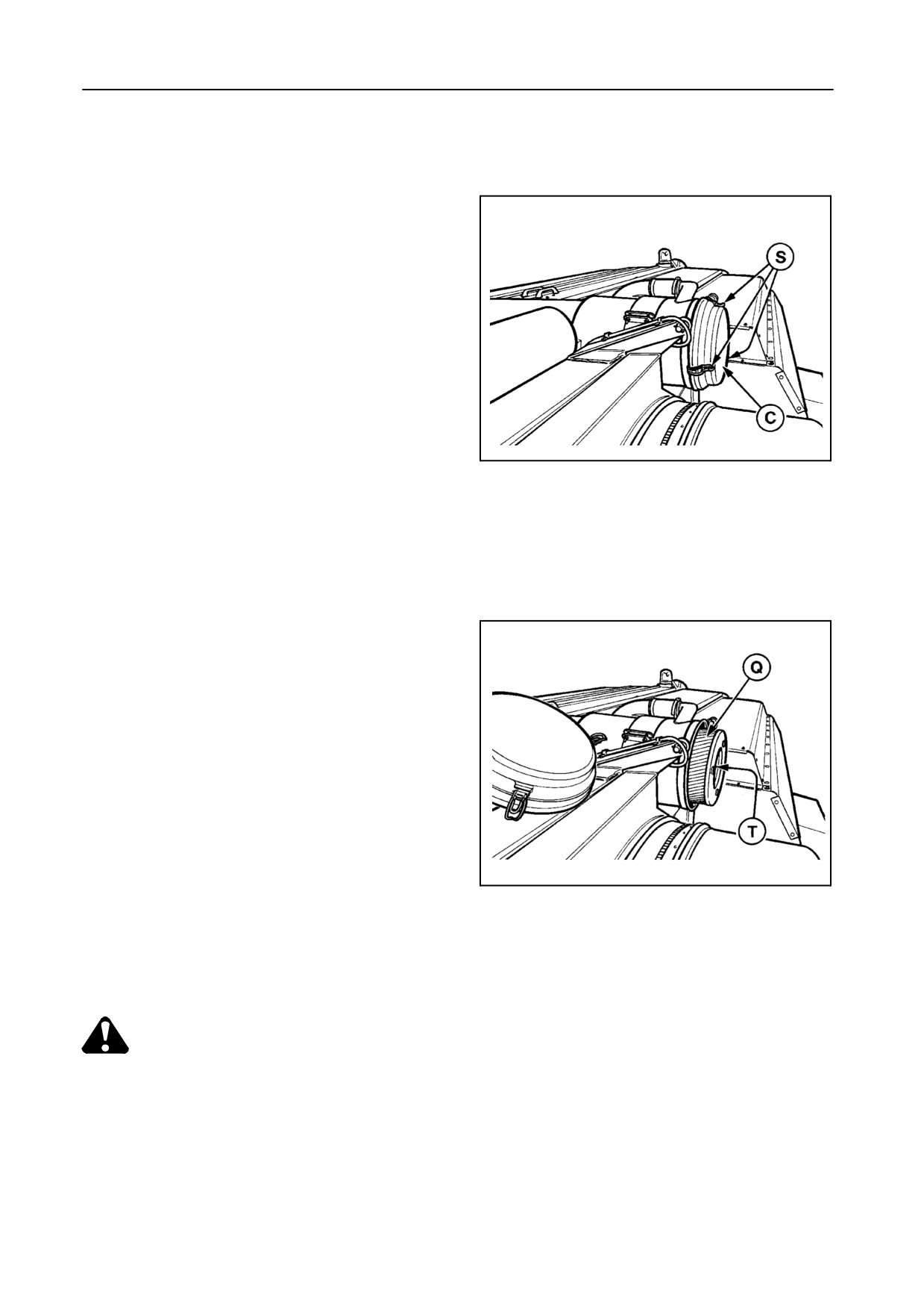
AIR INTAKE SYSTEM -- Figures 88 and 89
The filter element Q should only be cleaned when
the warning light in the combine cab illuminates and
the audible alarm sounds (500 mm vacuum).
To remove the air cleaner element Q, remove cover C
by loosening three clamps S and remove the air
cleaner element.
To clean the element, hold the top and tap it against
the palm of the other hand to remove the dust.
NEVER TAP IT ON A HARD SURFACE.
55498
88
When tapping does not remove the dirt, direct com-
pressed air through the element, from the inside to-
wards the outside.
To prevent damage to the element when cleaning
with compressed air, take the following precautions:
S Maximum air pressure must be 5 bar.
S Move the nozzle up and down while rotating the
element.
55499
89
S Keep the nozzle at least 25 mm from the pleated
paper.
WARNING:
Wear a dust mask when cleaning the air
filter element.
5-49
ADJUSTMENTS AND MAINTENANCE
If the element is soiled with oil or soot, it is possible to
soak it for 15 minutes in a solution of 75 grammes of
non-sudsy detergent and 10 litres of lukewarm water.
Rinse the element thoroughly in clean water until the
water remains clear and leave the element to dry.
NEVER WASH THE AIR CLEANER ELEMENT IN
PETROL OR DIESEL OIL.
Every time the element is cleaned, it should be exam-
ined for holes and cracks by holding an electric light
bulb inside the element and looking through it. If any
damage is noted, discard the element and fit a new
one.
Replace the element after five cleanings or once a
year, whichever comes first.
When fitting, make sure the element is seated prop-
erly and the sealing is in good condition.
A safety element T is fitted as an additional security to
prevent dust from entering the engine when replacing
the standard element. The safety element should
normally not be cleaned.
Replace the safety element every two years.
5-50
SECTION 5
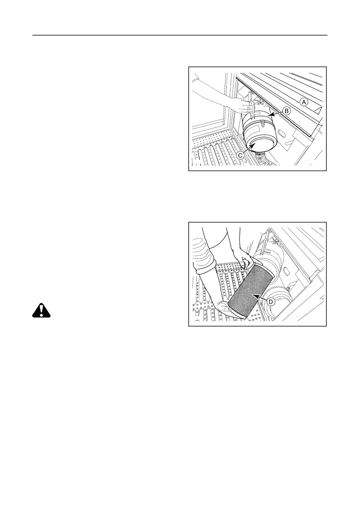
CAB AIR FILTER -- Figures 90 and 91
The cab air filter is located near the cab door on the
left-hand side.
Clean the cab air filter regularly and, in extremely
dusty conditions, daily.
Wear a suitable dust mask!
Proceed as follows:
30830
1. Open cover A.
90
2. Open filter housing B.
3. Remove cover C.
4. Remove the filter element D.
5. Clean with compressed air blown from the inside
towards the outside.
It isadvisibletoreplacethefilterelements everyyear.
CAUTION:
30829
Dust protection
91
The air filter in the cab does not protect
against all substances
(e.g. chemical
residues on crops). Absolute protection
against specific products can only be ob-
tained when the nature of these products
is known and adequate measures are
purposely designed to counter the haz-
ard created by these substances. Even
the use of carbon filters cannot ensure
complete protection.
It goes without saying that correct filter
maintenance and keeping doors and
windows closed is essential.
5-51
ADJUSTMENTS AND MAINTENANCE
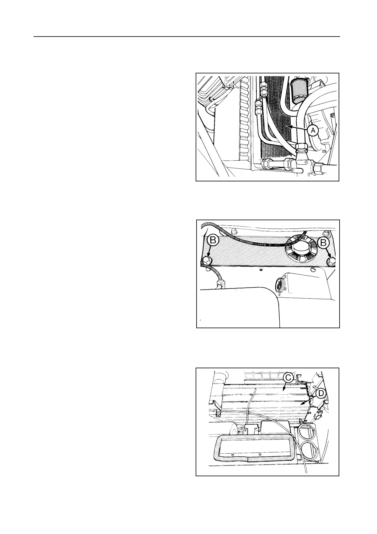
AIR CONDITIONING
CONDENSER -- Figure 92
Regularly inspect and clean the condenser A with
compressed air.
55028
92
EVAPORATOR -- Figures 93 and 94
Inspect and clean the evaporator, if necessary.
Remove two bolts B and tip up the seat to gain ac-
cess to evaporator C, heating radiator D [if installed]
and the ventilation fans.
42895
93
42906
94
5-52
SECTION 5
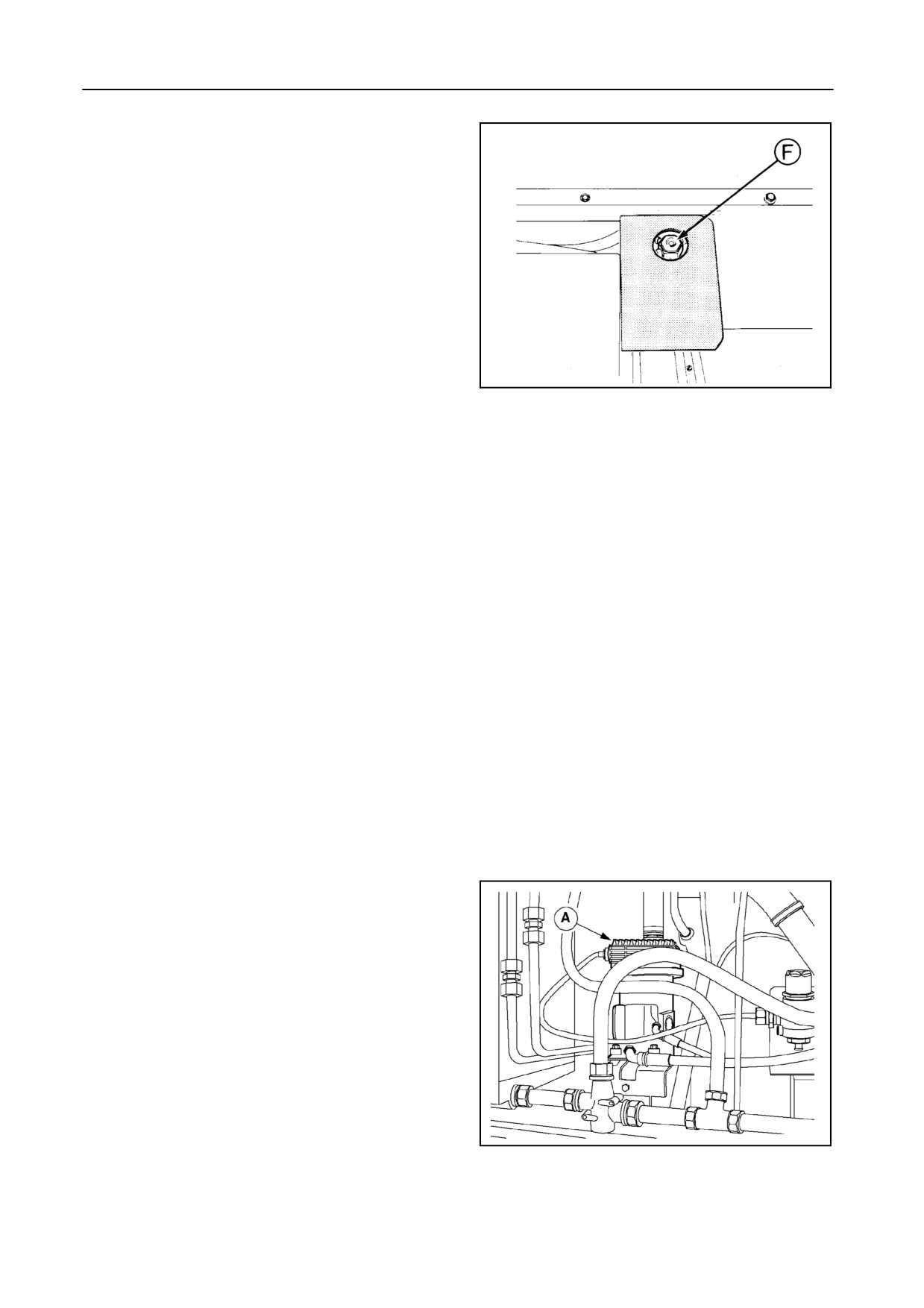
FILTER-DRIER -- Figure 95
A sight glass and a ring-shaped moisture indicator F
on the right-hand side of the engine cover serve for
determining the condition of the R134a gas.
S If therefrigerant iswithout airbubbles, thenthere-
frigerant condition is good.
S If the glass shows a milky refrigerant: satisfactory
performance is ensured.
42899
95
S If air bubbles are visible: lack of refrigerant.
S If the moisture indicator is blue: filter and refriger-
ant are in good condition.
S If the moisture indicator is red: this is an indication
of too much moisture, the filter-drier has to be re-
placed.
If the filter-drier needs to be replaced or if the air con-
ditioning system needs repair, contact your local
dealer.
AIR COMPRESSOR [If installed]
Models TX66-67-68-68PLUS -- Figures 96 to 98
The combine is equipped with an air blowing system
to keep the engine compartment clean.
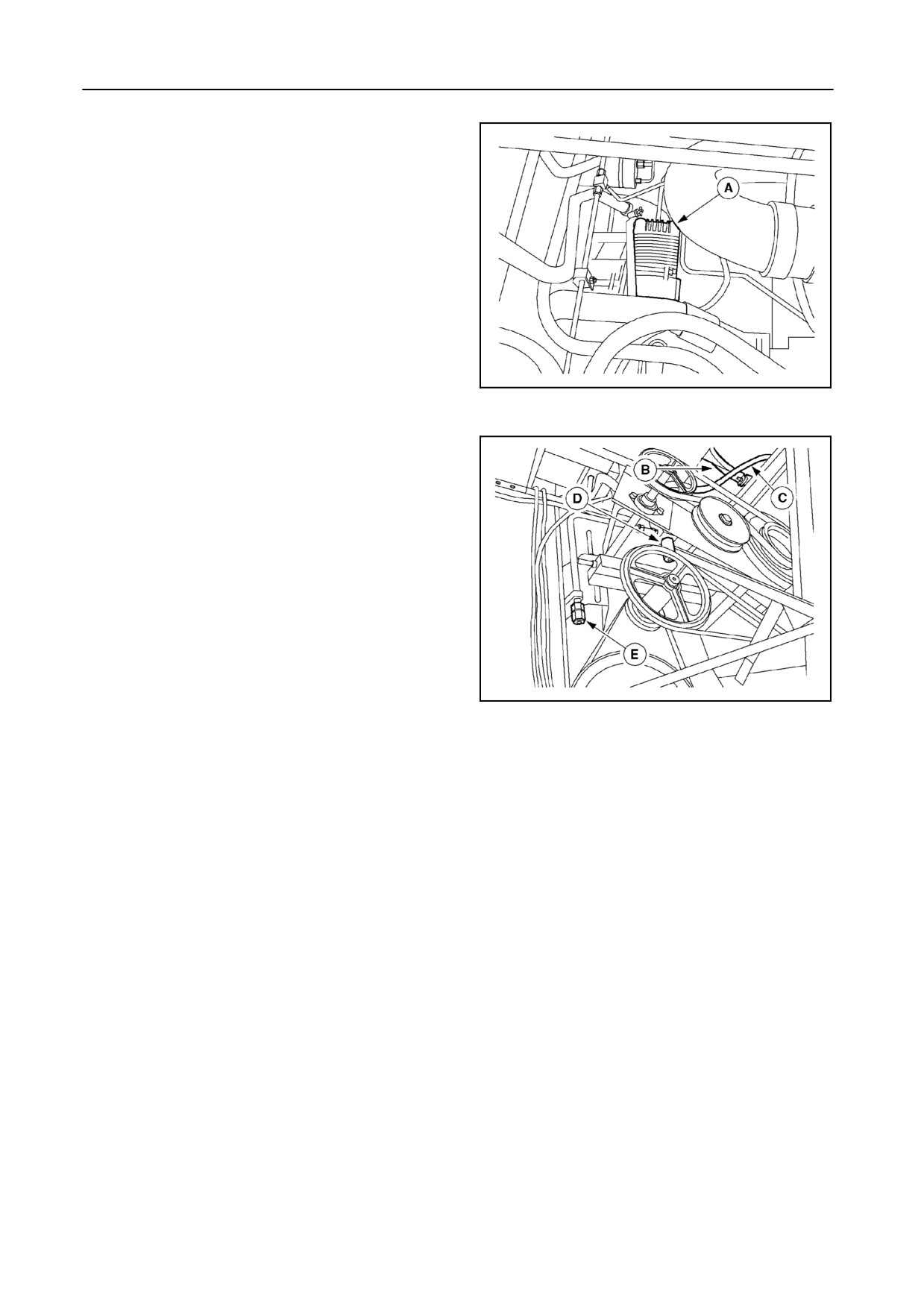
The air compressor A is installed near the engine and
needs no further maintenance.
43173
96
5-53
ADJUSTMENTS AND MAINTENANCE
Every 50 operating hours, drain the condensed water
from the air receiver B through cock C, and from the
water separator D.
A union E is installed to attach pneumatic service
tools and for cleaning purposes.
The inner thread of the union is 1/2 GAZ CYL.
43174
97
43175
98
Air reservoir specification
(according to European Directive 87/404/EEC)
S Trade mark: Wabco
S Type “60l”
S Maximum operating pressure: 10 bar
S Maximum operating temperature: +100°C
S Minimum operating temperature: --50°C
S Capacity:
60 litres
5-54
SECTION 5
HYDRAULIC SYSTEM
HYDRAULIC HOSE REPLACEMENT
S Flexible hose assemblies must not be
constructed from hoses which have
Hydraulic hoses are an important safety element in
been previously used as part of a
modern machinery. However, hose characteristics
hose assembly.
alter under pressure, thermal and UV light load over
S Do not weld to the piping.
the years. Therefore, most hoses now have a pro-
duction date printed on the metal clamp bushing
S If flexible hoses or piping are dam-
which allows to determine the age.
aged, replace them immediately.
Legislation in certain countries and good practice re-
S It is forbidden to modify an accumula-
quire that hydraulic hoses are replaced when they
tor by machining, welding or any
become 6 years old.
other means.
S Before removing accumulators for
servicing, the liquid pressure in the
CAUTION:
accumulator must be reduced to zero.
S Escaping fluid under pressure can
penetrate the skin causing serious in-
S Pressure check on accumulators
jury.
must be carried out by the method
Avoid the hazard by relieving pres-
recommended by the accumulator
sure before disconnecting hydraulic
manufacturer. Care must be taken not
orother lines. Tighten all connections
to exceed the maximum allowable
before applying pressure. Search for
pressure of the accumulator.
leaks with a piece of cardboard. Pro-
After any check of adjustment there
tect hands and body from high pres-
shall be no leakage of gas.
sure fluids.
IMPORTANT:
If an accident occurs, call for a doctor
The hydraulic valves on the left-hand side al-
immediately. Any fluid injected into
ways can be operated manually in case of
the skin must be surgically removed
electrical failure.
within a few hours. If not, gangrene
Push on the rubber caps of the solenoids to ac-
may result. Doctors unfamiliar with
tuate the hydraulic valve.
this type of injury should reference a
knowledgeable medical source.
Refer to Section 6 - TROUBLESHOOTING.
5-55
ADJUSTMENTS AND MAINTENANCE
ELECTRICAL SYSTEM
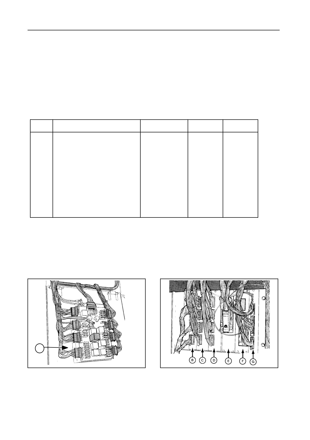
FUSES AND RELAYS -- Figures 99 and 100
All fuses and relays are situated in the box above the
right-hand traction wheel, except for the start relay
and the 12 - 24 V transformer (for these parts, refer to
the Service Parts Catalogue).
SUMMARY -- Figures 99 and 100
Item
Description
Connectors
Relays
Fuses
A
Power module
X31 - X39
K1 - K10
F1 - F37
B
CPU monitor
X44 - X46
--
--
(Central process unit)
C
Remote control printed circuit
X49 - X52
K32 - K48
--
D
Relay module
X53 - X56
K21 - K31
--
E
Header compensation
X57
--
--
control module
F
Lateral float and (ultrasonic)
X58 - X59A
--
--
autofloat module
G
Flex header reel speed printed
X59B - X65
--
--
circuit
2. When replacing a relay, make sure the
IMPORTANT:
new relay has the same ampere rating
1. When replacing a fuse, make sure the
and the same structure (visible on the
new fuse has the same ampere rating
relay housing).
as the fuse being replaced.
Always use genuine parts.
A
30231
51714
99
100
5-56
SECTION 5
51044
101
5-57
ADJUSTMENTS AND MAINTENANCE
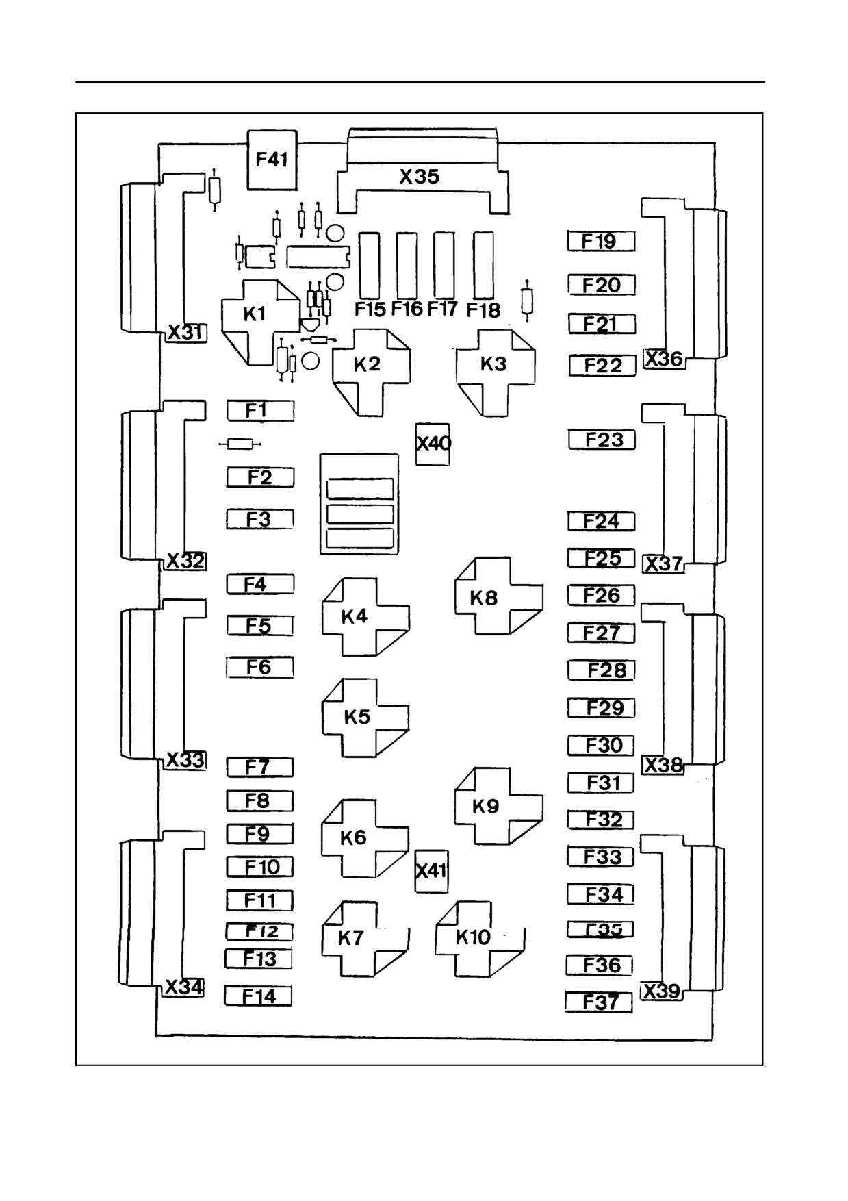
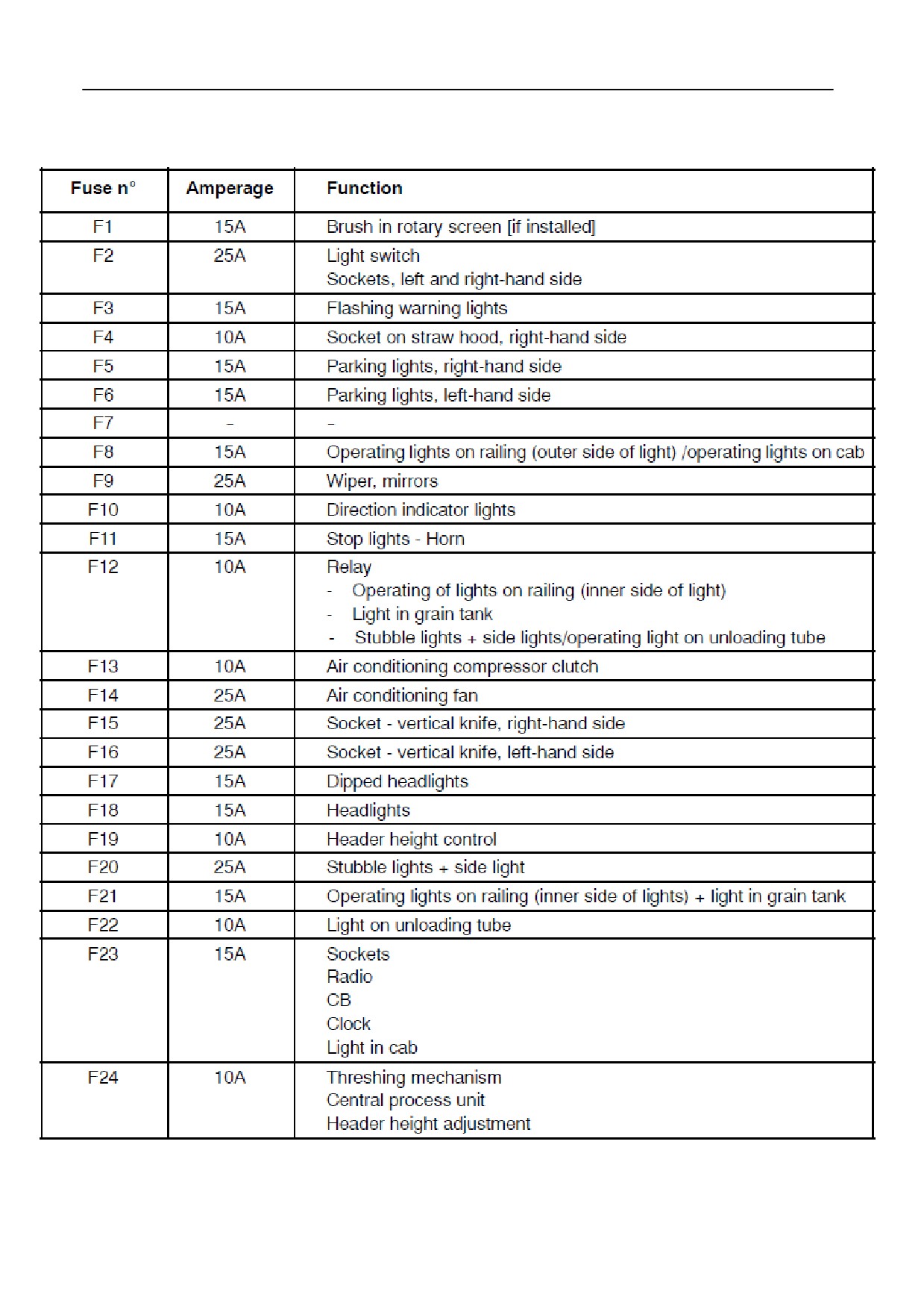
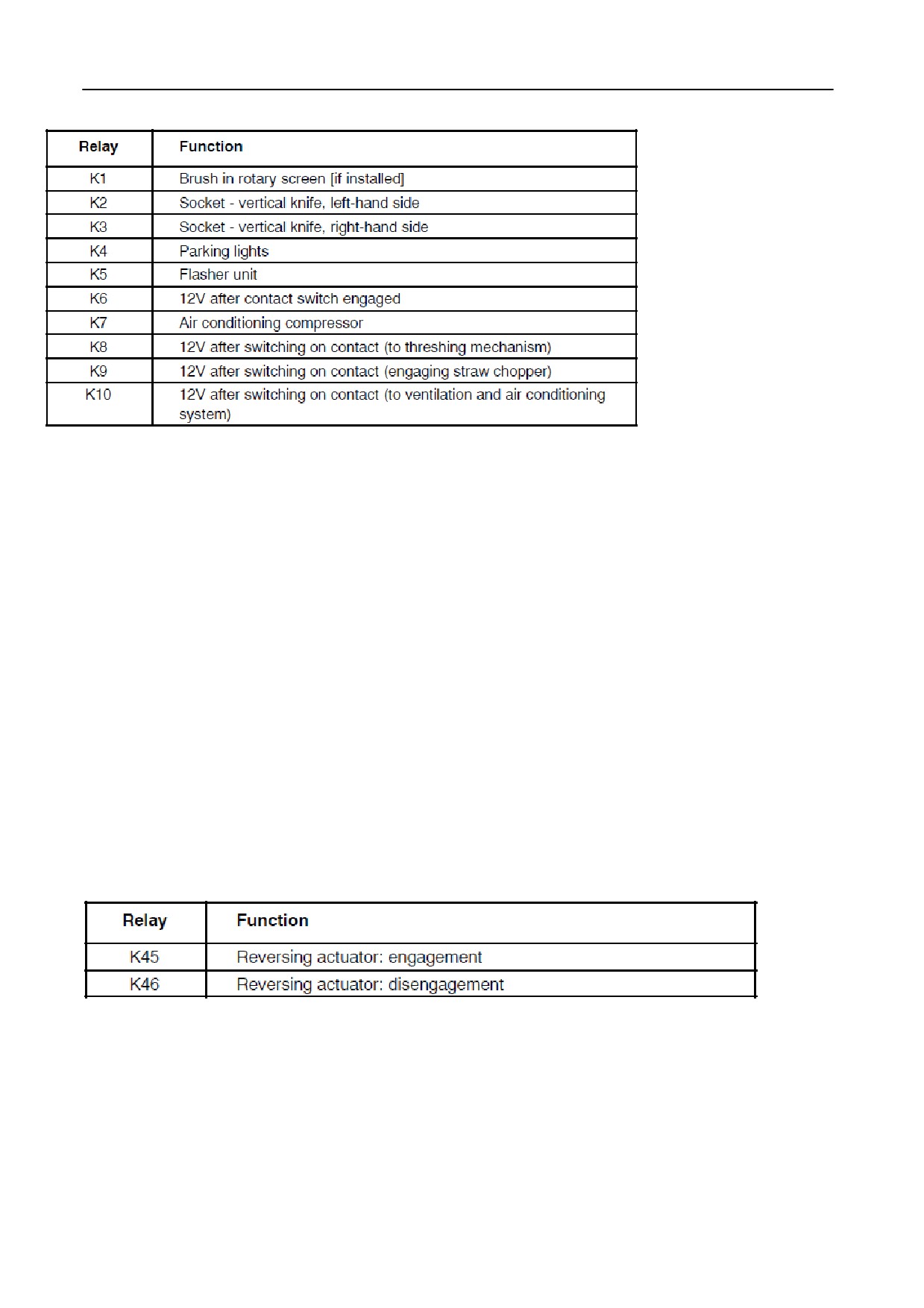
A. Power module -- Figures 99 and 101
5-58
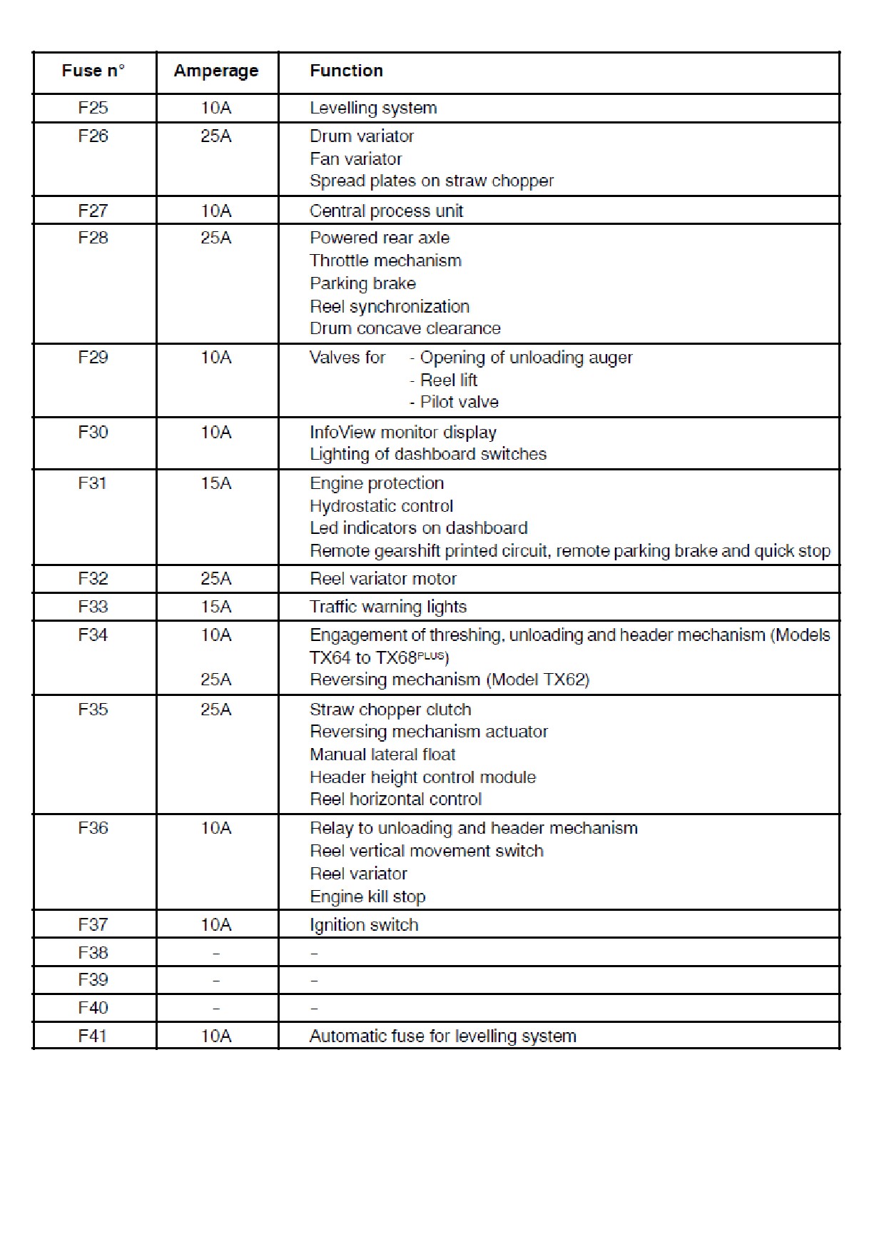
The same information can be found on the two decals inserted at the front of this Manual.
Adhere these decals to the electrical box access door, beside the power module.
5-59
ADJUSTMENTS AND MAINTENANCE
Three spare fuses FF are also stored in the power module.
B. Central process unit -- Figure 100
No fuses, no relays.
C. Remote controls printed circuit -- Figures 100 and 102
No fuses.
5-60