New Holland Tractor Workmaster 50 / Workmaster 60 / Workmaster 70 / Tier 4B (final). SERVICE MANUAL - page 24
Electrical systems - FAULT CODES
DTC 559-12-Fuel metering unit has an over-temperature error
Control Module : ECU
Context:
The Engine Control Unit (ECU) monitors the fuel metering unit Y-9000 signal circuit for an over temperature/current
condition. If the ECU A-9000 detects an over temperature/current condition in the fuel metering unit Y-9000 signal
circuit, this fault will occur.
Cause:
The ECU A-9000 has detected an over temperature/current condition in the fuel metering unit Y-9000 signal circuit.
Possible failure modes:
1. Faulty fuel metering unit Y-9000 wiring, short to a voltage source.
2. Faulty fuel metering unit Y-9000, internal failure.
3. Faulty ECU A-9000, software.
Solution:
1.
Verify fault is present and active.
Use the Electronic Service Tool (EST) to check the status of this fault.
A. If the fault is present and active, continue with Step 2.
B. If the fault is no longer present or in an inactive state, the fault may be intermittent and not currently active.
Continue with Step 5.
2.
Test the fuel metering unit Y-9000 internal resistance.
Disconnect the engine harness (EN) from the fuel metering unit Y-9000 at connector X-9007.
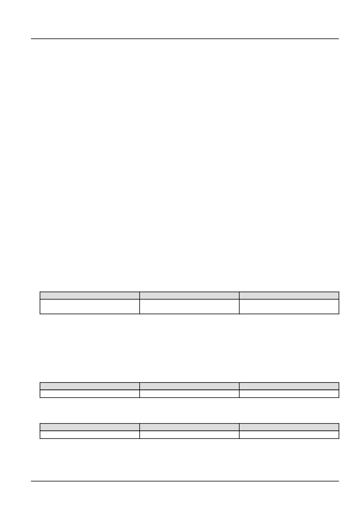
Use a multimeter to measure the resistance on the fuel metering unit Y-9000 pins :
From
To
Value
X-9007 pin 1
X-9007 pin 2
There should be between 2.6 - 3.2 Ω
at approximately 20.0 °C (68.0 °F).
A. If there is between 2.6 - 3.2 Ω, leave connector X-9007 disconnected and continue to Step 3.
B. If there is not between 2.6 - 3.2 Ω, the fuel metering unit Y-9000 has failed. Replace the fuel metering unit
Y-9000.
3.
Check the fuel metering unit Y-9000 low side driver wiring for a short to battery condition.
With the key in the OFF position, use a multimeter to perform the following voltage check on the engine harness
(EN) side :
From
To
Value
X-9007 pin 1
Chassis ground
There should be no voltage.
With the key in the ON position, use a multimeter to perform the following voltage check on the engine harness
(EN) side :
From
To
Value
X-9007 pin 1
Chassis ground
There should be no voltage.
A. If there is voltage, there is a short circuit to battery or switched battery in the fuel metering unit Y-9000 low
side driver circuit wiring. Use the appropriate service manual, if necessary, to locate and repair the shorted
conductor.
245
Electrical systems - FAULT CODES
B. If there is no voltage, leave connector X-9007 disconnected and continue to Step 4.
4. Check the fuel metering unit Y-9000 low side driver engine harness (EN) wiring for a short circuit condition.
Disconnect the engine harness (EN) from the ECU A-9000 at connector X-9001.
With the key in the OFF position, use a multimeter to perform the following continuity check from the engine har-
ness (EN) side :
From
To
Value
X-9001 pin A60
All pins in connector X-9001.
There should be no continuity.
A. If there is continuity, there is a short circuit condition in the fuel metering unit Y-9000 low side driver engine har-
ness (EN) wiring. Use the appropriate service manual, if necessary, to locate and repair the shorted conductor.
B. If there is no continuity, check the ECU A-9000 for the appropriate software and re-flash, if necessary.
5. Visually inspect the relevant harnesses and connectors for damage, bent or dislocated pins, corroded terminals,
or broken wires. Verify that the connectors are fully installed. Flex the harnesses involved to reveal intermittent
breaks or shorts in the wiring concerned. Operate the machine while you monitor the display.
A. If you find damage or the display indicates other than normal display readings, then repair the damage discov-
ered during the inspection or locate and repair the other than normal display condition and verify that the error
has been resolved.
B. If you do not find damage and the display indicates only normal readings, then erase the fault code and continue
operation.
Wiring harnesses - Electrical schematic sheet 03 - Engine sensors and fuel injection (engine schematics)
(55.100.DP-C.20.E.03)
246
Electrical systems - FAULT CODES
DTC 58C-03-Throttle valve actuator will not open to commanded
position
Control Module : ECU
NOTE: Once repaired, this fault may take up to up to 10 min of operation to reset.
Context:
The Engine Control Unit (ECU) A-9000 monitors the Throttle Valve Actuator (TVA) Z-9001. The TVA Z-9001 provides
the ECU A-9000 with a feedback using a position sensor. If the ECU A-9000 determines that there is a positive
deviation between the required and measured position, this fault will occur. If this fault is active, the ECU A-9000 will
command the TVA Z-9001 to open and close at a fast rate in order to attempt to “unblock “ the actuator. This fault is
not caused by a wiring failure. It is likely caused by an obstruction to the throttle valve flap or excessive carbon build
up on the throttle valve seat. For more information regarding TVA Z-9001 inspection, see Throttle Valve Actuator
(TVA) - Inspect (55.014).
Cause:
The ECU A-9000 has detected a positive deviation between the required and measured position of the TVA Z-9001.
The desired throttle valve position can not be reached.
Possible failure modes:
1. Faulty throttle valve actuator Z-9001, sticking or blocked.
2. Faulty throttle valve actuator Z-9001, internal failure.
3. Faulty ECU A-9000, software.
247
Electrical systems - FAULT CODES
DTC 58C-04-Throttle valve actuator will not close to commanded
position
Control Module : ECU
NOTE: Once repaired, this fault may take up to up to 10 min of operation to reset.
Context:
The Engine Control Unit (ECU) A-9000 monitors the Throttle Valve Actuator (TVA) Z-9001. The TVA Z-9001 provides
the ECU A-9000 with a feedback using a position sensor. If the ECU A-9000 determines that there is a negative
deviation between the required and measured position, this fault will occur. If this fault is active, the ECU A-9000 will
command the TVA Z-9001 to open and close at a fast rate in order to attempt to “unblock “ the actuator. This fault is
not caused by a wiring failure. It is likely caused by an obstruction to the throttle valve flap or excessive carbon build
up on the throttle valve seat.
Cause:
The ECU A-9000 has detected a negative deviation between the required and measured position of the TVA Z-9001.
The desired throttle valve position can not be reached. For more information regarding TVA Z-9001 inspection, see
Throttle Valve Actuator (TVA) - Inspect (55.014).
Possible failure modes:
1. Faulty throttle valve actuator Z-9001, sticking or blocked.
2. Faulty throttle valve actuator Z-9001, internal failure.
3. Faulty ECU A-9000, software.
248
Electrical systems - FAULT CODES
DTC 58D-03-Throttle valve actuator control circuit high side shorted
to battery
Control Module : ECU
Context:
The Engine Control Unit (ECU) A-9000 monitors the throttle valve actuator Z-9001 output 1 and output 2 h-bridge
circuits. If the ECU A-9000 detects a short to high source condition in the throttle valve actuator Z-9001 output 1
h-bridge circuit, this fault will occur.
Cause:
The ECU A-9000 has detected a short to high source condition in the throttle valve actuator Z-9001 output 1 h-bridge
circuit.
Possible failure modes:
1. Faulty throttle valve actuator Z-9001 wiring, short to a voltage source.
2. Faulty throttle valve actuator Z-9001, internal failure.
3. Faulty ECU A-9000, software.
Solution:
1.
Verify fault is present and active.
Use the Electronic Service Tool (EST) to check the status of this fault.
A. If the fault is present and active, continue with Step 2.
B. If the fault is no longer present or in an inactive state, the fault may be intermittent and not currently active.
Continue with Step 6.
2.
Check the throttle valve actuator Z-9001 output 1 h-bridge wiring for a short to battery condition.
Disconnect the engine harness (EN) from the throttle valve actuator Z-9001 at connector X-9011.
Disconnect the engine harness (EN) from the ECU A-9000 at connector X-9001.
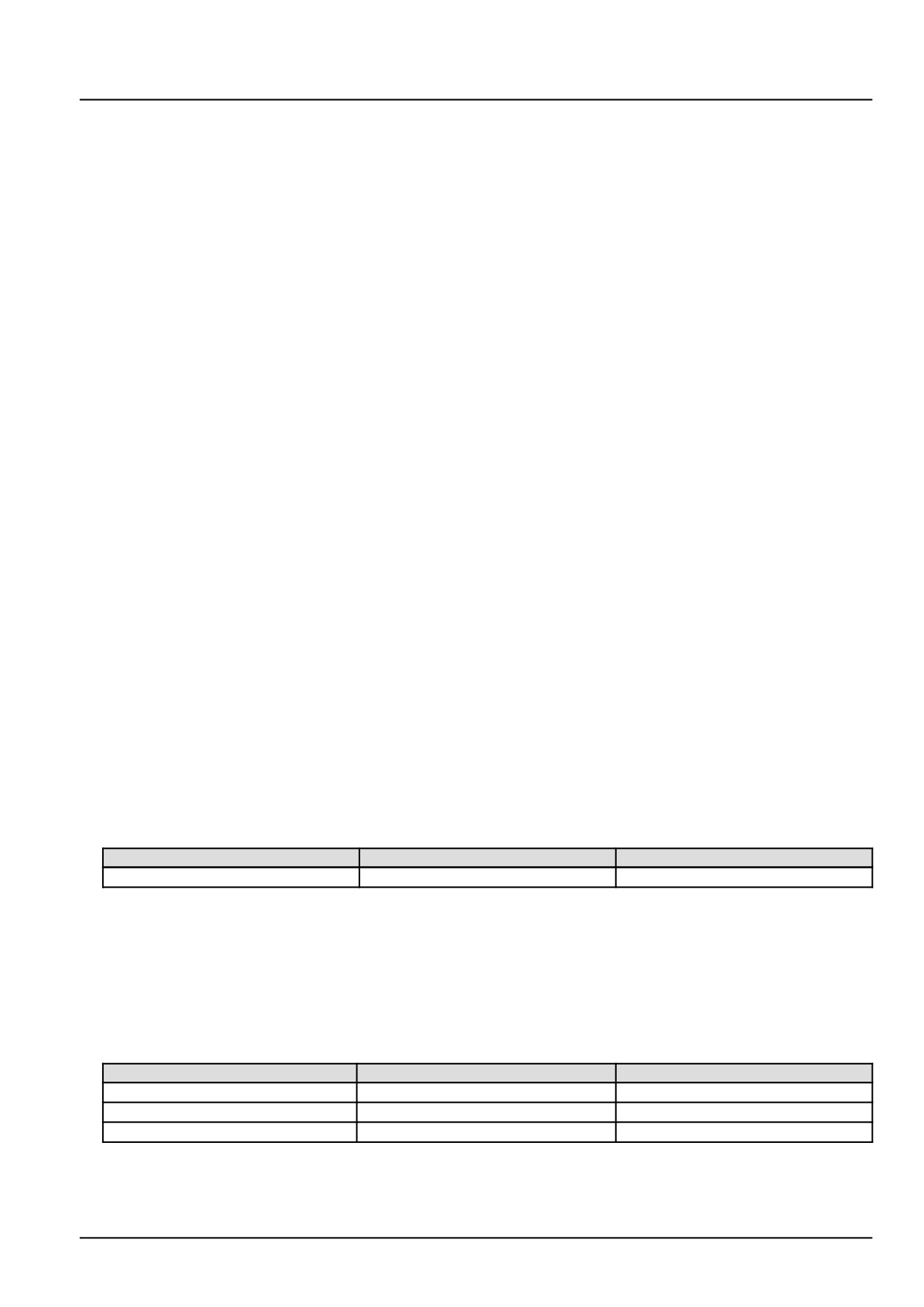
With the key in the ON position, use a multimeter to perform the following voltage check on the engine harness
(EN) side :
From
To
Value
X-9011 pin 6
Chassis ground
There should be no voltage.
A. If there is voltage, there is a short to battery in the throttle valve actuator Z-9001 output 1 h-bridge circuit.
Locate and repair the shorted conductor.
B. If there is no voltage, leave connectors X-9011 and X-9001 disconnected and continue to Step 3.
3.
Check the throttle valve actuator Z-9001 engine harness (EN) wiring for a short to high source condition.
With the key in the OFF position, use a multimeter to perform the following continuity check on the engine harness
(EN) side :
From
To
Value
X-9011 pin 6
X-9011 pin 1
There should be no continuity.
X-9011 pin 6
X-9011 pin 2
There should be no continuity.
X-9011 pin 6
Chassis ground
There should be no continuity.
A. If there is continuity, there is a short to high source in the throttle valve actuator Z-9001 output 1 h-bridge circuit.
Locate and repair the shorted conductor.
249
Electrical systems - FAULT CODES
B. If there is no continuity, leave connectors X-9011 and X-9001 disconnected and continue to Step 4.
4.
Check the throttle valve actuator Z-9001 engine harness (EN) wiring for a short to high source condition.
With the key in the OFF position, use a multimeter to perform the following continuity check on the engine harness
(EN) side :
From
To
Value
X-9001 pin A49
All pins in connector X-9001
There should be no continuity.
A. If there is continuity, there is a short to high source in the throttle valve actuator Z-9001 output 1 h-bridge circuit.
Locate and repair the shorted conductor.
B. If there is no continuity, leave connector X-9011 disconnected and continue to Step 5.
5.
Replace the throttle valve actuator Z-9001.
Use the Electronic Service Tool (EST) to check the status of this fault.
A. If the fault is no longer active, return the machine to service.
B. If the fault is still active, check the ECU A-9000 for the appropriate service manual and re-flash, if necessary.
6.
Visually inspect the relevant harnesses and connectors for damage, bent or dislocated pins, corroded terminals,
or broken wires. Verify that the connectors are fully installed. Flex the harnesses involved to reveal intermittent
breaks or shorts in the wiring concerned. Operate the machine while you monitor the display.
A. If you find damage or the display indicates other than normal display readings, then repair the damage discov-
ered during the inspection or locate and repair the other than normal display condition and verify that the error
has been resolved.
B. If you do not find damage and the display indicates only normal readings, then erase the fault code and continue
operation.
Wiring harnesses - Electrical schematic sheet 03 - Engine sensors and fuel injection (engine schematics)
(55.100.DP-C.20.E.03)
250
Electrical systems - FAULT CODES
DTC 58D-04-Throttle valve actuator control circuit high side shorted
to ground
Control Module : ECU
Context:
The Engine Control Unit (ECU) A-9000 monitors the throttle valve actuator Z-9001 output 1 and output 2 h-bridge
circuits. If the ECU A-9000 detects a short to ground condition in the throttle valve actuator Z-9001 output 1 h-bridge
circuit, this fault will occur.
Cause:
The ECU A-9000 has detected a short to ground condition in the throttle valve actuator Z-9001 output 1 h-bridge
circuit.
Possible failure modes:
1. Faulty throttle valve actuator Z-9001 wiring, short to ground condition.
2. Faulty throttle valve actuator Z-9001, internal failure.
3. Faulty ECU A-9000, software.
Solution:
1.
Verify fault is present and active.
Use the Electronic Service Tool (EST) to check the status of this fault.
A. If the fault is present and active, continue with Step 2.
B. If the fault is no longer present or in an inactive state, the fault may be intermittent and not currently active.
Continue with Step 5.
2.
Check the throttle valve actuator Z-9001 output 1 h-bridge engine harness (EN) wiring for a short to ground con-
dition.
Disconnect the engine harness (EN) from the throttle valve actuator Z-9001 at connector X-9011.
Disconnect the engine harness (EN) from the ECU A-9000 at connector X-9001.
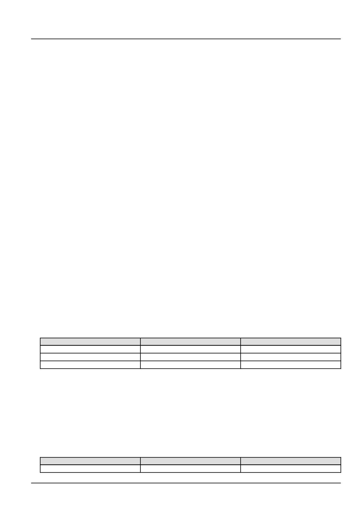
With the key in the OFF position, use a multimeter to perform the following continuity check on the engine harness
(EN) side :
From
To
Value
X-9011 pin 6
Chassis ground
There should be no continuity.
X-9011 pin 6
X-9011 pin 2
There should be no continuity.
X-9011 pin 6
X-9011 pin 3
There should be no continuity.
A. If there is continuity, there is a short circuit in the throttle valve actuator Z-9001 output 1 h-bridge circuit. Locate
and repair the shorted conductor.
B. If there is no continuity, leave connector X-9011 disconnected and continue to Step 3.
3.
Check the throttle valve actuator Z-9001 output 1 h-bridge engine harness (EN) wiring for a short to ground con-
dition.
Disconnect the engine harness (EN) from the ECU A-9000 at connector X-9001.
With the key in the OFF position, use a multimeter to perform the following continuity check on the vehicle harness
(VE) side :
From
To
Value
X-9001 pin A49
All pins in connector X-9001
There should be no continuity.
251
Electrical systems - FAULT CODES
A. If there is continuity, there is a short circuit in the throttle valve actuator Z-9001 output 1 h-bridge circuit. Locate
and repair the shorted conductor.
B. If there is no continuity, leave the connector X-9011 disconnected and continue to Step 4.
4. Replace the throttle valve actuator Z-9001.
Use the Electronic Service Tool (EST) to check the status of this fault.
A. If the fault is no longer active, return the machine to service.
B. If the fault is still active, check the ECU A-9000 for the appropriate service manual and re-flash, if necessary.
5. Visually inspect the relevant harnesses and connectors for damage, bent or dislocated pins, corroded terminals,
or broken wires. Verify that the connectors are fully installed. Flex the harnesses involved to reveal intermittent
breaks or shorts in the wiring concerned. Operate the machine while you monitor the display.
A. If you find damage or the display indicates other than normal display readings, then repair the damage discov-
ered during the inspection or locate and repair the other than normal display condition and verify that the error
has been resolved.
B. If you do not find damage and the display indicates only normal readings, then erase the fault code and continue
operation.
Wiring harnesses - Electrical schematic sheet 03 - Engine sensors and fuel injection (engine schematics)
(55.100.DP-C.20.E.03)
252
Electrical systems - FAULT CODES
DTC 5D2-03-ECU internal failure - EEPROM memory failure
Control Module : ECU
Context:
The Engine Control Unit (ECU) A-9000 calculates the correction values from the EEPROM. If the ECU A-9000 detects
an error n the EEPROM block, this fault will occur.
Solution:
1. Check the ECU A-9000 for the appropriate software and re-flash, if necessary.
A. If the fault has been resolved, return the machine to service.
B. If the fault has not been resolved, escalate an ASIST concern.
253
Electrical systems - FAULT CODES
DTC 5D4-02-ECU internal failure - WDA is not working correctly
Control Module : ECU
Context:
The Engine Control Unit (ECU) A-9000 performs “shut-off paths” which deactivate all power stages relevant to fuel in-
jection if certain ECU A-9000 errors are detected. If an implausible response in the power-stage feedback is detected
during this test, this fault will occur.
Solution:
1. Check the ECU A-9000 for the appropriate software and re-flash, if necessary.
A. If the fault has been resolved, return the machine to service.
B. If the fault has not been resolved, escalate an ASIST concern.
254
Electrical systems - FAULT CODES
DTC 5D4-03-ECU internal failure - Alarm task period error
Control Module : ECU
Context:
The Engine Control Unit (ECU) A-9000 performs “shut-off paths” which deactivate all power stages relevant to fuel
injection if certain ECU A-9000 errors are detected. If an alarm task can not be set or reset after having detected a
time-out error during this test, this fault will occur.
Solution:
1. Check the ECU A-9000 for the appropriate software and re-flash, if necessary.
A. If the fault has been resolved, return the machine to service.
B. If the fault has not been resolved, escalate an ASIST concern.
255
Electrical systems - FAULT CODES
DTC 5D4-04-ECU internal failure - Positive test failed
Control Module : ECU
Context:
The Engine Control Unit (ECU) A-9000 performs “shut-off paths” which deactivate all power stages relevant to fuel
injection if certain ECU A-9000 errors are detected. If the ECU A-9000 determines that the test has failed, this fault
will occur.
Solution:
1. Check the ECU A-9000 for the appropriate software and re-flash, if necessary.
A. If the fault has been resolved, return the machine to service.
B. If the fault has not been resolved, escalate an ASIST concern.
256
Electrical systems - FAULT CODES
DTC 5D4-12-ECU internal failure - Timeout in the shut off path test
error
Control Module : ECU
Context:
The Engine Control Unit (ECU) A-9000 performs “shut-off paths” which deactivate all power stages relevant to fuel
injection if certain ECU A-9000 errors are detected. If a time-out in the power-stage feedback is detected during this
test, this fault will occur.
Solution:
1. Check the ECU A-9000 for the appropriate software and re-flash, if necessary.
A. If the fault has been resolved, return the machine to service.
B. If the fault has not been resolved, escalate an ASIST concern.
257
Electrical systems - FAULT CODES
DTC 5E3-03-ECU internal failure - Torque request due to fuel
pressure exceeds maximum torque limit
Control Module : ECU
Context:
The Engine Control Unit (ECU) A-9000 monitors “lead torque”, which is the input torque request that is calculated for
determining fuel pressure. If the ECU A-9000 determines that “lead torque” is less than the limited maximal torque,
this fault will occur.
Solution:
1. Check the ECU A-9000 for the appropriate software and re-flash, if necessary.
A. If the fault has been resolved, return the machine to service.
B. If the fault has not been resolved, escalate an ASIST concern.
258
Electrical systems - FAULT CODES
DTC 5E3-04-ECU internal failure - Torque request due to air control
exceeds maximum torque limit
Control Module : ECU
Context:
The Engine Control Unit (ECU) A-9000 monitors “lead torque”, which is the input torque request that is calculated for
determining fuel pressure. If the ECU A-9000 determines that “lead torque” is less than the limited maximal torque,
this fault will occur.
Solution:
1. Check the ECU A-9000 for the appropriate software and re-flash, if necessary.
A. If the fault has been resolved, return the machine to service.
B. If the fault has not been resolved, escalate an ASIST concern.
259
Electrical systems - FAULT CODES
DTC 5E3-12-ECU internal failure - Torque request exceeds
maximum torque limit
Control Module : ECU
Context:
The Engine Control Unit (ECU) A-9000 calculates and monitors “inner torque”, torque produced by the engine. The
ECU A-9000 compares “inner torque” to allowed “inner torque”. If the ECU A-9000 determines that “Inner torque” is
greater than allowed “inner torque”, this fault will occur.
Solution:
1. Check the ECU A-9000 for the appropriate software and re-flash, if necessary.
A. If the fault has been resolved, return the machine to service.
B. If the fault has not been resolved, escalate an ASIST concern.
260
Electrical systems - FAULT CODES
DTC 601-02-Lambda sensor nernst cell open circuit
Control Module : ECU
NOTE: If the Lambda sensor B-9123 is replaced, it is necessary to perform the Replacement of the Lambda Sensor
- Reset ECU Data with the Electronic Service Tool (EST) before you return the machine to service. See Lambda
sensor - Configure - Reset ECU data (Lambda sensor) (55.989), if necessary.
Context:
For information regarding the functional operation of the Lambda sensor B-9123 see Lambda sensor - Overview
(55.989). The Engine Control Unit (ECU) A-9000 has determined that the Lambda sensor B-9123 nernst signal is not
present. The Lambda sensor B-9123 is the primary measurement device for ECU A-9000 fuel control, to determine
if the engine is too rich or too lean. For more information regarding the technical specifications of the lambda sensor
B-9123, see Lambda sensor - Technical Data (55.989).
Cause:
The ECU A-9000 is sensing an open circuit condition in the Lambda sensor B-9123 nernst signal circuit.
Possible failure modes:
1. Faulty Lambda sensor B-9123 circuit wiring, open circuit.
2. Faulty Lambda sensor B-9123, failed internally.
3. Faulty ECU A-9000, software.
Solution:
1.
Verify that the fault present and active.
Use the Electronic Service Tool (EST) to check the status of this fault.
A. If the fault is present and active, continue with Step 2.
B. If the fault is no longer present or in an inactive state, the fault may be intermittent and not currently active.
Continue with Step 4.
2.
Check the Lambda sensor B-9123 nernst signal circuit wiring for an open circuit condition.
Disconnect the vehicle harness (VE) from the Lambda sensor B-9123 at connector X-9123.
Disconnect the vehicle harness (VE) from the ECU A-9000 at connector X-9102.
With the key in the OFF position, use a multimeter to perform the following continuity check for an open circuit on
the vehicle harness (VE) side :
From
To
Value
X-9123 pin 6
X-9102 pin K63
There should be continuity.
A. If there is no continuity, there is an open circuit condition in the vehicle harness (VE) between connector X-9123
pin 6 and X-9102 pin K63.Use the appropriate vehicle service manual, if necessary, to locate and repair the
broken conductor.
B. If there is continuity, leave connector X-9123 disconnected and continue to Step 3.
3.
Replace the Lambda sensor B-9123.
Use the EST, see Lambda sensor - Configure - Reset ECU data (Lambda sensor) (55.989) if necessary, to
perform the Replacement of the Lambda Sensor - Reset ECU Data.
Use EST to check to see that this fault has been resolved.
A. If the fault has been resolved, return the machine to service.
B. If this fault has not been resolved, check the ECU A-9000 for the appropriate software and re-flash, if necessary.
261
Electrical systems - FAULT CODES
4. Visually inspect the relevant harnesses and connectors for damage, bent or dislocated pins, corroded terminals,
or broken wires.
Verify that the connectors are fully installed.
Flex the harnesses involved to reveal intermittent breaks or shorts in the wiring concerned.
Operate the machine while you monitor the display.
A. If you find damage or the display indicates other than normal display readings, then repair the damage discov-
ered during the inspection or locate and repair the other than normal display condition and verify that the error
has been resolved.
B. If you do not find damage and the display indicates only normal readings, then erase the fault code and continue
operation.
Wiring harnesses - Electrical schematic sheet 02 - Engine Control Unit (ECU) power and after treatment
system (engine schematics) (55.100.DP-C.20.E.02)
262
Electrical systems - FAULT CODES
DTC 602-02-Lambda sensor pump current open circuit
Control Module : ECU
NOTE: If the Lambda sensor B-9123 is replaced, it is necessary to perform the Replacement of the Lambda Sensor
- Reset ECU Data with the Electronic Service Tool (EST) before you return the machine to service. See Lambda
sensor - Configure - Reset ECU data (Lambda sensor) (55.989), if necessary.
Context:
The Engine Control Unit (ECU) A-9000 has determined that the Lambda sensor B-9123 pump current is not present.
The Lambda sensor B-9123 is the primary measurement device for ECU A-9000 fuel control, to determine if the
engine is too rich or too lean. For information regarding the functional operation of the Lambda sensor B-9123 see
Lambda sensor - Overview (55.989). For more information regarding the technical specifications of the lambda
sensor B-9123, see Lambda sensor - Technical Data (55.989).
Cause:
The ECU A-9000 is sensing an open circuit condition in the Lambda sensor B-9123 pump current control circuit.
Possible failure modes:
1. Faulty Lambda sensor B-9123 pump current control circuit wiring, open circuit.
2. Faulty Lambda sensor B-9123, failed internally.
3. Faulty ECU A-9000, software.
Solution:
1.
Verify that the fault present and active.
Use the Electronic Service Tool (EST) to check the status of this fault.
A. If the fault is present and active, continue with Step 2.
B. If the fault is no longer present or in an inactive state, the fault may be intermittent and not currently active.
Continue with Step 4.
2.
Check the Lambda sensor B-9123 pump current control circuit wiring for an open circuit condition.
Disconnect the vehicle harness (VE) from the Lambda sensor B-9123 at connector X-9123.
Disconnect the vehicle harness (VE) from the ECU A-9000 at connector X-9102.
With the key in the OFF position, use a multimeter to perform the following continuity check for an open circuit on
the vehicle harness (VE) side :
From
To
Result
X-9123 pin 1
X-9102 pin K64
There should be continuity.
A. If there is no continuity, there is an open circuit condition in the vehicle harness (VE) between connector X-9123
pin 1 and connector X-9102 pin K64. Use the appropriate vehicle service manual, if necessary, to locate and
repair the broken conductor.
B. If there is continuity, leave connector X-9123 disconnected and continue to Step 3.
3.
Replace the Lambda sensor B-9123.
Use the EST, see Lambda sensor - Configure - Reset ECU data (Lambda sensor) (55.989) if necessary, to
perform the Replacement of the Lambda Sensor - Reset ECU Data.
Use EST to check to see that this fault has been resolved.
A. If the fault has been resolved, return the machine to service.
B. If this fault has not been resolved, check the ECU A-9000 for the appropriate software and re-flash, if necessary.
263
Electrical systems - FAULT CODES
4. Visually inspect the relevant harnesses and connectors for damage, bent or dislocated pins, corroded terminals,
or broken wires.
Verify that the connectors are fully installed.
Flex the harnesses involved to reveal intermittent breaks or shorts in the wiring concerned.
Operate the machine while you monitor the display.
A. If you find damage or the display indicates other than normal display readings, then repair the damage discov-
ered during the inspection or locate and repair the other than normal display condition and verify that the error
has been resolved.
B. If you do not find damage and the display indicates only normal readings, then erase the fault code and continue
operation.
Wiring harnesses - Electrical schematic sheet 02 - Engine Control Unit (ECU) power and after treatment
system (engine schematics) (55.100.DP-C.20.E.02)
264
Electrical systems - FAULT CODES
DTC 605-03-Lambda sensor O2 value above maximum threshold
Control Module : ECU
NOTE: If the Lambda sensor B-9123 is replaced, it is necessary to perform the Replacement of the Lambda Sensor
- Reset ECU Data with the Electronic Service Tool (EST) before you return the machine to service. See Lambda
sensor - Configure - Reset ECU data (Lambda sensor) (55.989), if necessary.
Context:
The Engine Control Unit (ECU) A-9000 has detected a fault associated with the oxygen sensor. This fault is a result of
an open circuit condition in the factory installed trim resistor circuit. For information regarding the functional operation
of the Lambda sensor B-9123 see Lambda sensor - Overview (55.989). For more information regarding the technical
specifications of the lambda sensor B-9123, see Lambda sensor - Technical Data (55.989).
Cause:
The ECU A-9000 is sensing an open circuit condition in the Lambda sensor B-9123 trim resistor circuit.
Possible failure modes:
1. Faulty Lambda sensor B-9123 circuit wiring, open circuit.
2. Faulty Lambda sensor B-9123, failed internally.
3. Faulty ECU A-9000, software.
Solution:
1.
Verify that the fault present and active.
Use the Electronic Service Tool (EST) to check the status of this fault.
A. If the fault is present and active, continue with Step 2.
B. If the fault is no longer present or in an inactive state, the fault may be intermittent and not currently active.
Continue with Step 4.
2.
Check the Lambda sensor B-9123 trim resistor circuit wiring for an open or short circuit condition.
Disconnect the vehicle harness (VE) from the Lambda sensor B-9123 at connector X-9123
Carefully disconnect the vehicle harness (VE) from the ECU A-9000 at connector X-9102.
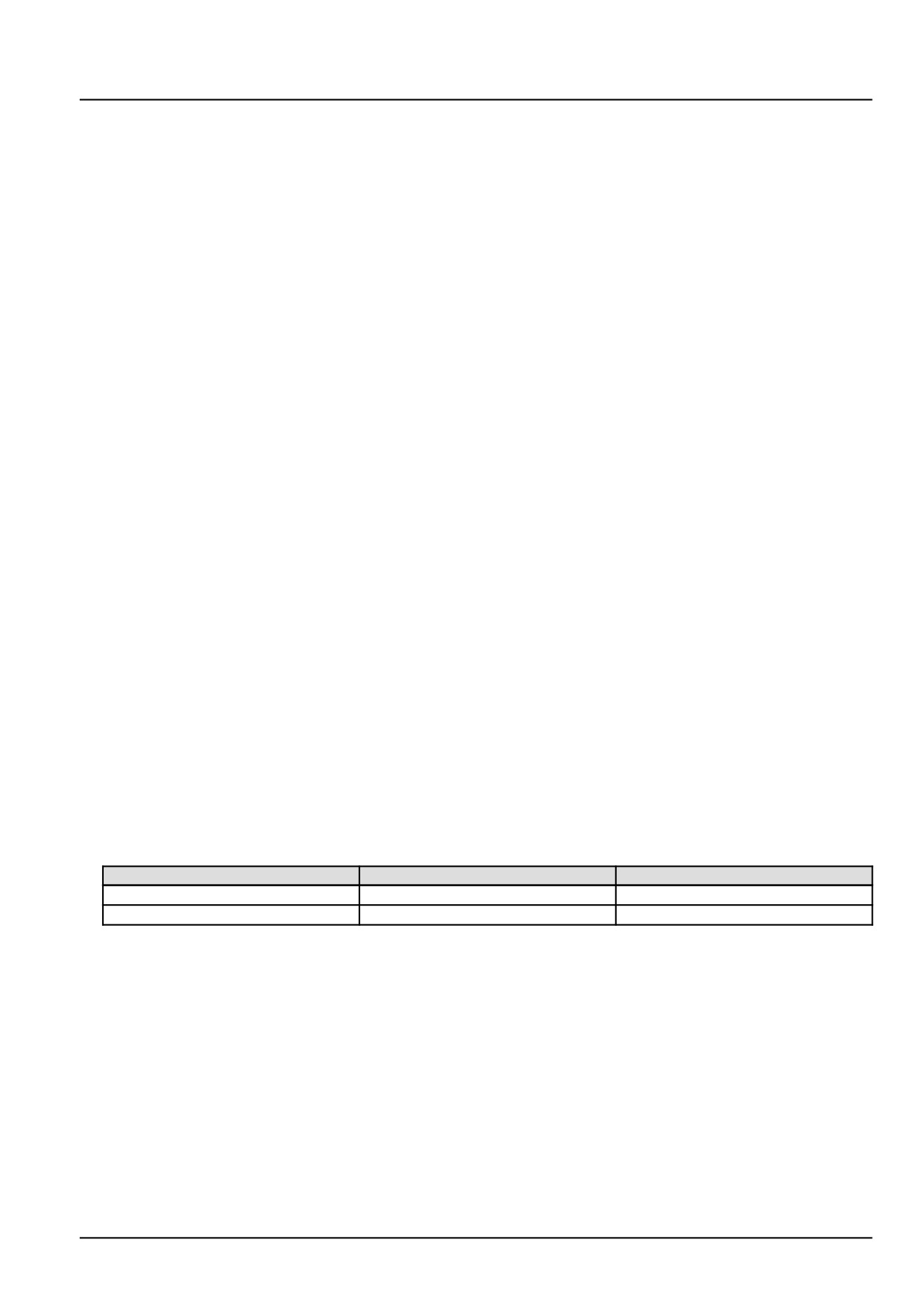
With the key in the OFF position, use a multimeter to check for continuity on the vehicle harness (VE) side :
From
To
Value
X-9123 pin 5
X-9102 pin K86
There should be continuity.
X-9102 pin K86
All other pins on connector X-9102
There should be no continuity.
A. If there is no continuity, there is an open circuit condition in the Lambda sensor B-9123 trim resistor circuit wiring
in the vehicle harness (VE). Use the appropriate vehicle service manual, if necessary, to locate and repair the
broken conductor.
B. If there is continuity, continue with Step 3.
3.
Replace the Lambda sensor B-9123.
Use EST to check to see that this fault has been resolved.
A. If the fault has been resolved, return the machine to service.
B. If this fault has not been resolved, check the ECU A-9000 for the appropriate software and re-flash, if necessary.
4.
Visually inspect the relevant harnesses and connectors for damage, bent or dislocated pins, corroded terminals,
or broken wires.
265
Electrical systems - FAULT CODES
Verify that the connectors are fully installed.
Flex the harnesses involved to reveal intermittent breaks or shorts in the wiring concerned.
Operate the machine while you monitor the display.
A. If you find damage or the display indicates other than normal display readings, then repair the damage discov-
ered during the inspection or locate and repair the other than normal display condition and verify that the error
has been resolved.
B. If you do not find damage and the display indicates only normal readings, then erase the fault code and continue
operation.
Wiring harnesses - Electrical schematic sheet 02 - Engine Control Unit (ECU) power and after treatment
system (engine schematics) (55.100.DP-C.20.E.02)
266
Electrical systems - FAULT CODES
DTC 606-02-Lambda sensor virtual ground open circuit
Control Module : ECU
NOTE: If the Lambda sensor B-9123 is replaced, it is necessary to perform the Replacement of the Lambda Sensor
- Reset ECU Data with the Electronic Service Tool (EST) before you return the machine to service. See Lambda
sensor - Configure - Reset ECU data (Lambda sensor) (55.989), if necessary.
Context:
For information regarding the functional operation of the Lambda sensor B-9123 see Lambda sensor - Overview
(55.989). The Engine Control Unit (ECU) A-9000 has determined that the Lambda sensor B-9123 virtual ground circuit
is open. The Lambda sensor B-9123 is the primary measurement device for ECU A-9000 fuel control, to determine
if the engine is too rich or too lean. For more information regarding the technical specifications of the lambda sensor
B-9123, see Lambda sensor - Technical Data (55.989).
Cause:
The ECU A-9000 is sensing an open circuit condition in the Lambda sensor B-9123 virtual ground circuit.
Possible failure modes:
1. Faulty Lambda sensor B-9123 virtual ground circuit wiring, open circuit.
2. Faulty Lambda sensor B-9123, failed internally.
3. Faulty ECU A-9000, software.
Solution:
1.
Verify that the fault present and active.
Use the Electronic Service Tool (EST) to check the status of this fault.
A. If the fault is present and active, continue with Step 2.
B. If the fault is no longer present or in an inactive state, the fault may be intermittent and not currently active.
Continue with Step 4.
2.
Check the Lambda sensor B-9123 virtual ground circuit wiring for an open circuit condition.
Disconnect the vehicle harness (VE) from the Lambda sensor B-9123 at connector X-9123.
Disconnect the vehicle harness (VE) from the ECU A-9000 at connector X-9102.
With the key in the OFF position, use a multimeter to perform the following continuity check for an open circuit on
the vehicle harness (VE) side :
From
To
Value
X-9123 pin 2
X-9102 pin K85
There should be continuity.
A. If there is no continuity, there is an open circuit condition in the vehicle harness (VE) between connector X-9123
pin 2 and X-9102 pin K85.Use the appropriate vehicle service manual, if necessary, to locate and repair the
broken conductor.
B. If there is continuity, continue with Step 3.
3.
Replace the Lambda sensor B-9123.
Use EST to check to see that this fault has been resolved.
A. If the fault has been resolved, use the EST, see Lambda sensor - Configure - Reset ECU data (Lambda
sensor) (55.989) if necessary, to perform the Replacement of the Lambda Sensor - Reset ECU Data. Then
return the machine to service.
B. If this fault has not been resolved, check the ECU A-9000 for the appropriate software and re-flash, if necessary.
267
Electrical systems - FAULT CODES
4. Visually inspect the relevant harnesses and connectors for damage, bent or dislocated pins, corroded terminals,
or broken wires.
Verify that the connectors are fully installed.
Flex the harnesses involved to reveal intermittent breaks or shorts in the wiring concerned.
Operate the machine while you monitor the display.
A. If you find damage or the display indicates other than normal display readings, then repair the damage discov-
ered during the inspection or locate and repair the other than normal display condition and verify that the error
has been resolved.
B. If you do not find damage and the display indicates only normal readings, then erase the fault code and continue
operation.
Wiring harnesses - Electrical schematic sheet 02 - Engine Control Unit (ECU) power and after treatment
system (engine schematics) (55.100.DP-C.20.E.02)
268
Electrical systems - FAULT CODES
DTC 607-03-Lambda sensor O2 calibrator too high error
Control Module : ECU
NOTE: If the Lambda sensor B-9123 is replaced, it is necessary to perform the Replacement of the Lambda Sensor
- Reset ECU Data with the Electronic Service Tool (EST) before you return the machine to service. See Lambda
sensor - Configure - Reset ECU data (Lambda sensor) (55.989), if necessary.
Context:
The Engine Control Unit (ECU) A-9000 performs an electrical zero-offset calibration every 10 min of engine operation
on the Lambda sensor B-9123 as long as the engine has been running for longer than 10 s after start, after-treatment
regeneration is not active, the engine is in operating range one (speed between 300 - 1200 RPM and load between
2.00 - 11.00 mg per stroke), and the calibration is not inhibited due to a failure. The measured oxygen signal during
calibration should be between - 0.200 - 0.200 V. If the oxygen signal, during this calibration, is out of range, higher
than 0.200 V, this fault will occur. For more information regarding fuel system troubleshooting, see Fuel injection
system - Troubleshooting (10.218). For information regarding the functional operation of the Lambda sensor B-9123
see Lambda sensor - Overview (55.989). For more information regarding the technical specifications of the lambda
sensor B-9123, see Lambda sensor - Technical Data (55.989).
Cause:
The Lambda sensor B-9123 oxygen level signal, during calibration, to the ECU A-9000 is greater than 0.200 V.
Possible failure modes:
1. Faulty injector, leaking.
2. Faulty Exhaust Gas Recirculation (EGR) Z-9000 valve, stuck closed. (If applicable)
3. Faulty Lambda sensor B-9123, contaminated.
4. Faulty ECU A-9000, software.
269
Electrical systems - FAULT CODES
DTC 607-04-Lambda sensor O2 calibrator too low error
Control Module : ECU
NOTE: If the Lambda sensor B-9123 is replaced, it is necessary to perform the Replacement of the Lambda Sensor
- Reset ECU Data with the Electronic Service Tool (EST) before you return the machine to service. See Lambda
sensor - Configure - Reset ECU data (Lambda sensor) (55.989), if necessary.
Context:
The Engine Control Unit (ECU) A-9000 performs an electrical zero-offset calibration every 10 min of engine operation
on the Lambda sensor B-9123 as long as the engine has been running for longer than 10 s after start, after-treatment
regeneration is not active, the engine is in operating range one (speed between 300 - 1200 RPM and load between
2.00 - 11.00 mg per stroke), and the calibration is not inhibited due to a failure. The measured oxygen signal during
calibration should be between - 0.200 - 0.200 V. If the oxygen signal, during this calibration, is out of range, less than -
0.200 V, this fault will occur. For more information regarding fuel system troubleshooting, see Fuel injection system
- Troubleshooting (10.218). For information regarding the functional operation of the Lambda sensor B-9123 see
Lambda sensor - Overview (55.989). For more information regarding the technical specifications of the lambda
sensor B-9123, see Lambda sensor - Technical Data (55.989).
Cause:
The Lambda sensor B-9123 oxygen level signal, during calibration, to the ECU A-9000 is less than - 0.200 V.
Possible failure modes:
1. Faulty fuel back-flow, excessive.
2. Faulty Exhaust Gas Recirculation (EGR) Z-9000 valve, stuck open. (If applicable)
3. Faulty Lambda sensor B-9123, contaminated.
4. Faulty ECU A-9000, software.
270
Electrical systems - FAULT CODES
DTC 609-02-ECU internal failure - SPI chip error configuration
Control Module : ECU
Context:
The SPI chip, which is internal to the ECU A-9000, controls the Lambda sensor B-9123 device for the measuring or
the calibrating of the inner resistance for temperature evaluation, switches on and off the pump current to measure
O2 content and monitors the hardware related to the open load and short circuit monitoring devices. The requests for
these listed actions are made by software and result in a configuration of the initialization register, which is hardware
controlled. The same configuration is calculated by software. If both configurations are not identical, the SPI is not
plausible and this fault will occur. For information regarding the functional operation of the Lambda sensor B-9123
see Lambda sensor - Overview (55.989). For more information regarding the technical specifications of the lambda
sensor B-9123, see Lambda sensor - Technical Data (55.989).
Solution:
1. Check the ECU A-9000 for the appropriate software and re-flash, if necessary.
A. If the fault has been resolved, return the machine to service.
B. If the fault has not been resolved, escalate an ASIST concern.
271
Electrical systems - FAULT CODES
DTC 60A-04-Lambda sensor heater battery voltage too low
Control Module : ECU
NOTE: If the Lambda sensor B-9123 is replaced, it is necessary to perform the Replacement of the Lambda Sensor
- Reset ECU Data with the Electronic Service Tool (EST) before you return the machine to service. See Lambda
sensor - Configure - Reset ECU data (Lambda sensor) (55.989), if necessary.
Context:
The SPI chip, which is internal to the ECU A-9000, controls the Lambda sensor B-9123 device for the measuring or
the calibrating of the inner resistance for temperature evaluation, switches on and off the pump current to measure O2
content and monitors the hardware related to the open load and short circuit monitoring devices. If the SPI chip senses
a very low battery voltage, less than 9.0 V this fault will occur. For information regarding the functional operation of
the Lambda sensor B-9123 see Lambda sensor - Overview (55.989). For more information regarding the technical
specifications of the lambda sensor B-9123, see Lambda sensor - Technical Data (55.989).
Cause:
The ECU has sensed low voltage in the lambda sensor circuit.
Possible failure modes:
1. Low battery voltage.
2. Faulty Lambda sensor B-9123 supply circuit wiring.
3. Faulty Lambda sensor B-9123, failed internally.
4. Faulty ECU A-9000, software.
Solution:
1.
Verify that the fault present and active.
Use the Electronic Service Tool (EST) to check the status of this fault.
A. If the fault is present and active, continue with Step 2.
B. If the fault is no longer present or in an inactive state, the fault may be intermittent and not currently active.
Continue with Step 5.
2.
Check for fault codes related to low battery voltage.
A. If fault codes are active for low battery voltage, correct other active fault codes first.
B. If the battery voltage is within specification, continue with Step 3.
NOTE: Normal battery voltage for a 12.0 V system is approximately 10.0 - 12.5 V. The low voltage fault range may
vary by product.
3.
Check the Lambda sensor B-9123 heater circuit wiring for an open circuit condition.
Disconnect the vehicle harness (VE) from the Lambda sensor B-9123 at connector X-9123.
With the key switch in the ON position, use a multimeter to check for voltage on the vehicle harness (VE) side :
From
To
Result
X-9123 pin 4
chassis ground
There should be approximately
12.0 V.
A. If the voltage reading is incorrect, check the wiring harness between connector X-9123 pin 4, and the Main
relay K-9102 cavity X-9129.
B. If the voltage reading is correct, continue with Step 4.
4.
Replace the Lambda sensor B-9123.
272
Electrical systems - FAULT CODES
Use EST to check to see that this fault has been resolved.
A. If the fault has been resolved, return the machine to service.
B. If this fault has not been resolved, check the ECU A-9000 for the appropriate software and re-flash, if necessary.
5. Visually inspect the relevant harnesses and connectors for damage, bent or dislocated pins, corroded terminals,
or broken wires. Verify that the connectors are fully installed. Flex the harnesses involved to reveal intermittent
breaks or shorts in the wiring concerned. Operate the machine while you monitor the display.
A. If you find damage or the display indicates other than normal display readings, then repair the damage discov-
ered during the inspection or locate and repair the other than normal display condition and verify that the error
has been resolved.
B. If you do not find damage and the display indicates only normal readings, then erase the fault code and continue
operation.
Wiring harnesses - Electrical schematic sheet 02 (55.100)
273
Electrical systems - FAULT CODES
DTC 60B-03-Lambda sensor cell circuits short circuit to battery
Control Module : ECU
NOTE: If the Lambda sensor B-9123 is replaced, it is necessary to perform the Replacement of the Lambda Sensor
- Reset ECU Data with the Electronic Service Tool (EST) before you return the machine to service. See Lambda
sensor - Configure - Reset ECU data (Lambda sensor) (55.989), if necessary.
Context:
The Engine Control Unit (ECU) A-9000 monitors the condition of the nernst cell, pump cell and virtual ground circuits.
If the ECU A-9000 detects a short to a voltage source condition in any of the circuits or an open circuit condition in
the virtual ground circuit, this fault will occur. For information regarding the functional operation of the Lambda sensor
B-9123 see Lambda sensor - Overview (55.989). For more information regarding the technical specifications of the
lambda sensor B-9123, see Lambda sensor - Technical Data (55.989).
Cause:
The ECU A-9000 is sensing an open circuit condition in the Lambda sensor B-9123 virtual ground circuit or a short to
a voltage source condition in the nernst cell, pump cell or virtual ground circuit.
Possible failure modes:
1. Faulty Lambda sensor B-9123 nernst cell, pump cell, or virtual ground circuit wiring, short to a voltage source.
2. Faulty Lambda sensor B-9123 virtual ground circuit wiring, open circuit.
3. Faulty Lambda sensor B-9123, internal failure.
4. Faulty ECU A-9000, software.
Solution:
1.
Verify that the fault present and active.
Use the Electronic Service Tool (EST) to check the status of this fault.
A. If the fault is present and active, continue with Step 2.
B. If the fault is no longer present or in an inactive state, the fault may be intermittent and not currently active.
Continue with Step 5.
2.
Check the Lambda sensor B-9123 nernst cell, pump cell, and virtual ground circuit wiring for a short to voltage
condition.
Disconnect the vehicle harness (VE) from the Lambda sensor B-9123 at connector X-9123.
Disconnect the vehicle harness (VE) from the ECU A-9000 at connector X-9102.
With the key switch in the OFF position, use a multimeter to perform the following continuity check on the vehicle
harness (VE) side :
From
To
Result
X-9102 pin K64
all pins in connector X-9102.
There should be no continuity.
X-9102 pin K85
all pins in connector X-9102.
There should be no continuity.
X-9102 pin K63
all pins in connector X-9102.
There should be no continuity.
X-9102 pin K86
all pins in connector X-9102.
There should be no continuity.
With the key switch in the ON position, use a multimeter to perform the following voltage check on the vehicle
harness (VE) side :
From
To
Result
X-9102 pin K64
chassis ground
There should be no voltage.
X-9102 pin K85
chassis ground
There should be no voltage.
X-9102 pin K63
chassis ground
There should be no voltage.
X-9102 pin K86
chassis ground
There should be no voltage.
274
Electrical systems - FAULT CODES
A. If there is no continuity or voltage, leave connector X-9123 and connector X-9102 disconnected and continue
to Step 3.
B. If there is continuity or voltage, there is a short circuit condition is in the lambda sensor B-9123 wiring in the
vehicle harness (VE). Use the appropriate vehicle service manual, if necessary, to locate and repair the dam-
aged conductors.
3.
Check the Lambda sensor B-9123 virtual ground circuit wiring for an open circuit condition.
With the key in the OFF position, use a multimeter to check for continuity on the vehicle harness (VE) side :
From
To
Result
X-9123 pin 2
X-9102 pin K85
There should be continuity.
A. If there is no continuity, there is an open circuit condition in the vehicle harness (VE) between connector X-9123
pin 2 and X-9102 pin K85.Use the appropriate service manual, if necessary, to locate and repair the broken
conductor.
B. If there is continuity, leave connector X-9123 disconnected and continue to Step 4.
4.
Replace the Lambda sensor B-9123.
Use the EST, see Lambda sensor - Configure - Reset ECU data (Lambda sensor) (55.989) if necessary, to
perform the Replacement of the Lambda Sensor - Reset ECU Data.
Use EST to check to see that this fault has been resolved.
A. If the fault has been resolved, return the machine to service.
B. If this fault has not been resolved, check the ECU A-9000 for the appropriate software and re-flash, if necessary.
5.
Visually inspect the relevant harnesses and connectors for damage, bent or dislocated pins, corroded terminals,
or broken wires. Verify that the connectors are fully installed. Flex the harnesses involved to reveal intermittent
breaks or shorts in the wiring concerned. Operate the machine while you monitor the display.
A. If you find damage or the display indicates other than normal display readings, then repair the damage discov-
ered during the inspection or locate and repair the other than normal display condition and verify that the error
has been resolved.
B. If you do not find damage and the display indicates only normal readings, then erase the fault code and continue
operation.
Wiring harnesses - Electrical schematic sheet 02 - Engine Control Unit (ECU) power and after treatment
system (engine schematics) (55.100.DP-C.20.E.02)
275
Electrical systems - FAULT CODES
DTC 60B-04-Lambda sensor cell circuits short circuit to ground
Control Module : ECU
NOTE: If the Lambda sensor B-9123 is replaced, it is necessary to perform the Replacement of the Lambda Sensor
- Reset ECU Data with the Electronic Service Tool (EST) before you return the machine to service. See Lambda
sensor - Configure - Reset ECU data (Lambda sensor) (55.989), if necessary.
Context:
The Engine Control Unit (ECU) A-9000 monitors the condition of the Lambda sensor B-9123 nernst cell, pump cell
and virtual ground circuits. If the ECU A-9000 detects a short to ground in any of the circuits, this fault will occur.
For information regarding the functional operation of the Lambda sensor B-9123 see Lambda sensor - Overview
(55.989). For information regarding the technical specifications of the lambda sensor B-9123, see Lambda sensor -
Technical Data (55.989).
Cause:
The ECU A-9000 is sensing a short to ground condition in the Lambda sensor B-9123 nernst cell, pump cell or virtual
ground circuit.
Possible failure modes:
1. Faulty Lambda sensor B-9123 circuit wiring, short to ground condition.
2. Faulty Lambda sensor B-9123, internal failure.
3. Faulty ECU A-9000, software.
Solution:
1.
Verify that the fault present and active.
Use the Electronic Service Tool (EST) to check the status of this fault.
A. If the fault is present and active, continue with Step 2.
B. If the fault is no longer present or in an inactive state, the fault may be intermittent and not currently active.
Continue with Step 4.
2.
Check the Lambda sensor B-9123 circuit wiring for a short to ground condition.
Disconnect the vehicle harness (VE) from the Lambda sensor B-9123 at connector X-9123.
Disconnect the vehicle harness (VE) from the ECU A-9000 at connector X-9102.
With the key in the OFF position, use a multimeter to perform the following continuity check on the vehicle harness
(VE) side :
From
To
Result
X-9123 pin 1
chassis ground
There should be no continuity.
X-9123 pin 2
chassis ground
There should be no continuity.
X-9123 pin 6
chassis ground
There should be no continuity.
A. If there is continuity on any of the checks, there is a short to ground condition in the lambda sensor B-9123
vehicle harness (VE) wiring. Use the appropriate service manual, if necessary, to locate and repair the shorted
conductor.
B. If there is no continuity on any of the checks, leave connector X-9123 disconnected and continue to Step 3.
3.
Replace the Lambda sensor B-9123.
Use the EST, see Lambda sensor - Configure - Reset ECU data (Lambda sensor) (55.989) if necessary, to
perform the Replacement of the Lambda Sensor - Reset ECU Data.
Use EST to check to see that this fault has been resolved.
276
Electrical systems - FAULT CODES
A. If the fault has been resolved, return the machine to service.
B. If this fault has not been resolved, check the ECU A-9000 for the appropriate software and re-flash, if necessary.
4. Visually inspect the relevant harnesses and connectors for damage, bent or dislocated pins, corroded terminals,
or broken wires. Verify that the connectors are fully installed. Flex the harnesses involved to reveal intermittent
breaks or shorts in the wiring concerned. Operate the machine while you monitor the display.
A. If you find damage or the display indicates other than normal display readings, then repair the damage discov-
ered during the inspection or locate and repair the other than normal display condition and verify that the error
has been resolved.
B. If you do not find damage and the display indicates only normal readings, then erase the fault code and continue
operation.
Wiring harnesses - Electrical schematic sheet 02 - Engine Control Unit (ECU) power and after treatment
system (engine schematics) (55.100.DP-C.20.E.02)
277

Electrical systems - FAULT CODES
DTC 60C-03-Lambda sensor estimated temperature higher than
threshold
Control Module : ECU
NOTE: If the Lambda sensor B-9123 is replaced, it is necessary to perform the Replacement of the Lambda Sensor
- Reset ECU Data with the Electronic Service Tool (EST) before you return the machine to service. See Lambda
sensor - Configure - Reset ECU data (Lambda sensor) (55.989), if necessary.
Context:
The Engine Control Unit (ECU) A-9000 monitors the internal resistance of the nernst cell to estimate the internal
temperature of the Lambda sensor B-9123. If the ECU A-9000 calculates the internal temperature to be greater than
929.96 °C (1705.9 °F), this fault will occur. For information regarding the functional operation of the Lambda sensor
B-9123 see Lambda sensor - Overview (55.989). For more information regarding the technical specifications of the
lambda sensor B-9123, see Lambda sensor - Technical Data (55.989).
Cause:
The ECU A-9000 calculated temperature, based on inner resistance, of the Lambda sensor B-9123 is greater than
929.96 °C (1705.9 °F).
Possible failure modes:
1. Faulty Lambda sensor B-9123 nernst cell circuit wiring, shorted to ground.
2. Faulty Lambda sensor B-9123 connection, loose.
3. Faulty Lambda sensor B-9123, failed internally.
4. Faulty ECU A-9000, software.
Solution:
1.
Verify that the fault present and active.
Use the Electronic Service Tool (EST) to check the status of this fault.
A. If the fault is present and active, continue with Step 2.
B. If the fault is no longer present or in an inactive state, the fault may be intermittent and not currently active.
Continue with Step 5.
2.
Visually inspect the Lambda sensor B-9123 for proper connection.
A. If the Lambda sensor B-9123 is not properly connected or is loose, repair as necessary.
B. If the Lambda sensor B-9123 is properly connected, continue to Step 3.
3.
Check the Lambda sensor B-9123 nernst cell circuit wiring for a short to ground condition.
Disconnect the vehicle harness (VE) from the Lambda sensor B-9123 at connector X-9123.
With the key in the OFF position, use a multimeter to check for continuity on the vehicle harness (VE) side :
From
To
Result
X-9123 pin 6
chassis ground
There should be no continuity.
A. If there is continuity, there is a short to ground condition in the Lambda sensor B-9123 nernst cell circuit wiring
in the vehicle harness (VE). Use the appropriate vehicle service manual, if necessary, to locate and repair the
grounded conductor.
B. If there is no continuity, continue with Step 4.
4.
Replace the Lambda sensor B-9123.
Use EST to check to see that this fault has been resolved.
278
Electrical systems - FAULT CODES
A. If the fault has been resolved, return the machine to service.
B. If this fault has not been resolved, check the ECU A-9000 for the appropriate software and re-flash, if necessary.
5. Visually inspect the relevant harnesses and connectors for damage, bent or dislocated pins, corroded terminals,
or broken wires.
Verify that the connectors are fully installed.
Flex the harnesses involved to reveal intermittent breaks or shorts in the wiring concerned.
Operate the machine while you monitor the display.
A. If you find damage or the display indicates other than normal display readings, then repair the damage discov-
ered during the inspection or locate and repair the other than normal display condition and verify that the error
has been resolved.
B. If you do not find damage and the display indicates only normal readings, then erase the fault code and continue
operation.
Wiring harnesses - Electrical schematic sheet 02 - Engine Control Unit (ECU) power and after treatment
system (engine schematics) (55.100.DP-C.20.E.02)
279

Electrical systems - FAULT CODES
DTC 60C-04-Lambda sensor estimated temperature lower than
threshold
Control Module : ECU
NOTE: If the Lambda sensor B-9123 is replaced, it is necessary to perform the Replacement of the Lambda Sensor
- Reset ECU Data with the Electronic Service Tool (EST) before you return the machine to service. See Lambda
sensor - Configure - Reset ECU data (Lambda sensor) (55.989), if necessary.
Context:
The Engine Control Unit (ECU) A-9000 monitors the internal resistance of the nernst cell to estimate the internal
temperature of the Lambda sensor B-9123. If the ECU A-9000 calculates the internal temperature to be equal to or
less than 719.96 °C (1327.9 °F), this fault will occur. For information regarding the functional operation of the Lambda
sensor B-9123 see Lambda sensor - Overview (55.989). For more information regarding the technical specifications
of the lambda sensor B-9123, see Lambda sensor - Technical Data (55.989).
Cause:
The ECU A-9000 calculated temperature, based on inner resistance, of the Lambda sensor B-9123 is below or equal
to 719.96 °C (1327.9 °F).
Possible failure modes:
1. Faulty Lambda sensor B-9123 nernst cell or virtual ground circuit wiring, open circuit.
2. Faulty Lambda sensor B-9123, failed internally.
3. Faulty ECU A-9000, software.
Solution:
1.
Verify that the fault present and active.
Use the Electronic Service Tool (EST) to check the status of this fault.
A. If the fault is present and active, continue with Step 2.
B. If the fault is no longer present or in an inactive state, the fault may be intermittent and not currently active.
Continue with Step 4.
2.
Check the Lambda sensor B-9123 nernst cell and virtual ground circuit wiring for an open circuit condition.
Disconnect the vehicle harness (VE) from the Lambda sensor B-9123 at connector X-9123.
With the key in the OFF position, use a multimeter to check for continuity on the vehicle harness (VE) side :
From
To
Value
X-9123 pin 2
X-9102 pin K85
There should be continuity.
X-9123 pin 6
X-9102 pin K63
There should be continuity.
A. If there is no continuity, there is an open circuit in the Lambda sensor B-9123 nernst cell or virtual ground
circuit wiring in the vehicle harness (VE). Use the appropriate vehicle service manual, if necessary, to locate
and repair the broken conductor.
B. If there is continuity on both checks, continue with Step 3.
3.
Replace the Lambda sensor B-9123.
Use EST to check to see that this fault has been resolved.
A. If the fault has been resolved, return the machine to service.
B. If this fault has not been resolved, check the ECU A-9000 for the appropriate software and re-flash, if necessary.
280
Electrical systems - FAULT CODES
4. Visually inspect the relevant harnesses and connectors for damage, bent or dislocated pins, corroded terminals,
or broken wires.
Verify that the connectors are fully installed.
Flex the harnesses involved to reveal intermittent breaks or shorts in the wiring concerned.
Operate the machine while you monitor the display.
A. If you find damage or the display indicates other than normal display readings, then repair the damage discov-
ered during the inspection or locate and repair the other than normal display condition and verify that the error
has been resolved.
B. If you do not find damage and the display indicates only normal readings, then erase the fault code and continue
operation.
Wiring harnesses - Electrical schematic sheet 02 - Engine Control Unit (ECU) power and after treatment
system (engine schematics) (55.100.DP-C.20.E.02)
281
Electrical systems - FAULT CODES
DTC 68D-03-Throttle valve actuator control circuit low side shorted
to battery
Control Module : ECU
Context:
The Engine Control Unit (ECU) A-9000 monitors the throttle valve actuator Z-9001 output 1and output 2 h-bridge
circuits. If the ECU A-9000 detects a short to high source condition in the throttle valve actuator Z-9001 output 2
h-bridge circuit, this fault will occur.
Cause:
The ECU A-9000 has detected a short to high source condition in the throttle valve actuator Z-9001 output 2 h-bridge
circuit.
Possible failure modes:
1. Faulty throttle valve actuator Z-9001 wiring, short to a voltage source.
2. Faulty throttle valve actuator Z-9001, internal failure.
3. Faulty ECU A-9000, software.
Solution:
1.
Verify fault is present and active.
Use the Electronic Service Tool (EST) to check the status of this fault.
A. If the fault is present and active, continue with Step 2.
B. If the fault is no longer present or in an inactive state, the fault may be intermittent and not currently active.
Continue with Step 5.
2.
Check the throttle valve actuator Z-9001 output 2 h-bridge wiring for a short to battery condition.
Disconnect the engine harness (EN) from the throttle valve actuator Z-9001 at connector X-9011.
Disconnect the engine harness (EN) from the ECU A-9000 at connector X-9001.
With the key in the ON position, use a multimeter to perform the following voltage check on the engine harness
(EN) side :
From
To
Value
X-9011 pin 2
Chassis ground
There should be no voltage.
A. If there is voltage, there is a short to battery in the throttle valve actuator Z-9001 output 2 h-bridge circuit.
Locate and repair the shorted conductor.
B. If there is no voltage, leave connectors X-9011 and X-9001 disconnected and continue to Step 3.
3.
Check the throttle valve actuator Z-9001 engine harness (EN) wiring for a short to a voltage source condition.
With the key in the OFF position, use a multimeter to perform the following continuity check on the engine harness
(EN) side :
From
To
Value
X-9011 pin 2
X-9011 pin 6
There should be no continuity.
X-9011 pin 2
X-9011 pin 1
There should be no continuity.
X-9011 pin 2
X-9011 pin 5
There should be no continuity.
X-9001 pin A34
All pins in connector X-9001
There should be no continuity.
A. If there is continuity, there is a short circuit in the throttle valve actuator Z-9001 output 2 h-bridge circuit. Locate
and repair the shorted conductor.
282
Electrical systems - FAULT CODES
B. If there is no continuity, leave connector X-9011 disconnected and continue to Step 4.
4. Replace the throttle valve actuator Z-9001.
Use the Electronic Service Tool (EST) to check the status of this fault.
A. If the fault is no longer active, return the machine to service.
B. If the fault is still active, check the ECU A-9000 for the appropriate service manual and re-flash, if necessary.
5. Visually inspect the relevant harnesses and connectors for damage, bent or dislocated pins, corroded terminals,
or broken wires. Verify that the connectors are fully installed. Flex the harnesses involved to reveal intermittent
breaks or shorts in the wiring concerned. Operate the machine while you monitor the display.
A. If you find damage or the display indicates other than normal display readings, then repair the damage discov-
ered during the inspection or locate and repair the other than normal display condition and verify that the error
has been resolved.
B. If you do not find damage and the display indicates only normal readings, then erase the fault code and continue
operation.
Wiring harnesses - Electrical schematic sheet 03 - Engine sensors and fuel injection (engine schematics)
(55.100.DP-C.20.E.03)
283
Electrical systems - FAULT CODES
DTC 68D-04-Throttle valve actuator control circuit low side shorted
to ground
Control Module : ECU
Context:
The Engine Control Unit (ECU) A-9000 monitors the throttle valve actuator Z-9001 output 1 and output 2 h-bridge
circuits. If the ECU A-9000 detects a short to ground condition in the throttle valve actuator Z-9001 output 2 h-bridge
circuit, this fault will occur.
Cause:
The ECU A-9000 has detected a short to ground condition in the throttle valve actuator Z-9001 output 2 h-bridge
circuit.
Possible failure modes:
1. Faulty throttle valve actuator Z-9001 wiring, short to ground condition.
2. Faulty throttle valve actuator Z-9001, internal failure.
3. Faulty ECU A-9000, software.
Solution:
1.
Verify fault is present and active.
Use the Electronic Service Tool (EST) to check the status of this fault.
A. If the fault is present and active, continue with Step 2.
B. If the fault is no longer present or in an inactive state, the fault may be intermittent and not currently active.
Continue with Step 5.
2.
Check the throttle valve actuator Z-9001 output 2 h-bridge engine harness (EN) wiring for a short to ground con-
dition.
Disconnect the engine harness (EN) from the throttle valve actuator Z-9001 at connector X-9011.
With the key in the OFF position, use a multimeter to perform the following continuity check on the engine harness
(EN) side :
From
To
Value
X-9011 pin 2
Chassis ground
There should be no continuity.
X-9011 pin 2
X-9011 pin 3
There should be no continuity.
X-9011 pin 2
X-9011 pin 6
There should be no continuity.
A. If there is continuity, there is a short circuit in the throttle valve actuator Z-9001 output 2 h-bridge circuit. Locate
and repair the shorted conductor.
B. If there is no continuity, leave connector X-9011 disconnected and continue to Step 3.
3.
Check the throttle valve actuator Z-9001 output 2 h-bridge engine harness (EN) wiring for a short to ground con-
dition.
Disconnect the engine harness (EN) from the ECU A-9000 at connector X-9001.
With the key in the OFF position, use a multimeter to perform the following continuity check on the engine harness
(EN) side :
From
To
Value
X-9001 pin A34
All pins in connector X-9001
There should be no continuity.
284