New Holland Tractor Workmaster 50 / Workmaster 60 / Workmaster 70 / Tier 4B (final). SERVICE MANUAL - page 22
Electrical systems - FAULT CODES
B. If there is no voltage, leave connector X-9007 disconnected and continue to Step 4.
4. Check the fuel metering unit Y-9000 low side driver engine harness (EN) wiring for a short circuit condition.
Disconnect the engine harness (EN) from the ECU A-9000 at connector X-9001.
With the key in the OFF position, use a multimeter to perform the following continuity check from the engine har-
ness (EN) side :
From
To
Value
X-9001 pin A60
All pins in connector X-9001 pin A60 There should be no continuity.
A. If there is continuity, there is a short circuit condition in the fuel metering unit Y-9000 low side driver engine har-
ness (EN) wiring. Use the appropriate service manual, if necessary, to locate and repair the shorted conductor.
B. If there is no continuity, check the ECU A-9000 for the appropriate software and re-flash, if necessary.
5. Visually inspect the relevant harnesses and connectors for damage, bent or dislocated pins, corroded terminals,
or broken wires. Verify that the connectors are fully installed. Flex the harnesses involved to reveal intermittent
breaks or shorts in the wiring concerned. Operate the machine while you monitor the display.
A. If you find damage or the display indicates other than normal display readings, then repair the damage discov-
ered during the inspection or locate and repair the other than normal display condition and verify that the error
has been resolved.
B. If you do not find damage and the display indicates only normal readings, then erase the fault code and continue
operation.
Wiring harnesses - Electrical schematic sheet 03 - Engine sensors and fuel injection (engine schematics)
(55.100.DP-C.20.E.03)
165
Electrical systems - FAULT CODES
DTC 25A-03-Error in comparing energizing time to maximum value
for injector in cylinder 1
Control Module : ECU
Context:
The Zero Fuel Calibration (ZFL) evaluates energizing time for injectors at low idle. The ZFL uses learned calibration
values to change the energizing time of the pilot fuel injection. If the Engine Control Unit (ECU) A-9000 determines
that there is an error during this process, this fault will occur.
Cause:
The ECU A-9000 has determined that there is an error in the ZFL process for fuel injector number 1 Y-9001.
Solution:
1. Verify that the correct IMA injector code has been programmed to injector number 1.
A. If the correct IMA code is present, continue to Step 2.
B. If the correct IMA code has not been uploaded, program the correct IMA code.
NOTE: The IMA code may be under the paint on the fuel injector.
NOTE: For more information regarding programming IMA codes, see Fuel injectors - Configure - IMA codes
(10.218).
2. Replace the fuel injector number 1 Y-9001.
Use the Electronic Service Tool (EST) to verify the status of this fault.
A. If the fault has been resolved, return the machine to service.
B. If the fault has not been resolved, continue to Step 3.
3. Check the ECU A-9000 for the appropriate software and re-flash, if necessary.
A. If the fault has been resolved, return the machine to service.
B. If the fault has not been resolved, escalate an ASIST concern.
166
Electrical systems - FAULT CODES
DTC 25A-04-Error in comparing energizing time to minimum value
for injector in cylinder 1
Control Module : ECU
Context:
The Zero Fuel Calibration (ZFL) evaluates energizing time for injectors at low idle. The ZFL uses learned calibration
values to change the energizing time of the pilot fuel injection. If the Engine Control Unit (ECU) A-9000 determines
that there is an error during this process, this fault will occur.
Cause:
The ECU A-9000 has determined that there is an error in the ZFL process for fuel injector number 1 Y-9001.
Solution:
1. Verify that the correct IMA injector code has been programmed to injector number 1.
A. If the correct IMA code is present, continue to Step 2.
B. If the correct IMA code has not been uploaded, program the correct IMA code.
NOTE: The IMA code may be under the paint on the fuel injector.
NOTE: For more information regarding programming IMA codes, see Fuel injectors - Configure - IMA codes
(10.218).
2. Replace the fuel injector number 1 Y-9001.
Use the Electronic Service Tool (EST) to verify the status of this fault.
A. If the fault has been resolved, return the machine to service.
B. If the fault has not been resolved, continue to Step 3.
3. Check the ECU A-9000 for the appropriate software and re-flash, if necessary.
A. If the fault has been resolved, return the machine to service.
B. If the fault has not been resolved, escalate an ASIST concern.
167
Electrical systems - FAULT CODES
DTC 25D-03-PMCat Inducement most severe derating level
Control Module : ECU
Context:
The Engine Control Unit (ECU) monitors the Particulate Matter (PM) catalytic converter efficiency. If the ECU A-9000
detects an failure of efficiency, an inducement warning will be triggered and this fault will occur. Other active faults
may have caused this fault to occur.
168
Electrical systems - FAULT CODES
DTC 26F-04-The minimum rail pressure value necessary to allow
fuel injection has not been reached
Control Module : ECU
NOTE: If the Pressure Relief Valve (PRV) is replaced, it is necessary to perform the Replacement of the Rail Pressure
Relief Valve (PRV) - Reset ECU Data with the Electronic Service Tool (EST) before you return the machine to service.
See Common rail Relief valve - Configure - Reset ECU data (10.218), if necessary.
NOTE: If the rail pressure sensor B-9004 is replaced, it is necessary to perform the Replacement of the Rail Pressure
sensor - Reset ECU Data with the Electronic Service Tool (EST) before you return the machine to service. See
Common rail pressure sensor - Configure - Reset ECU data (Rail pressure sensor) (55.010), if necessary.
Context:
The Engine Control Unit (ECU) A-9000 monitors fuel rail pressure. If the ECU A-9000 determines that fuel rail pressure
is less than 130.0 bar (1885.0 psi) or below a limit value from an ECU A-9000 calculated curve, this fault will occur.
Other active faults may have caused this fault to occur. For more information regarding fuel system troubleshooting,
see Fuel injection system - Troubleshooting (10.218).
Cause:
The ECU A-9000 has determined that fuel rail pressure is too low to continue engine operation.
Possible failure modes:
1. Faulty fuel metering unit Y-9000, stuck closed or internal failure.
2. Faulty high pressure pump, low efficiency.
3. Faulty charge gear pump, low efficiency.
4. Faulty fuel filters, clogged.
5. Faulty fuel lines, leakage or blockage.
6. Faulty electric fuel pump (if equipped).
7. Faulty fuel injectors, internal leakage or stuck open.
8. Faulty Pressure Relief Valve (PRV), leakage.
9. Faulty rail pressure sensor B-9004 drifted signal or leaking.
10. Faulty ECU A-9000, software.
169
Electrical systems - FAULT CODES
DTC 27F-12-Missing adjustment value programming for injector in
cylinder 2
Control Module : ECU
Context:
The Engine Control Unit (ECU) A-9000 uses an IMA code to correct fuel trim for each fuel injector equipped with the
engine at every key ON. If the ECU A-9000 determines that this trim correction for fuel injector number 2 Y-9002 can
not be performed, this fault will occur.
Cause:
The ECU A-9000 has determined that the fuel injector number 2 Y-9002 fuel trim correction can not be performed.
Solution:
1. Use the Electronic Service Tool (EST) ensure that the correct IMA code is programmed to fuel injector number 2
Y-9002.
A. If the correct code is not programmed. Use the EST to program the correct code.
B. If the correct code is programmed, continue to Step 2.
NOTE: The IMA code may be under the paint on the fuel injector.
NOTE: For more information regarding programming IMA codes, see Fuel injectors - Configure - IMA codes
(10.218).
2. Check the ECU A-9000 for the appropriate software and re-flash, if necessary.
A. If the fault has been resolved, return the machine to service.
B. If the fault has not been resolved, escalate an ASIST concern.
170
Electrical systems - FAULT CODES
DTC 299-04-Turbocharger boost pressure is lower than expected
Control Module : ECU
Context:
The Engine Control Unit (ECU) A-9000 monitors boost pressure using the intake manifold pressure sensor B-9001.
If the ECU A-9000 determines that boost pressure is lower than expected, this fault will occur. For more information
regarding the troubleshooting of an under-boost condition, see Turbocharger - Troubleshooting (10.250).
Cause:
The ECU A-9000 has determined that boost pressure is lower than expected.
Possible failure modes:
1. Faulty intake plumbing, boost leakage.
2. Faulty air filter, clogged.
3. Faulty wastegate pressure modulator valve Y-9008, if applicable.
4. Faulty boost pressure accumulator, if applicable.
5. Faulty wastegate, sticking.
6. Faulty turbocharger, low efficiency.
7. Faulty intake manifold pressure sensor B-9001, drifted signal.
8. Faulty ECU A-9000, software.
171
Electrical systems - FAULT CODES
DTC 2B4-02-CAN communication failure between vehicle controller
and ECU - BC2ECU2 message
Control Module : ECU
Context:
The Engine Control Unit (ECU) A-9000 is capable of connecting to and communicating on two separate Controller
Area Networks (CAN). Proper configuration and monitoring of the two twisted pair configured networks is also a func-
tion of the ECU A-9000. CAN Node A Bus is the main vehicle interface bus. The ECU A-9000 provides a CAN
termination resistor for the CAN Node A Bus, internal to the ECU A-9000. If the ECU A-9000 senses that CAN Node
A Bus is not functioning properly, this fault will occur.
Cause:
ECU A-9000 has sensed a timeout of required vehicle controller data provided on CAN Node A.
Possible failure modes:
1. Faulty supply voltage or ground, missing.
2. Faulty CAN circuit wiring, open circuit, short to ground, or short circuit.
3. Faulty ECU A-9000, termination resistor or software.
Solution:
1.
Verify fault is present and in active state.
Use the Electronic Service Tool (EST) to check the status of this fault.
A. If the fault is present and active, continue with Step 2.
B. If the fault is no longer present or is in an inactive state, the fault may be intermittent and not currently active.
Continue with Step 5.
2.
Check for other vehicle CAN faults.
Use the EST to determine if vehicle CAN faults exist.
A. If other vehicle CAN faults do exist, resolve those vehicle CAN faults first, then check to see that this fault is
also resolved.
B. If other vehicle CAN faults do not exist, continue with Step 3.
3.
Check the ECU A-9000 supply voltage.
Disconnect the vehicle (VE) harness from the ECU A-9000 at connector X-9102.
To energize the Main relay K-9102, place a jumper wire between the vehicle harness (VE) side of connector X-9102
pin K28 and chassis ground.
Use a multimeter to check for voltage on the vehicle (VE) harness side:
From
To
Value
X-9102 pin K01
X-9102 pin K02
There should be approximately
12.0 V.
X-9102 pin K03
X-9102 pin K04
There should be approximately
12.0 V.
X-9102 pin K05
X-9102 pin K06
There should be approximately
12.0 V.
A. If the voltage is present on all of the checks, leave connector X-9102 disconnected and continue with Step 4.
172
Electrical systems - FAULT CODES
B. If the voltage is not present for one or more of the checks, see the appropriate vehicle service manual and
electrical schematics, if necessary, to locate and restore supply power to the ECU A-9000.
4.
Determine the condition of the ECU A-9000 CAN circuit.
With the key switch in the OFF position, use a multimeter to measure the resistance of the CAN connection on the
vehicle (VE) harness side:
From
To
Value
X-9102 pin K24
X-9102 pin K25
There should be 120 Ω.
X-9102 pin K24
chassis ground
There should be no continuity
X-9102 pin K25
chassis ground
There should be no continuity
Use a multimeter to measure the resistance of the CAN termination resistor, internal to the ECU A-9000:
From
To
Value
X-9102 pin K24
X-9102 pin K25
There should be 120 Ω.
A. If the measured resistances are correct and neither conductor is grounded, check the ECU A-9000 for the
appropriate software and re-flash, if necessary.
B. If the measured resistances are not correct or one or both of the conductors is grounded, see the appropriate
vehicle service manual and electrical schematics, if necessary, to locate and restore the termination resistance
to the CAN circuit.
5.
Visually inspect the relevant harnesses and connectors for damage, bent or dislocated pins, corroded terminals,
or broken wires. Verify that the connectors are fully installed. Flex the harnesses involved to reveal intermittent
breaks or shorts in the wiring concerned. Operate the machine while you monitor the display.
A. If you find damage or the display indicates other than normal display readings, then repair the damage discov-
ered during the inspection or locate and repair the other than normal display condition and verify that the error
has been resolved.
B. If you do not find damage and the display indicates only normal readings, then erase the fault code and continue
operation.
Wiring harnesses - Electrical schematic sheet 02 - Engine Control Unit (ECU) power and after treatment
system (engine schematics) (55.100.DP-C.20.E.02)
173
Electrical systems - FAULT CODES
DTC 2C6-02-CAN communication failure between vehicle controller
and ECU controller - TSC1_PE message
Control Module : ECU
Context:
The Engine Control Unit (ECU) A-9000 is capable of connecting to and communicating on two separate Controller
Area Networks (CAN). Proper configuration and monitoring of the two twisted pair configured networks is also a func-
tion of the ECU A-9000. CAN Node A Bus is the main vehicle interface bus. The ECU A-9000 provides a CAN
termination resistor for the CAN Node A Bus, internal to the ECU A-9000. If the ECU A-9000 senses that CAN Node
A Bus is not functioning properly, this fault will occur.
Cause:
ECU A-9000 has sensed a timeout of vehicle data provided on CAN Node A.
Possible failure modes:
1. Faulty supply voltage or ground, missing.
2. Faulty CAN circuit wiring, open circuit, short to ground, or short circuit.
3. Faulty ECU A-9000, termination resistor or software.
Solution:
1.
Verify fault is present and in active state.
Use the Electronic Service Tool (EST) to check the status of this fault.
A. If the fault is present and active, continue with Step 2.
B. If the fault is no longer present or is in an inactive state, the fault may be intermittent and not currently active.
Continue with Step 5.
2.
Check for other vehicle CAN faults.
Use the EST to determine if vehicle CAN faults exist.
A. If other vehicle CAN faults do exist, resolve those vehicle CAN faults first, then check to see that this fault is
also resolved.
B. If other vehicle CAN faults do not exist, continue with Step 3.
3.
Check the ECU A-9000 supply voltage.
Disconnect the vehicle (VE) harness from the ECU A-9000 at connector X-9102.
To energize the Main relay K-9102, place a jumper wire between the vehicle harness (VE) side of connector X-9102
pin K28 and chassis ground.
Use a multimeter to check for voltage on the vehicle (VE) harness side:
From
To
Value
X-9102 pin K01
X-9102 pin K02
There should be approximately
12.0 V.
X-9102 pin K03
X-9102 pin K04
There should be approximately
12.0 V.
X-9102 pin K05
X-9102 pin K06
There should be approximately
12.0 V.
A. If the voltage is present on all of the checks, leave connector X-9102 disconnected and continue with Step 4.
174
Electrical systems - FAULT CODES
B. If the voltage is not present for one or more of the checks, see the appropriate vehicle service manual and
electrical schematics, if necessary, to locate and restore supply power to the ECU A-9000.
4.
Determine the condition of the ECU A-9000 CAN circuit.
With the key switch in the OFF position, use a multimeter to measure the resistance of the CAN connection on the
vehicle (VE) harness side:
From
To
Value
X-9102 pin K24
X-9102 pin K25
There should be 120 Ω.
X-9102 pin K24
chassis ground
There should be no continuity
X-9102 pin K25
chassis ground
There should be no continuity
Use a multimeter to measure the resistance of the CAN termination resistor, internal to the ECU A-9000:
From
To
Value
X-9102 pin K24
X-9102 pin K25
There should be 120 Ω.
A. If the measured resistances are correct and neither conductor is grounded, check the ECU A-9000 for the
appropriate software and re-flash, if necessary.
B. If the measured resistances are not correct or one or both of the conductors is grounded, see the appropriate
vehicle service manual and electrical schematics, if necessary, to locate and restore the termination resistance
to the CAN circuit.
5.
Visually inspect the relevant harnesses and connectors for damage, bent or dislocated pins, corroded terminals,
or broken wires. Verify that the connectors are fully installed. Flex the harnesses involved to reveal intermittent
breaks or shorts in the wiring concerned. Operate the machine while you monitor the display.
A. If you find damage or the display indicates other than normal display readings, then repair the damage discov-
ered during the inspection or locate and repair the other than normal display condition and verify that the error
has been resolved.
B. If you do not find damage and the display indicates only normal readings, then erase the fault code and continue
operation.
Wiring harnesses - Electrical schematic sheet 02 - Engine Control Unit (ECU) power and after treatment
system (engine schematics) (55.100.DP-C.20.E.02)
175
Electrical systems - FAULT CODES
DTC 2CC-00-Engine controller internal temperature out of range
(High)
Control Module : ECU
Context:
The Engine Control Unit (ECU) A-9000 has an internal temperature sensor. The ECU A-9000 monitors this sensor.
If the ECU A-9000 determines that the temperature sensor value is too high, this fault will occur.
Cause:
The ECU A-9000 has determined that the internal ECU A-9000 temperature sensor value is too high.
Possible failure modes:
1. Machine is operating in extreme environmental conditions.
2. Faulty ECU A-9000, software.
Solution:
1. Check the ECU A-9000 for the appropriate software and re-flash, if necessary.
A. If the fault has been resolved, return the machine to service.
B. If the fault has not been resolved, escalate an ASIST concern.
176
Electrical systems - FAULT CODES
DTC 2CC-01-Engine controller internal temperature out of range
(Low)
Control Module : ECU
Context:
The Engine Control Unit (ECU) A-9000 has an internal temperature sensor. The ECU A-9000 monitors this sensor.
If the ECU A-9000 determines that the temperature sensor value is too low, this fault will occur.
Cause:
The ECU A-9000 has determined that the internal ECU A-9000 temperature sensor value is too low.
Possible failure modes:
1. Machine is operating in extreme environmental conditions.
2. Faulty ECU A-9000, software.
Solution:
1. Check the ECU A-9000 for the appropriate software and re-flash, if necessary.
A. If the fault has been resolved, return the machine to service.
B. If the fault has not been resolved, escalate an ASIST concern.
177
Electrical systems - FAULT CODES
DTC 2CC-12-Engine controller internal temperature out of range
(SPI Error - LM71)
Control Module : ECU
Context:
The Engine Control Unit (ECU) A-9000 has an internal temperature sensor. The ECU A-9000 monitors this sensor
and if the ECU A-9000 determines that there is an internal SPI communication error, this fault will occur.
Cause:
The ECU A-9000 has detected an error in the internal ECU A-9000 temperature sensor communication.
Possible failure modes:
1. Faulty ECU A-9000, software.
Solution:
1. Check the ECU A-9000 for the appropriate software and re-flash, if necessary.
A. If the fault has been resolved, return the machine to service.
B. If the fault has not been resolved, escalate an ASIST concern.
178
Electrical systems - FAULT CODES
DTC 2D1-03-ECU internal failure - Error on R2S2 module
Control Module : ECU
Context:
The Engine Control Unit (ECU) A-9000 has detected an error on the R2S2 module (low-level chip driver for the power-
stage chips).
Solution:
1. Check the ECU A-9000 for the appropriate software and re-flash, if necessary.
A. If the fault has been resolved, return the machine to service.
B. If the fault has not been resolved, escalate an ASIST concern.
179
Electrical systems - FAULT CODES
DTC 2D3-12-ECU internal failure - Software resets in DSM 1
Control Module : ECU
Context:
The Engine Control Unit (ECU) A-9000 will perform a software reset if a software failure is detected. If this fault is
active, a software failure has been reported and a software reset has occurred.
Solution:
1. Check the ECU A-9000 for the appropriate software and re-flash, if necessary.
A. If the fault has been resolved, return the machine to service.
B. If the fault has not been resolved, escalate an ASIST concern.
180
Electrical systems - FAULT CODES
DTC 2D4-04-ECU internal failure - ROM error
Control Module : ECU
Context:
The Engine Control Unit (ECU) A-9000 runs a diagnostic fault check of the ROM memory. If any checksum errors in
ROM-memory blocks are detected, this fault will occur.
Solution:
1. Check the ECU A-9000 for the appropriate software and re-flash, if necessary.
A. If the fault has been resolved, return the machine to service.
B. If the fault has not been resolved, escalate an ASIST concern.
181
Electrical systems - FAULT CODES
DTC 2E1-02-Starter relay low side driver circuit open
Control Module : ECU
Context:
The Engine Control Unit (ECU) A-9000 controls the starter control relay K-9104 using a low side and high side driver.
If the ECU A-9000 detects an open circuit in the high side driver circuit, this fault will occur.
Cause:
The ECU A-9000 has detected an open circuit in the starter control relay K-9104 high side driver circuit.
Possible failure modes:
1. Faulty starter control relay K-9104 wiring, open circuit.
2. Faulty starter control relay K-9104, internal failure.
3. Faulty ECU A-9000, software.
Solution:
1.
Verify fault is present and active.
Use the Electronic Service Tool (EST) to check the status of this fault.
A. If the fault is present and active, continue with Step 2.
B. If the fault is no longer present or in an inactive state, the fault may be intermittent and not currently active.
Continue with Step 4.
2.
Check the starter control relay K-9104 coil for an internal failure.
Remove the starter control relay K-9104.
Use a multimeter to measure the relay coil resistance on the starter control relay K-9104 pins :
From
To
Value
X-9120 pin 85
X-9120 pin 86
There should be approximately 70 -
130 Ω.
A. If there is approximately 70 - 130 Ω, leave the starter control relay K-9104 disconnected and continue to Step
3.
B. If there is not approximately 70 - 130 Ω, the relay has failed. Replace the starter control relay K-9104.
3.
Check the starter control relay K-9104 vehicle harness (VE) wiring for an open circuit.
Disconnect the vehicle harness (VE) from the ECU A-9000 at connector X-9102.
With the key in the OFF position, use a multimeter to perform the following continuity check for an open circuit on
the vehicle harness (VE) side :
From
To
Value
X-9120 pin 86
X-9102 pin K53
There should be continuity.
X-9120 pin 85
X-9102 pin K27
There should be continuity.
NOTE: Wiggle the harness during the check to promote an intermittent electrical connection.
A. If there is no continuity, there is an open circuit in the starter control relay K-9104 wiring in the vehicle harness
(VE). Use the appropriate service manual, if necessary, to locate and repair the broken conductor.
B. If there is continuity, check the ECU A-9000 for the appropriate service manual and re-flash, if necessary.
182
Electrical systems - FAULT CODES
4. Visually inspect the relevant harnesses and connectors for damage, bent or dislocated pins, corroded terminals,
or broken wires. Verify that the connectors are fully installed. Flex the harnesses involved to reveal intermittent
breaks or shorts in the wiring concerned. Operate the machine while you monitor the display.
A. If you find damage or the display indicates other than normal display readings, then repair the damage discov-
ered during the inspection or locate and repair the other than normal display condition and verify that the error
has been resolved.
B. If you do not find damage and the display indicates only normal readings, then erase the fault code and continue
operation.
Wiring harnesses - Electrical schematic sheet 01 - Power distribution and glow plugs (engine schematics)
(55.100.DP-C.20.E.01)
Wiring harnesses - Electrical schematic sheet 02 - Engine Control Unit (ECU) power and after treatment
system (engine schematics) (55.100.DP-C.20.E.02)
183
Electrical systems - FAULT CODES
DTC 2E1-03-Starter relay low side driver circuit shorted to battery
Control Module : ECU
Context:
The Engine Control Unit (ECU) A-9000 controls the starter control relay K-9104 using a low side and high side driver.
If the ECU A-9000 detects a short circuit to battery in the low side driver circuit, this fault will occur.
Cause:
The ECU A-9000 has detected a short circuit to battery in the starter control relay K-9104 low side driver circuit.
Possible failure modes:
1. Faulty starter control relay K-9104 wiring, short to a voltage source.
2. Faulty starter control relay K-9104, internal failure.
3. Faulty ECU A-9000, software.
Solution:
1.
Verify fault is present and active.
Use the Electronic Service Tool (EST) to check the status of this fault.
A. If the fault is present and active, continue with Step 2.
B. If the fault is no longer present or in an inactive state, the fault may be intermittent and not currently active.
Continue with Step 5.
2.
Check the starter control relay K-9104 coil for an internal failure.
Remove the starter control relay K-9104.
Use a multimeter to measure the relay coil resistance on the starter control relay K-9104 pins :
From
To
Value
X-9120 pin 85
X-9120 pin 86
There should be approximately 70 -
130 Ω.
A. If there is approximately 70 - 130 Ω, leave the starter control relay K-9104 disconnected and continue to Step
3.
B. If there is not approximately 70 - 130 Ω, the relay has failed. Replace the starter control relay K-9104.
3.
Check the starter control relay K-9104 low side driver vehicle harness (VE) wiring for a short to a voltage source.
With the key in the OFF position, use a multimeter to perform the following voltage check for a short to a voltage
source on the vehicle harness (VE) side :
From
To
Value
X-9120 pin 85
Chassis ground
There should be no voltage.
With the key in the ON position, use a multimeter to perform the following voltage check for a short to a voltage
source on the vehicle harness (VE) side :
From
To
Value
X-9120 pin 85
Chassis ground
There should be no voltage.
A. If there is voltage, there is a short to a voltage source in the starter control relay K-9104 low side driver wiring
in the vehicle harness (VE). Use the appropriate service manual, if necessary, to locate and repair the shorted
conductor.
B. If there is no voltage, leave the starter control relay K-9104 disconnected and continue to Step 4.
184

Electrical systems - FAULT CODES
4. Check the starter control relay K-9104 low side driver vehicle harness (VE) wiring for a short circuit.
Disconnect the vehicle harness (VE) from the ECU A-9000 at connector X-9102.
With the key in the OFF position, use a multimeter to perform the following continuity check on the vehicle harness
(VE) side :
From
To
Value
X-9120 pin 86
X-9120 pin 85
There should be no continuity.
X-9102 pin K27
All pins in connector X-9102
There should be no continuity.
A. If there is continuity, there is a short circuit in the starter control relay K-9104 wiring in the vehicle harness (VE).
Use the appropriate service manual, if necessary, to locate and repair the shorted conductor.
B. If there is no continuity, check the ECU A-9000 for the appropriate service manual and re-flash, if necessary.
5. Visually inspect the relevant harnesses and connectors for damage, bent or dislocated pins, corroded terminals,
or broken wires. Verify that the connectors are fully installed. Flex the harnesses involved to reveal intermittent
breaks or shorts in the wiring concerned. Operate the machine while you monitor the display.
A. If you find damage or the display indicates other than normal display readings, then repair the damage discov-
ered during the inspection or locate and repair the other than normal display condition and verify that the error
has been resolved.
B. If you do not find damage and the display indicates only normal readings, then erase the fault code and continue
operation.
Wiring harnesses - Electrical schematic sheet 01 - Power distribution and glow plugs (engine schematics)
(55.100.DP-C.20.E.01)
Wiring harnesses - Electrical schematic sheet 02 - Engine Control Unit (ECU) power and after treatment
system (engine schematics) (55.100.DP-C.20.E.02)
185
Electrical systems - FAULT CODES
DTC 2E1-04-Starter relay low side driver circuit shorted to ground
Control Module : ECU
Context:
The Engine Control Unit (ECU) A-9000 controls the starter control relay K-9104 using a low side and high side driver.
If the ECU A-9000 detects a short circuit to ground in the low side driver circuit, this fault will occur.
Cause:
The ECU A-9000 has detected a short circuit to ground in the starter control relay K-9104 low side driver circuit.
Possible failure modes:
1. Faulty starter control relay K-9104 wiring, short to ground.
2. Faulty starter control relay K-9104, internal failure.
3. Faulty ECU A-9000, software.
Solution:
1.
Verify fault is present and active.
Use the Electronic Service Tool (EST) to check the status of this fault.
A. If the fault is present and active, continue with Step 2.
B. If the fault is no longer present or in an inactive state, the fault may be intermittent and not currently active.
Continue with Step 4.
2.
Check the starter control relay K-9104 coil internal resistance.
Remove the starter control relay K-9104.
Use a multimeter to perform the following resistance check on the starter control relay K-9104 pins :
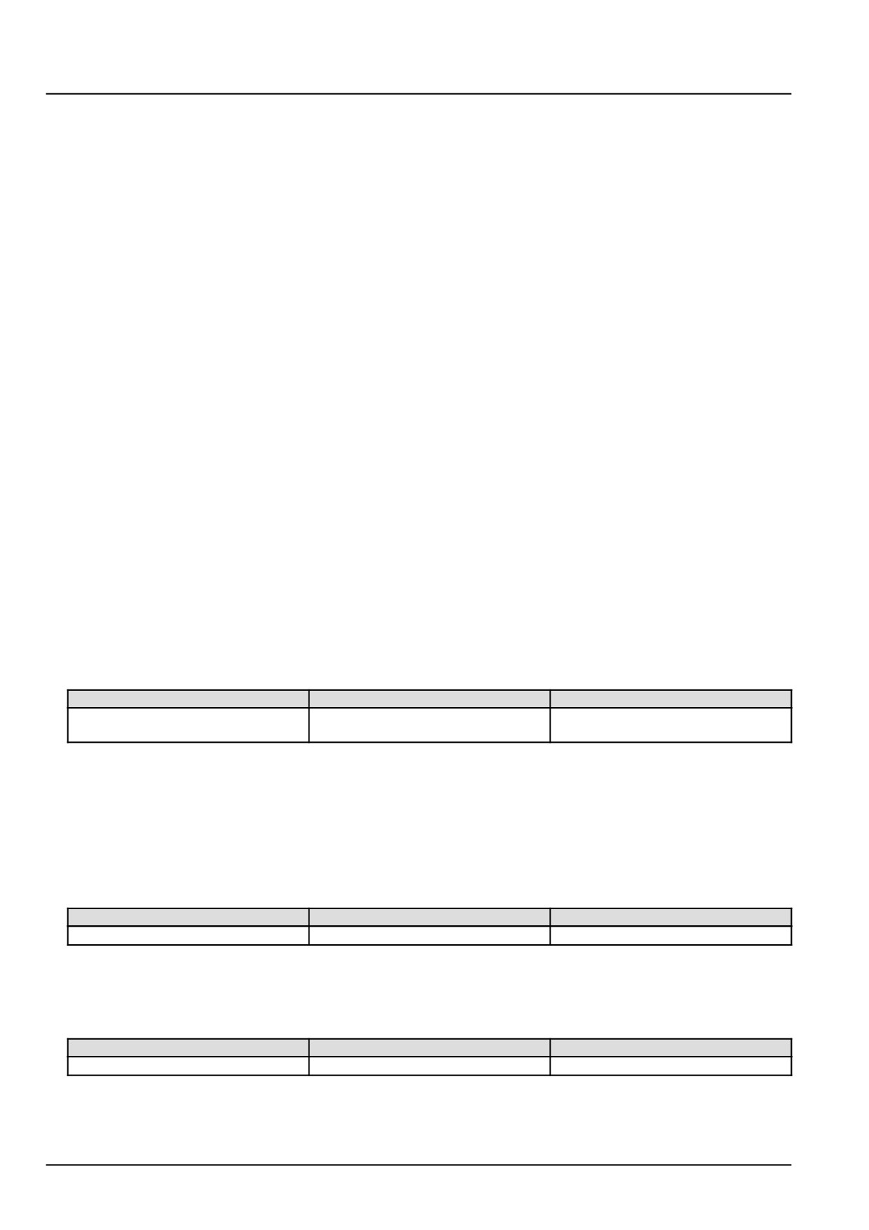
From
To
Value
X-9120 pin 85
X-9120 pin 86
There should be approximately 70 -
130 Ω.
A. If there is approximately 70 - 130 Ω, leave the relay disconnected and continue to Step 3.
B. If there is not approximately 70 - 130 Ω, the relay starter control relay K-9104 has failed. Replace the starter
control relay K-9104.
3.
Check the starter control relay K-9104 low side driver vehicle harness (VE) wiring for a short to ground condition.
With the key in the OFF position, use a multimeter to perform the following continuity check on the vehicle harness
(VE) side :
From
To
Value
X-9120 pin 85
Chassis ground
There should be no continuity.
Disconnect the ECU A-9000 connector X-9102.
With the key in the OFF position, use a multimeter to perform the following continuity check on the vehicle harness
(VE) side :
From
To
Value
X-9102 pin K27
All pins in connector X-9102
There should be no continuity.
A. If there is continuity, there is a short circuit in the starter control relay K-9104 vehicle harness (VE) wiring. Use
the appropriate service manual, if necessary, to locate and repair the shorted conductor.
186
Electrical systems - FAULT CODES
B. If there is no continuity, check the ECU A-9000 for the appropriate software and re-flash, if necessary.
4. Visually inspect the relevant harnesses and connectors for damage, bent or dislocated pins, corroded terminals,
or broken wires. Verify that the connectors are fully installed. Flex the harnesses involved to reveal intermittent
breaks or shorts in the wiring concerned. Operate the machine while you monitor the display.
A. If you find damage or the display indicates other than normal display readings, then repair the damage discov-
ered during the inspection or locate and repair the other than normal display condition and verify that the error
has been resolved.
B. If you do not find damage and the display indicates only normal readings, then erase the fault code and continue
operation.
Wiring harnesses - Electrical schematic sheet 01 - Power distribution and glow plugs (engine schematics)
(55.100.DP-C.20.E.01)
Wiring harnesses - Electrical schematic sheet 02 - Engine Control Unit (ECU) power and after treatment
system (engine schematics) (55.100.DP-C.20.E.02)
187
Electrical systems - FAULT CODES
DTC 2E1-12-Starter relay low side ECU driver circuit over
temperature
Control Module : ECU
Context:
The Engine Control Unit (ECU) A-9000 controls the starter control relay K-9104 using a low side and high side driver.
If the ECU A-9000 detects an over temperature/current condition in the high side driver circuit, this fault will occur.
Cause:
The ECU A-9000 has detected an over temperature/current condition in the starter control relay K-9104 high side
driver circuit.
Possible failure modes:
1. Faulty starter control relay K-9104 wiring, short circuit.
2. Faulty starter control relay K-9104, internal failure.
3. Faulty ECU A-9000, software.
Solution:
1.
Verify fault is present and active.
Use the Electronic Service Tool (EST) to check the status of this fault.
A. If the fault is present and active, continue with Step 2.
B. If the fault is no longer present or in an inactive state, the fault may be intermittent and not currently active.
Continue with Step 6.
2.
Check the starter control relay K-9104 coil for an internal failure.
Remove the starter control relay K-9104.
Use a multimeter to measure the relay coil resistance on the starter control relay K-9104 pins :
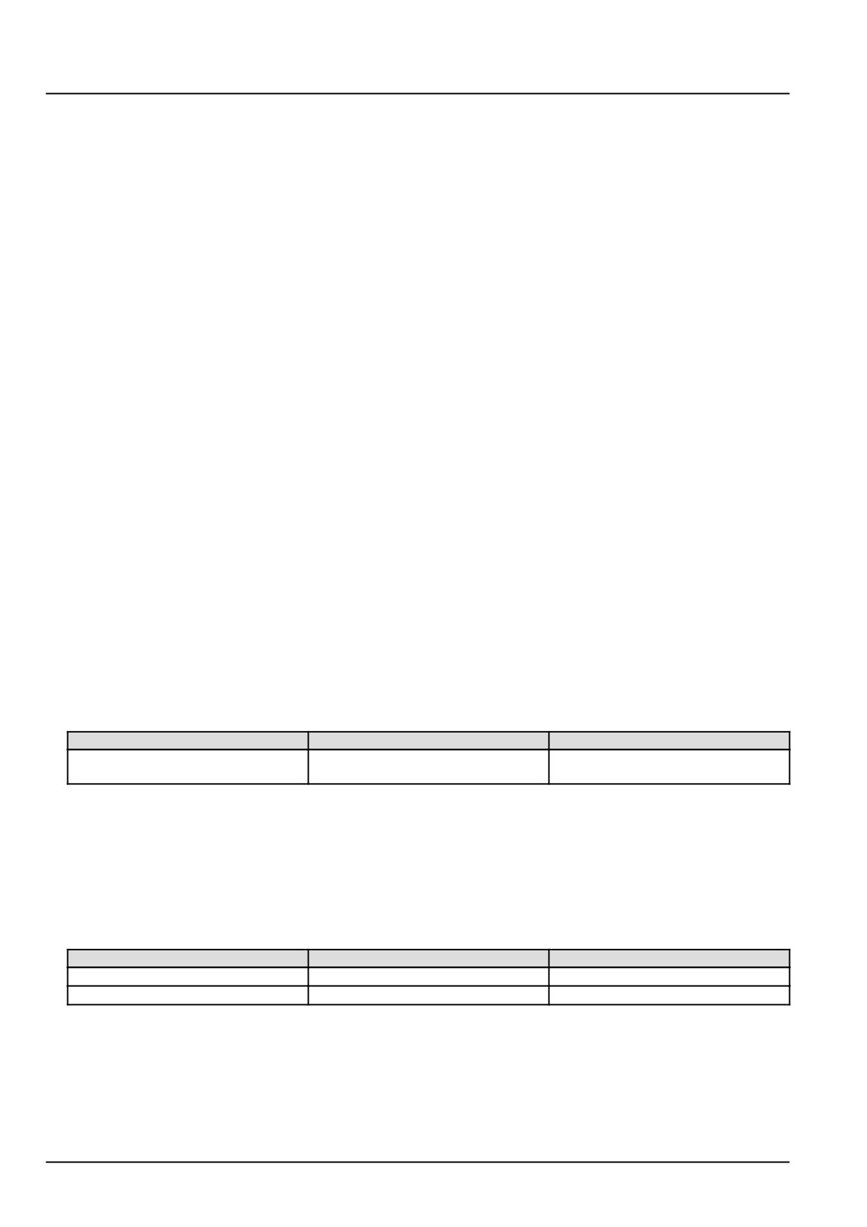
From
To
Value
X-9120 pin 85
X-9120 pin 86
There should be approximately 70 -
130 Ω.
A. If there is approximately 70 - 130 Ω, leave the starter control relay K-9104 disconnected and continue to Step
3.
B. If there is not approximately 70 - 130 Ω, the relay has failed. Replace the starter control relay K-9104.
3.
Check the starter control relay K-9104 high side driver vehicle harness (VE) wiring for a short to ground.
With the key in the OFF position, use a multimeter to perform the following continuity check for short to ground on
the vehicle harness (VE) side :
From
To
Value
X-9120 pin 85
X-9120 pin 86
There should be no continuity.
X-9120 pin 86
Chassis ground
There should be no continuity.
A. If there is continuity, there is a short to ground in the starter control relay K-9104 high side driver circuit in
the vehicle harness (VE). Use the appropriate service manual, if necessary, to locate and repair the shorted
conductor.
B. If there is no continuity, leave the starter control relay K-9104 disconnected and continue to Step 4.
4.
Check the starter control relay K-9104 high side driver vehicle harness (VE) wiring for a short to a voltage source.
188
Electrical systems - FAULT CODES
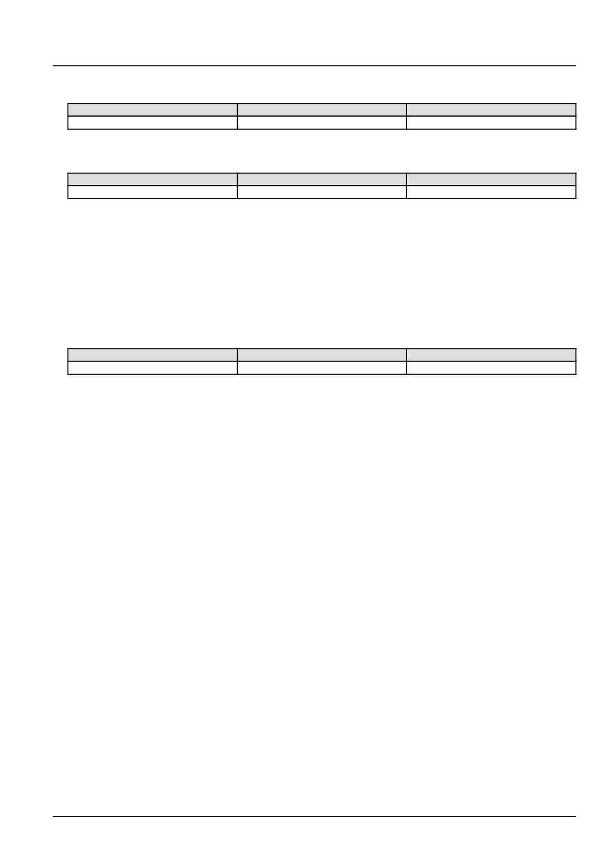
With the key in the OFF position, use a multimeter to perform the following voltage check for a short to a voltage
source on the vehicle harness (VE) side :
From
To
Value
X-9120 pin 86
Chassis ground
There should be no voltage.
With the key in the ON position, use a multimeter to perform the following voltage check for a short to a voltage
source on the vehicle harness (VE) side :
From
To
Value
X-9120 pin 86
Chassis ground
There should be no voltage.
A. If there is voltage, there is a short to a voltage source in the starter control relay K-9104 high side driver circuit
in the vehicle harness (VE). Use the appropriate service manual, if necessary, to locate and repair the shorted
conductor.
B. If there is no voltage, continue to Step 5.
5.
Check the starter control relay K-9104 low side driver vehicle harness (VE) wiring for a short circuit.
Disconnect the vehicle harness (VE) from the ECU A-9000 at connector X-9102.
With the key in the OFF position, use a multimeter to perform the following continuity check on the vehicle harness
(VE) side :
From
To
Value
X-9102 pin K53
All pins in connector X-9102
There should be no continuity.
A. If there is continuity, there is a short circuit in the starter control relay K-9104 wiring in the vehicle harness (VE).
Use the appropriate service manual, if necessary, to locate and repair the shorted conductor.
B. If there is no continuity, check the ECU A-9000 for the appropriate service manual and re-flash, if necessary.
6.
Visually inspect the relevant harnesses and connectors for damage, bent or dislocated pins, corroded terminals,
or broken wires. Verify that the connectors are fully installed. Flex the harnesses involved to reveal intermittent
breaks or shorts in the wiring concerned. Operate the machine while you monitor the display.
A. If you find damage or the display indicates other than normal display readings, then repair the damage discov-
ered during the inspection or locate and repair the other than normal display condition and verify that the error
has been resolved.
B. If you do not find damage and the display indicates only normal readings, then erase the fault code and continue
operation.
Wiring harnesses - Electrical schematic sheet 01 - Power distribution and glow plugs (engine schematics)
(55.100.DP-C.20.E.01)
Wiring harnesses - Electrical schematic sheet 02 - Engine Control Unit (ECU) power and after treatment
system (engine schematics) (55.100.DP-C.20.E.02)
189
Electrical systems - FAULT CODES
DTC 32B-02-Glow plug control circuits open
Control Module : ECU
Context:
For information regarding the functional operation of the glow plug control module Z-9101 see Glow plug system
Glow plug control module - Overview - Glow plug control module (55.202). The Engine Control Unit (ECU)
A-9000 requests operation of the glow plug control module Z-9101 via a Pulse Width Modulated (PWM) control circuit
and monitors the status of possible electrical defects via a diagnostic feedback signal from the glow plug control
module Z-9101. If the ECU A-9000 is notified of an open circuit condition in one or more of the glow plugs or glow
plug circuits, this fault will occur.
Cause:
The glow plug control module Z-9101 has communicated to the ECU A-9000, via a diagnostic connection, that an
open circuit condition exists in one or more of the glow plugs or glow plug circuits.
Possible failure modes:
1. Faulty glow plug, internal failure.
2. Faulty glow plug control circuit wiring, open circuit.
3. Faulty ECU A-9000, software.
Solution:
1.
Verify that the fault is present and active.
Use the Electronic Service Tool (EST) to check the status of this fault.
A. If the fault is present and active, continue with Step 2.
B. If the fault is no longer present or in an inactive state, the fault may be intermittent and not currently active.
Continue with Step 5.
2.
Check each of the glow plugs for an open circuit condition.
Disconnect the vehicle harness (VE) from each of the glow plugs at connectors X-9034, X-9035, and X-9036.
Use a multimeter to measure the resistance of the glow plugs on the glow plug pin :
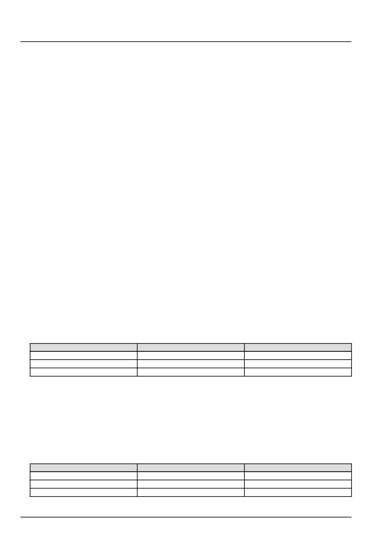
From
To
Result
X-9034 pin 1
chassis ground
There should be 0.2 - 5.0 Ω.
X-9035 pin 1
chassis ground
There should be 0.2 - 5.0 Ω.
X-9036 pin 1
chassis ground
There should be 0.2 - 5.0 Ω.
A. If there is a nominal amount of resistance measured on each of the glow plugs, leave all of the glow plugs
disconnected and continue with Step 3.
B. If there is infinite resistance measured on any of the glow plugs, that glow plug has failed internally, replace
the faulted glow plug.
3.
Check the glow plug control circuits for an open circuit condition.
Disconnect the vehicle harness (VE) from the glow plug control module Z-9101 at connector X-9113.
Use a multimeter to perform the following continuity check for an open circuit on the vehicle harness (VE) side :
From
To
Result
X-9113 pin 2
X-9034 pin 1
There should be continuity.
X-9113 pin 7
X-9035 pin 1
There should be continuity.
X-9113 pin 1
X-9036 pin 1
There should be continuity.
190
Electrical systems - FAULT CODES
A. If there is continuity on all of the checks, continue to Step 4.
B. If there is no continuity on one or more of the checks, there is an open circuit condition in the vehicle harness
(VE) between the glow plug control module Z-9101 and the respective glow plug. Locate and repair the broken
conductor.
4. Replace the glow plug control module Z-9101, then use EST to check to see that this fault has been resolved.
A. If the fault has been resolved, return the machine to service.
B. If the fault has not been resolved, check the ECU A-9000 for the appropriate software and re-flash, if necessary.
5. Visually inspect the relevant harnesses and connectors for damage, bent or dislocated pins, corroded terminals,
or broken wires. Verify that the connectors are fully installed. Flex the harnesses involved to reveal intermittent
breaks or shorts in the wiring concerned. Operate the machine while you monitor the display.
A. If you find damage or the display indicates other than normal display readings, then repair the damage discov-
ered during the inspection or locate and repair the other than normal display condition and verify that the error
has been resolved.
B. If you do not find damage and the display indicates only normal readings, then erase the fault code and continue
operation.
Wiring harnesses - Electrical schematic sheet 01 - Power distribution and glow plugs (engine schematics)
(55.100.DP-C.20.E.01)
191

Electrical systems - FAULT CODES
DTC 32B-03-Glow plug control circuits shorted to battery
Control Module : ECU
Context:
For information regarding the functional operation of the glow plug control module Z-9101 see Glow plug system
Glow plug control module - Overview - Glow plug control module (55.202). The Engine Control Unit (ECU)
A-9000 requests operation of the glow plug control module Z-9101 via a Pulse Width Modulated (PWM) control circuit
and monitors the status of possible electrical defects via a diagnostic feedback signal from the glow plug control
module Z-9101. If the ECU A-9000 is notified of a short to a voltage source condition in one or more of the glow plug
circuits, this fault will occur.
Cause:
The glow plug control module Z-9101 has communicated to the ECU A-9000, via a diagnostic connection, that a short
circuit to a voltage source condition exists in one or more of the glow plug circuits.
Possible failure modes:
1. Faulty glow plug control circuit wiring, short to a voltage source.
2. Faulty glow plug control module Z-9101, internal failure.
3. Faulty ECU A-9000, software.
Solution:
1.
Verify that the fault is present and active.
Use the Electronic Service Tool (EST) to check the status of this fault.
A. If the fault is present and active, continue with Step 2.
B. If the fault is no longer present or in an inactive state, the fault may be intermittent and not currently active.
Continue with Step 4.
2.
Check each of the glow plug circuits for a short to a voltage source condition.
Disconnect the vehicle harness (VE) from the glow plug control module Z-9101 at connector X-9113.
Disconnect the vehicle harness (VE) from each of the glow plugs.
With the key in the ON position, use a multimeter to perform the following voltage check for a short to a voltage
source on the vehicle harness (VE) side :
From
To
Result
X-9034 pin 1
chassis ground
There should be no voltage.
X-9035 pin 1
chassis ground
There should be no voltage.
X-9036 pin 1
chassis ground
There should be no voltage.
A. If there is voltage measured on any of the checks, there is a short to a voltage source condition in the glow
plug circuit wiring in the vehicle harness (VE). Locate and repair the shorted conductor.
B. If there is no voltage measured on any of the checks, continue to Step 3.
3.
Replace the glow plug control module Z-9101, then use EST to check to see that this fault has been resolved.
A. If the fault has been resolved, return the machine to service.
B. If the fault has not been resolved, check the ECU A-9000 for the appropriate software and re-flash, if necessary.
4.
Visually inspect the relevant harnesses and connectors for damage, bent or dislocated pins, corroded terminals,
or broken wires. Verify that the connectors are fully installed. Flex the harnesses involved to reveal intermittent
breaks or shorts in the wiring concerned. Operate the machine while you monitor the display.
192
Electrical systems - FAULT CODES
A. If you find damage or the display indicates other than normal display readings, then repair the damage discov-
ered during the inspection or locate and repair the other than normal display condition and verify that the error
has been resolved.
B. If you do not find damage and the display indicates only normal readings, then erase the fault code and continue
operation.
Wiring harnesses - Electrical schematic sheet 01 - Power distribution and glow plugs (engine schematics)
(55.100.DP-C.20.E.01)
193
Electrical systems - FAULT CODES
DTC 32B-04-Glow plug control circuits shorted to ground
Control Module : ECU
Context:
The Engine Control Unit (ECU) A-9000 requests operation of the glow plug control module Z-9101 via a Pulse Width
Modulated (PWM) control circuit and monitors the status of possible electrical defects via a diagnostic feedback signal
from the glow plug control module Z-9101. If the ECU A-9000 is notified of a short to ground condition in one or
more of the glow plug circuits, this fault will occur. For information regarding the functional operation of the glow plug
control module Z-9101 see Glow plug system Glow plug control module - Overview - Glow plug control module
(55.202).
Cause:
The glow plug control module Z-9101 has communicated to the ECU A-9000, via a diagnostic connection, that a short
to ground circuit condition exists in one or more of the glow plugs or glow plug circuits.
Possible failure modes:
1. Faulty glow plug, internal failure.
2. Faulty glow plug control circuit wiring, short to ground condition.
3. Faulty ECU A-9000, software.
Solution:
1.
Verify that the fault is present and active.
Use the Electronic Service Tool (EST) to check the status of this fault.
A. If the fault is present and active, continue with Step 2.
B. If the fault is no longer present or in an inactive state, the fault may be intermittent and not currently active.
Continue with Step 5.
2.
Check each of the glow plugs for a short to ground condition.
Disconnect the vehicle harness (VE) from each of the glow plugs at connectors X-9034, X-9035, and X-9036.
Use a multimeter to measure the resistance of each glow plug on the glow plug pin :
From
To
Result
X-9034 pin 1
chassis ground
There should be 0.2 - 5.0 Ω.
X-9035 pin 1
chassis ground
There should be 0.2 - 5.0 Ω.
X-9036 pin 1
chassis ground
There should be 0.2 - 5.0 Ω.
A. If there is a nominal amount of resistance measured on each of the glow plugs, leave all of the glow plugs
disconnected and continue with Step 3.
B. If there is less than 0.2 Ω resistance measured on any of the glow plugs, that glow plug has failed internally,
replace the faulted glow plug.
3.
Check the glow plug control circuits in the vehicle harness (VE) for a short to ground circuit condition.
Disconnect the vehicle harness (VE) from the glow plug control module Z-9101 at connector X-9113.
With the key in the OFF position, use a multimeter to check for a short to ground condition on the vehicle harness
(VE) side :
From
To
Result
X-9113 pin 2
chassis ground
There should be no continuity.
X-9113 pin 7
chassis ground
There should be no continuity.
X-9113 pin 1
chassis ground
There should be no continuity.
194
Electrical systems - FAULT CODES
A. If there is continuity, there is a short to ground condition in the glow plug control circuit wiring in the vehicle
harness (VE). Use the appropriate service manual, if necessary, to locate and repair the grounded conductor.
B. If there is no continuity on all of the checks, continue with Step 4.
4. Replace the glow plug control module Z-9101, then use EST to check to see that this fault has been resolved.
A. If the fault has been resolved, return the machine to service.
B. If the fault has not been resolved, check the ECU A-9000 for the appropriate software and re-flash, if necessary.
5. Visually inspect the relevant harnesses and connectors for damage, bent or dislocated pins, corroded terminals,
or broken wires. Verify that the connectors are fully installed. Flex the harnesses involved to reveal intermittent
breaks or shorts in the wiring concerned. Operate the machine while you monitor the display.
A. If you find damage or the display indicates other than normal display readings, then repair the damage discov-
ered during the inspection or locate and repair the other than normal display condition and verify that the error
has been resolved.
B. If you do not find damage and the display indicates only normal readings, then erase the fault code and continue
operation.
Wiring harnesses - Electrical schematic sheet 01 - Power distribution and glow plugs (engine schematics)
(55.100.DP-C.20.E.01)
195
Electrical systems - FAULT CODES
DTC 32B-12-Glow plug control circuits shorted
Control Module : ECU
Context:
For information regarding the functional operation of the glow plug control module Z-9101 see Glow plug system
Glow plug control module - Overview - Glow plug control module (55.202). The Engine Control Unit (ECU)
A-9000 requests operation of the glow plug control module Z-9101 via a Pulse Width Modulated (PWM) control circuit
and monitors the status of possible electrical defects via a diagnostic feedback signal from the glow plug control
module Z-9101. If the ECU A-9000 is notified of a short circuit to ground, over current, condition in one or more of the
glow plugs or glow plug circuits, this fault will occur.
Cause:
The glow plug control module Z-9101 has communicated to the ECU A-9000, via a diagnostic connection, that a short
to ground circuit condition exists in one or more of the glow plugs or glow plug circuits.
Possible failure modes:
1. Faulty glow plug, internal failure.
2. Faulty glow plug control circuit wiring, short circuit.
3. Faulty ECU A-9000, software.
Solution:
1.
Verify that the fault is present and active.
Use the Electronic Service Tool (EST) to check the status of this fault.
A. If the fault is present and active, continue with Step 2.
B. If the fault is no longer present or in an inactive state, the fault may be intermittent and not currently active.
Continue with Step 5.
2.
Check each of the glow plugs for a short to ground condition.
Disconnect the vehicle harness (VE) from each of the glow plugs at connectors X-9034, X-9035, and X-9036.
Use a multimeter to measure the resistance of each glow plug on the glow plug pin :
From
To
Result
X-9034 pin 1
chassis ground
There should be 0.2 - 5.0 Ω.
X-9035 pin 1
chassis ground
There should be 0.2 - 5.0 Ω.
X-9036 pin 1
chassis ground
There should be 0.2 - 5.0 Ω.
A. If there is a nominal amount of resistance measured on each of the glow plugs, leave all of the glow plugs
disconnected and continue with Step 3.
B. If there is less than 0.2 Ω resistance measured on any of the glow plugs, that glow plug has failed internally,
replace the failed glow plug.
3.
Check the glow plug control circuits in the vehicle harness (VE) for a short to ground circuit condition.
Disconnect the vehicle harness (VE) from the glow plug control module Z-9101 at connector X-9113.
With the key in the OFF position, use a multimeter to check for a short to ground condition on the vehicle harness
(VE) side :
From
To
Result
X-9113 pin 2
chassis ground
There should be no continuity.
X-9113 pin 7
chassis ground
There should be no continuity.
X-9113 pin 1
chassis ground
There should be no continuity.
196
Electrical systems - FAULT CODES
A. If there is continuity, there is a short to ground condition in the glow plug control circuit wiring in the vehicle
harness (VE). Use the appropriate service manual, if necessary, to locate and repair the grounded conductor.
B. If there is no continuity on all of the checks, continue with Step 4.
4. Replace the glow plug control module Z-9101, then use EST to check to see that this fault has been resolved.
A. If the fault has been resolved, return the machine to service.
B. If the fault has not been resolved, check the ECU A-9000 for the appropriate software and re-flash, if necessary.
5. Visually inspect the relevant harnesses and connectors for damage, bent or dislocated pins, corroded terminals,
or broken wires. Verify that the connectors are fully installed. Flex the harnesses involved to reveal intermittent
breaks or shorts in the wiring concerned. Operate the machine while you monitor the display.
A. If you find damage or the display indicates other than normal display readings, then repair the damage discov-
ered during the inspection or locate and repair the other than normal display condition and verify that the error
has been resolved.
B. If you do not find damage and the display indicates only normal readings, then erase the fault code and continue
operation.
Wiring harnesses - Electrical schematic sheet 01 - Power distribution and glow plugs (engine schematics)
(55.100.DP-C.20.E.01)
197
Electrical systems - FAULT CODES
DTC 359-04-Fuel metering unit is shorted to ground at the low side
Control Module : ECU
Context:
The Engine Control Unit (ECU) A-9000 monitors the fuel metering unit Y-9000 low side driver circuit. If the ECU
A-9000 detects a short to ground in the fuel metering unit Y-9000 low side driver circuit, this fault will occur.
Cause:
The ECU A-9000 has detected a short to ground condition in the fuel metering unit Y-9000 low side driver circuit.
Possible failure modes:
1. Faulty fuel metering unit Y-9000 wiring, short to ground condition.
2. Faulty fuel metering unit Y-9000, internal failure.
3. Faulty ECU A-9000, software.
Solution:
1.
Verify fault is present and active.
Use the Electronic Service Tool (EST) to check the status of this fault.
A. If the fault is present and active, continue with Step 2.
B. If the fault is no longer present or in an inactive state, the fault may be intermittent and not currently active.
Continue with Step 4.
2.
Test the fuel metering unit Y-9000 internal resistance and for a grounded condition.
Disconnect the engine harness (EN) from the fuel metering unit Y-9000 at connector X-9007 .
Use a multimeter to perform the following continuity and resistance check on the fuel metering unit Y-9000 pins :
From
To
Value
X-9007 pin 2
Chassis ground
There should be no continuity.
X-9007 pin 1
X-9007 pin 2
There should be between 2.6 - 3.2 Ω
at approximately 20 °C (68 °F).
A. If there is between 2.6 - 3.2 Ω and there is no continuity to ground, leave connector X-9007 disconnected and
continue to Step 3.
B. If the specified values are not measured, the fuel metering unit Y-9000 has a grounded condition or has failed
internally. Replace the fuel metering unit Y-9000.
3.
Check the fuel metering unit Y-9000 engine harness (EN) wiring for a short to ground condition.
Disconnect the vehicle harness (VE) from the ECU A-9000 at connector X-9001.
With the key switch in the OFF position, use a multimeter to perform the following continuity check on the engine
harness (EN) side :
From
To
Value
X-9007 pin 1
Chassis ground
There should be no continuity.
X-9001 pin A60
All pins in connector X-9001
There should be no continuity.
A. If there is continuity, there is a short circuit condition in the fuel metering unit Y-9000 vehicle harness (VE)
wiring. Use the appropriate service manual, if necessary, to locate and repair the shorted conductor.
B. If there is no continuity, check the ECU A-9000 for the appropriate software and re-flash, if necessary.
198
Electrical systems - FAULT CODES
4. Visually inspect the relevant harnesses and connectors for damage, bent or dislocated pins, corroded terminals,
or broken wires. Verify that the connectors are fully installed. Flex the harnesses involved to reveal intermittent
breaks or shorts in the wiring concerned. Operate the machine while you monitor the display.
A. If you find damage or the display indicates other than normal display readings, then repair the damage discov-
ered during the inspection or locate and repair the other than normal display condition and verify that the error
has been resolved.
B. If you do not find damage and the display indicates only normal readings, then erase the fault code and continue
operation.
Wiring harnesses - Electrical schematic sheet 03 - Engine sensors and fuel injection (engine schematics)
(55.100.DP-C.20.E.03)
199
Electrical systems - FAULT CODES
DTC 35A-03-Error in comparing energizing time to maximum value
for injector in cylinder 2
Control Module : ECU
Context:
The Zero Fuel Calibration (ZFL) evaluates energizing time for injectors at low idle. The ZFL uses learned calibration
values to change the energizing time of the pilot fuel injection. If the Engine Control Unit (ECU) A-9000 determines
that there is an error during this process, this fault will occur.
Cause:
The ECU A-9000 has determined that there is an error in the ZFL process for fuel injector number 2 Y-9002.
Solution:
1. Verify that the correct IMA injector code has been programmed to injector number 2.
A. If the correct IMA code is present, continue to Step 2.
B. If the correct IMA code has not been uploaded, program the correct IMA code.
NOTE: The IMA code may be under the paint on the fuel injector.
NOTE: For more information regarding programming IMA codes, see Fuel injectors - Configure - IMA codes
(10.218).
2. Replace the fuel injector number 2 Y-9002.
Use the Electronic Service Tool (EST) to verify the status of this fault.
A. If the fault has been resolved, return the machine to service.
B. If the fault has not been resolved, continue to Step 3.
3. Check the ECU A-9000 for the appropriate software and re-flash, if necessary.
A. If the fault has been resolved, return the machine to service.
B. If the fault has not been resolved, escalate an ASIST concern.
200
Electrical systems - FAULT CODES
DTC 35A-04-Error in comparing energizing time to minimum value
for injector in cylinder 2
Control Module : ECU
Context:
The Zero Fuel Calibration (ZFL) evaluates energizing time for injectors at low idle. The ZFL uses learned calibration
values to change the energizing time of the pilot fuel injection. If the Engine Control Unit (ECU) A-9000 determines
that there is an error during this process, this fault will occur.
Cause:
The ECU A-9000 has determined that there is an error in the ZFL process for fuel injector number 2 Y-9002.
Solution:
1. Verify that the correct IMA injector code has been programmed to injector number 2.
A. If the correct IMA code is present, continue to Step 2.
B. If the correct IMA code has not been uploaded, program the correct IMA code.
NOTE: The IMA code may be under the paint on the fuel injector.
NOTE: For more information regarding programming IMA codes, see Fuel injectors - Configure - IMA codes
(10.218).
2. Replace the fuel injector number 2 Y-9002.
Use the Electronic Service Tool (EST) to verify the status of this fault.
A. If the fault has been resolved, return the machine to service.
B. If the fault has not been resolved, continue to Step 3.
3. Check the ECU A-9000 for the appropriate software and re-flash, if necessary.
A. If the fault has been resolved, return the machine to service.
B. If the fault has not been resolved, escalate an ASIST concern.
201
Electrical systems - FAULT CODES
DTC 35D-03-PMCat Inducement warning
Control Module : ECU
Context:
The Engine Control Unit (ECU) monitors the Particulate Matter (PM) catalytic converter efficiency. If the ECU A-9000
detects an failure of efficiency, an inducement warning will be triggered and this fault will occur. Other active faults
may have caused this fault to occur.
202
Electrical systems - FAULT CODES
DTC 37F-12-Missing adjustment value programming for injector in
cylinder 3
Control Module : ECU
Context:
The Engine Control Unit (ECU) A-9000 uses an IMA code to correct fuel trim for each fuel injector equipped with the
engine at every key ON. If the ECU A-9000 determines that this trim correction for fuel injector number 3 Y-9003 can
not be performed, this fault will occur.
Cause:
The ECU A-9000 has determined that the fuel injector number 3 Y-9003 fuel trim correction can not be performed.
Solution:
1. Use the Electronic Service Tool (EST) ensure that the correct IMA code is programmed to fuel injector number 3
Y-9003.
A. If the correct code is not programmed. Use the EST to program the correct code.
B. If the correct code is programmed, continue to Step 2.
NOTE: The IMA code may be under the paint on the fuel injector.
NOTE: For more information regarding programming IMA codes, see Fuel injectors - Configure - IMA codes
(10.218).
2. Check the ECU A-9000 for the appropriate software and re-flash, if necessary.
A. If the fault has been resolved, return the machine to service.
B. If the fault has not been resolved, escalate an ASIST concern.
203
Electrical systems - FAULT CODES
DTC 3C8-02-CAN communication failure between vehicle controller
and ECU controller - TSC1_VE message
Control Module : ECU
Context:
The Engine Control Unit (ECU) A-9000 is capable of connecting to and communicating on two separate Controller
Area Networks (CAN). Proper configuration and monitoring of the two twisted pair configured networks is also a func-
tion of the ECU A-9000. CAN Node A Bus is the main vehicle interface bus. The ECU A-9000 provides a CAN
termination resistor for the CAN Node A Bus, internal to the ECU A-9000. If the ECU A-9000 senses that CAN Node
A Bus is not functioning properly, this fault will occur.
Cause:
ECU A-9000 has sensed a timeout of required vehicle controller data provided on CAN Node A.
Possible failure modes:
1. Faulty supply voltage or ground, missing.
2. Faulty CAN circuit wiring, open circuit, short to ground, or short circuit.
3. Faulty ECU A-9000, termination resistor or software.
Solution:
1.
Verify fault is present and in active state.
Use the Electronic Service Tool (EST) to check the status of this fault.
A. If the fault is present and active, continue with Step 2.
B. If the fault is no longer present or is in an inactive state, the fault may be intermittent and not currently active.
Continue with Step 5.
2.
Check for other vehicle CAN faults.
Use the EST to determine if vehicle CAN faults exist.
A. If other vehicle CAN faults do exist, resolve those vehicle CAN faults first, then check to see that this fault is
also resolved.
B. If other vehicle CAN faults do not exist, continue with Step 3.
3.
Check the ECU A-9000 supply voltage.
Disconnect the vehicle (VE) harness from the ECU A-9000 at connector X-9102.
To energize the Main relay K-9102, place a jumper wire between the vehicle harness (VE) side of connector X-9102
pin K28 and chassis ground.
Use a multimeter to check for voltage on the vehicle (VE) harness side:
From
To
Value
X-9102 pin K01
X-9102 pin K02
There should be approximately
12.0 V.
X-9102 pin K03
X-9102 pin K04
There should be approximately
12.0 V.
X-9102 pin K05
X-9102 pin K06
There should be approximately
12.0 V.
A. If the voltage is present on all of the checks, leave connector X-9102 disconnected and continue with Step 4.
204