New Holland Tractor Workmaster 50 / Workmaster 60 / Workmaster 70 / Tier 4B (final). SERVICE MANUAL - page 21
Electrical systems - FAULT CODES
From
To
Value
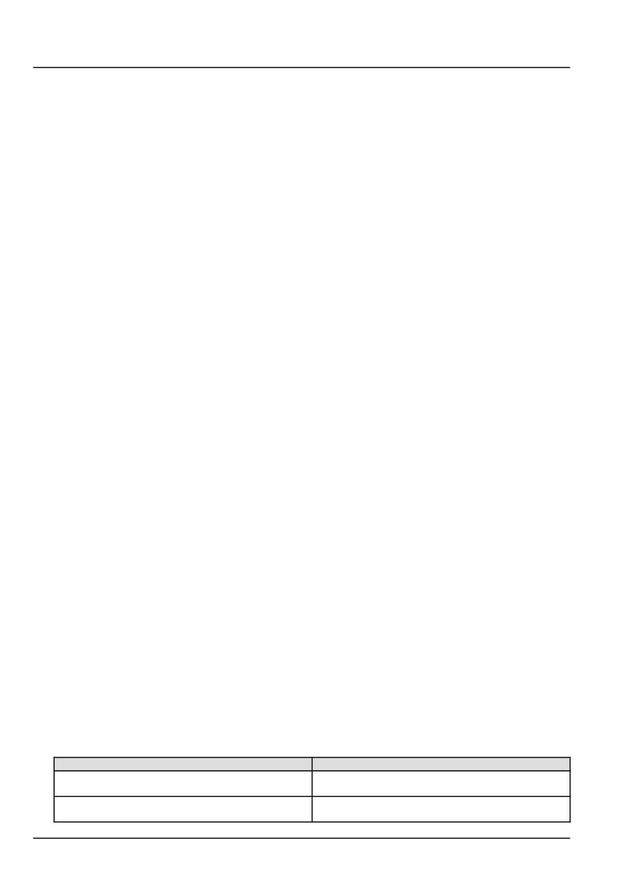
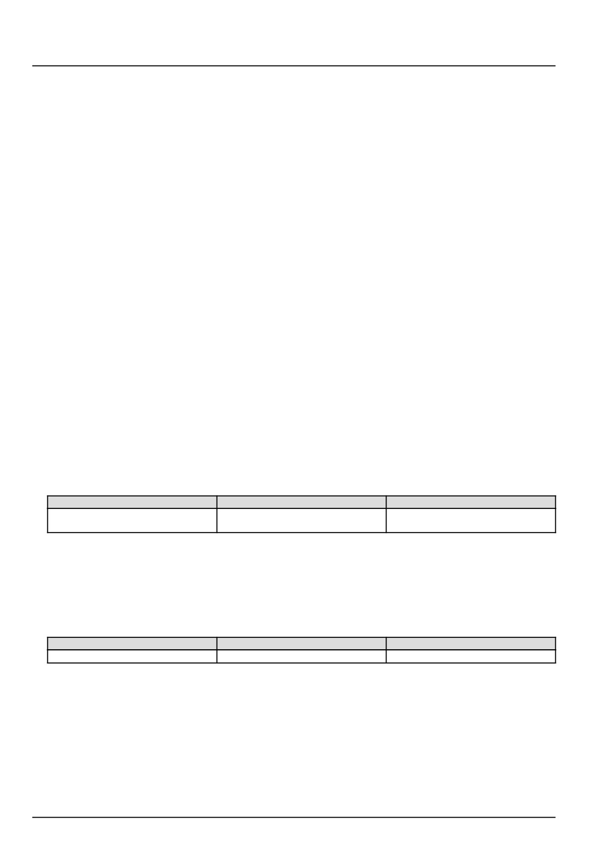
X-9102 pin K53
All pins in connector X-9102
There should be no continuity.
A. If there is continuity, there is a short to ground in the starter control relay K-9104 wiring in the vehicle harness
(VE). Use the appropriate service manual, if necessary, to locate and repair the shorted conductor.
B. If there is no continuity, check the ECU A-9000 for the appropriate service manual and re-flash, if necessary.
5. Visually inspect the relevant harnesses and connectors for damage, bent or dislocated pins, corroded terminals,
or broken wires. Verify that the connectors are fully installed. Flex the harnesses involved to reveal intermittent
breaks or shorts in the wiring concerned. Operate the machine while you monitor the display.
A. If you find damage or the display indicates other than normal display readings, then repair the damage discov-
ered during the inspection or locate and repair the other than normal display condition and verify that the error
has been resolved.
B. If you do not find damage and the display indicates only normal readings, then erase the fault code and continue
operation.
Wiring harnesses - Electrical schematic sheet 01 - Power distribution and glow plugs (engine schematics)
(55.100.DP-C.20.E.01)
Wiring harnesses - Electrical schematic sheet 02 - Engine Control Unit (ECU) power and after treatment
system (engine schematics) (55.100.DP-C.20.E.02)
125
Electrical systems - FAULT CODES
DTC 1E3-03-Fuel injection requested during overrun
Control Module : ECU
Context:
The Engine Control Unit (ECU) A-9000, during after run, monitors fuel injector actuation time by calculating the de-
manded fuel injection quantity of actual injection and actual fuel pressure. If the ECU A-9000 determines that ener-
gizing time is greater than engine speed, this fault will occur.
Solution:
1. Check the ECU A-9000 for the appropriate software and re-flash, if necessary.
A. If the fault has been resolved, return the machine to service.
B. If the fault has not been resolved, escalate an ASIST concern.
126
Electrical systems - FAULT CODES
DTC 1E4-03-ECU internal failure - Calculated engine speed
Control Module : ECU
Context:
The Engine Control Unit (ECU) A-9000 monitors engine speed in multiple software levels. If the ECU A-9000 deter-
mines that there is plausibility error in the engine speed monitoring, this fault will occur.
Solution:
1. Check the ECU A-9000 for the appropriate software and re-flash, if necessary.
A. If the fault has been resolved, return the machine to service.
B. If the fault has not been resolved, escalate an ASIST concern.
127
Electrical systems - FAULT CODES
DTC 1E6-12-ECU 5 volt sensor supply 1 out of range
Control Module : ECU
Context:
The Engine Control Unit (ECU) A-9000 provides three independent five volt sensor supplies. The ECU A-9000 mon-
itors each sensor supply voltage to ensure they operate within a given range. If the ECU A-9000 determines that the
voltage for sensor supply 1 is out of range, this fault will occur.
The ECU A-9000 pin numbers associated with sensor supply 1 are A07, A08, A09, A10, A11, A12, and A13.
Cause:
The ECU A-9000 has determined that the sensor supply 1 voltage is out of range.
Possible failure modes:
1. Faulty battery voltage.
2. Faulty ECU A-9000 supply voltage.
3. Faulty ECU A-9000 sensor supply 1 pins.
4. Faulty ECU A-9000 connector X-9121, corrosion or damage.
5. Faulty Throttle Valve Actuator (TVA) Z-9001, position sensor wiring or internal failure.
6. Faulty Exhaust Gas Recirculation (EGR) valve Z-9000, position sensor wiring or internal failure.
7. Faulty intake manifold pressure and temperature sensor B-9001, wiring or internal failure.
8. Faulty rail pressure sensor B-9004, wiring or internal failure.
9. Faulty exhaust manifold pressure sensor B-9005, wiring to internal failure.
10. Faulty camshaft speed sensor B-9017, wiring or internal failure.
11. Faulty ECU A-9000, software.
Solution:
1. Verify fault is present and active.
Use the Electronic Service Tool (EST) to check the status of this fault.
A. If the fault is present and active, continue with Step 2.
B. If the fault is no longer present or in an inactive state, the fault may be intermittent and not currently active.
Continue with Step 11.
2. Check the battery voltage.
Charge the battery, then, perform a load test on the battery.
A. If the battery passes the load test, continue to Step 3.
B. If the battery fails the load test, the battery has failed. Replace the battery.
3. Disconnect the ECU A-9000 connector X-9001.
Check the following pins listed below on the ECU A-9000 and in connector X-9001.
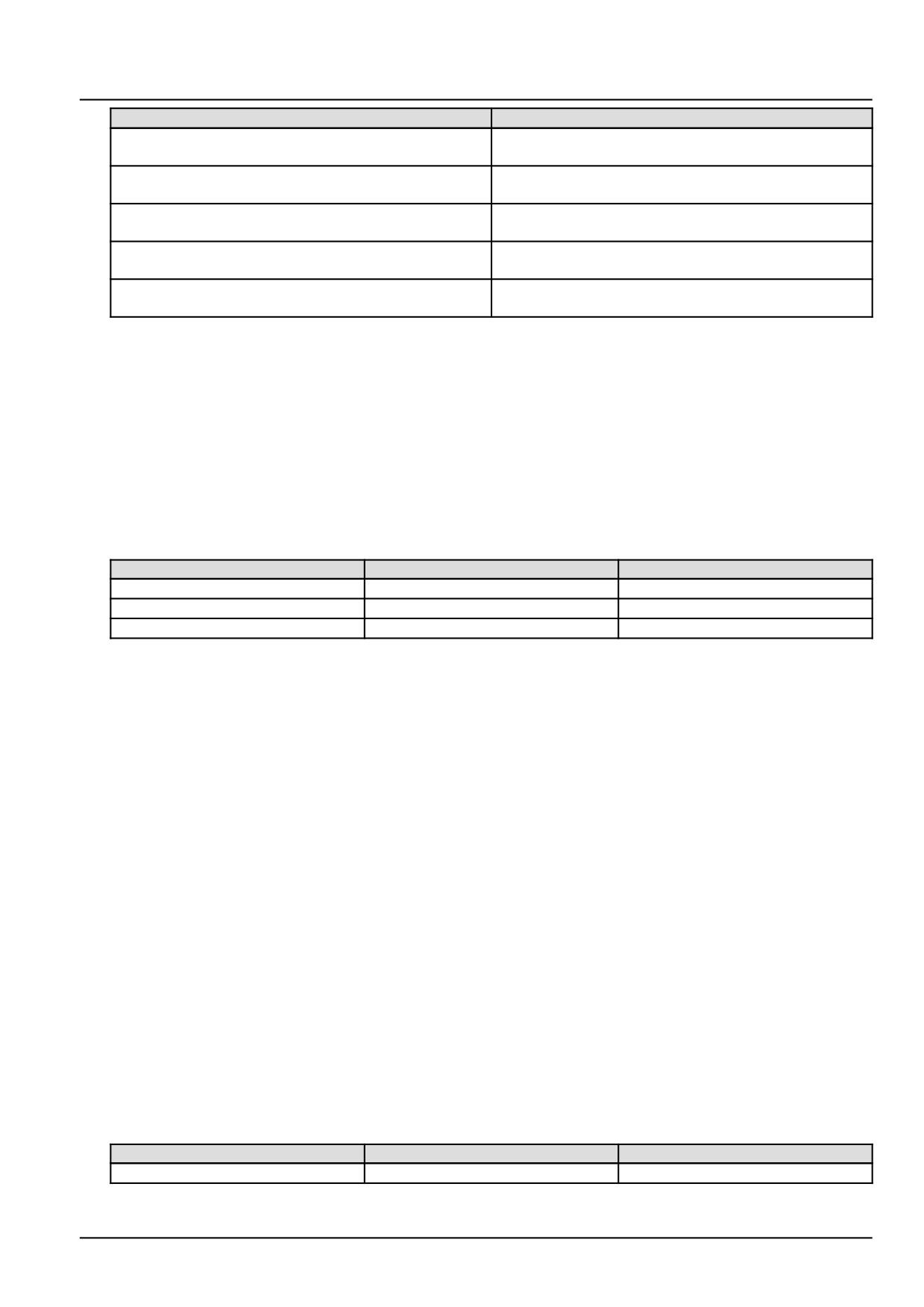
Pin
Physical condition
X-9001 pin A07
The pin and connector should be free of corrosion or
damage.
X-9001 pin A08
The pin and connector should be free of corrosion or
damage.
128
Electrical systems - FAULT CODES
Pin
Physical condition
X-9001 pin A09
The pin and connector should be free of corrosion or
damage.
X-9001 pin A10
The pin and connector should be free of corrosion or
damage.
X-9001 pin A11
The pin and connector should be free of corrosion or
damage.
X-9001 pin A12
The pin and connector should be free of corrosion or
damage.
X-9001 pin A13
The pin and connector should be free of corrosion or
damage.
A. If a pin or connector shows signs of corrosion or damage, repair as necessary.
B. If a pin or connector shows no signs of corrosion or damage, re-connect the ECU A-9000 at connector X-9001
and continue to Step 4.
4.
Check the ECU A-9000 supply voltage.
Disconnect the ECU A-9000 connector X-9102.
Place a jumper wire between X-9102 pin K28 and chassis ground. This will energize the main relay K-9102.
With the key in the ON position, use a multimeter to perform the following voltage check on the vehicle harness
(VE) side :
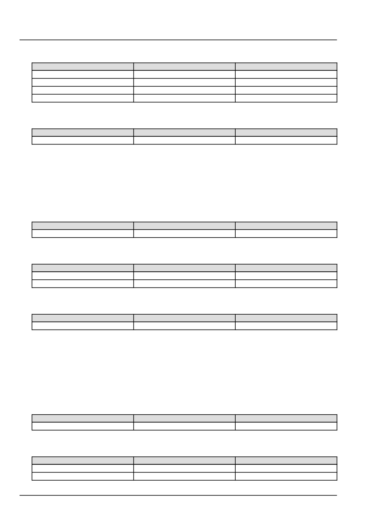
From
To
Value
X-9102 pin K03
X-9102 pin K02
There should be approximately 12 V.
X-9102 pin K05
X-9102 pin K04
There should be approximately 12 V.
X-9102 pin K01
X-9102 pin K06
There should be approximately 12 V.
A. If there is approximately 12 V, remove the jumper wire and re-connect the ECU A-9000 at connector X-9102,
then continue to Step 5.
B. If there is not approximately 12 V, there is a failure in the ECU A-9000 supply wiring. Use the appropriate
service manual, if necessary, to locate and repair the failed conductor.
5.
Disconnect each of the following connectors one at a time. Monitor the status of this fault, DTC 1E6-NPL - ECU
internal failure - Sensor 5 volt supply 1 during the check.
The TVA Z-9001 connector X-9011 .
The intake manifold pressure and temperature sensor B-9001 connector X-9003.
The rail pressure sensor B-9004 connector X-9026.
The camshaft speed sensor B-9017 connector X-9008.
A. If the fault is no longer active after a component disconnection, the relevant component has failed. Replace
the component.
B. If the fault is still active after the component disconnections, leave all of the connectors disconnected and
continue to Step 6.
6.
Check the TVA Z-9001 voltage supply wiring.
Disconnect the vehicle harness (VE) from the ECU A-9000 at connectors X-9102 and X-9001.
With the key in the ON position, use a multimeter to perform the following voltage check on the engine harness
(EN) side :
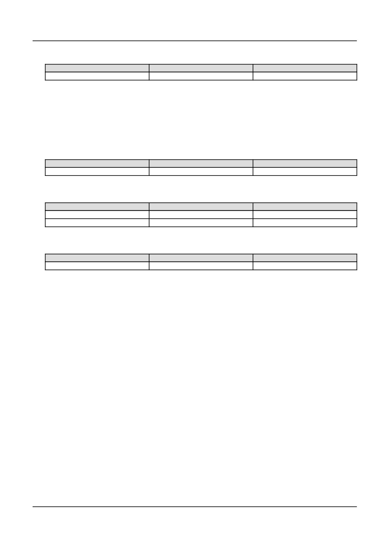
From
To
Value
X-9011 pin 1
Chassis ground
There should be no voltage.
129
Electrical systems - FAULT CODES
With the key in the OFF position, use a multimeter to perform the following continuity checks on the engine
harness (EN) side :
From
To
Value
X-9011 pin 1
Chassis ground
There should be no continuity.
X-9011 pin 1
X-9011 pin 3
There should be no continuity.
X-9011 pin 1
X-9011 pin 2
There should be no continuity.
X-9011 pin 1
X-9011 pin 6
There should be no continuity.
With the key in the OFF position, use a multimeter to perform the following continuity checks on the vehicle
harness (VE) side :
From
To
Value
X-9001 pin A08
All pins in connector X-9001.
There should be no continuity.
A. If the specified values are measured, leave the ECU A-9000 connectors X-9102 and X-9001 disconnected.
Then, continue to Step 7.
B. If the specified values are not measured, there is a failure in the TVA Z-9001 voltage supply wiring. Use the
appropriate service manual, if necessary, to locate and repair the failed conductor.
7.
Check the intake manifold pressure and temperature sensor B-9001 voltage supply wiring.
With the key in the ON position, use a multimeter to perform the following voltage check on the engine harness
(EN) side :
From
To
Value
X-9003 pin 3
Chassis ground
There should be no voltage.
With the key in the OFF position, use a multimeter to perform the following continuity checks on the engine
harness (EN) side :
From
To
Value
X-9003 pin 3
Chassis ground
There should be no continuity.
X-9003 pin 3
X-9003 pin 1
There should be no continuity.
With the key in the OFF position, use a multimeter to perform the following continuity checks on the vehicle
harness (VE) side :
From
To
Value
X-9001 pin A10
All pins in connector X-9001.
There should be no continuity.
A. If the specified values are measured, leave the ECU A-9000 connectors X-9102 and X-9001 disconnected.
Then, continue to Step 8.
B. If the specified values are not measured, there is a failure in the intake manifold pressure and temperature
sensor B-9001 voltage supply wiring. Use the appropriate service manual, if necessary, to locate and repair
the failed conductor.
8.
Check the rail pressure sensor B-9004 voltage supply wiring.
With the key in the ON position, use a multimeter to perform the following voltage check on the engine harness
(EN) side :
From
To
Value
X-9026 pin 3
Chassis ground
There should be no voltage.
With the key in the OFF position, use a multimeter to perform the following continuity checks on the engine
harness (EN) side :
From
To
Value
X-9026 pin 3
Chassis ground
There should be no continuity.
X-9026 pin 3
X-9026 pin 1
There should be no continuity.
130
Electrical systems - FAULT CODES
With the key in the OFF position, use a multimeter to perform the following continuity checks on the vehicle
harness (VE) side :
From
To
Value
X-9001 pin A11
All pins in connector X-9001.
There should be no continuity.
A. If the specified values are measured, leave the ECU A-9000 connectors X-9102 and X-9001 disconnected.
Then, continue to Step 9.
B. If the specified values are not measured, there is a failure in the rail pressure sensor B-9004 voltage supply
wiring. Use the appropriate service manual, if necessary, to locate and repair the failed conductor.
9.
Check the camshaft speed sensor B-9017 voltage supply wiring.
With the key in the ON position, use a multimeter to perform the following voltage check on the engine harness
(EN) side :
From
To
Value
X-9008 pin 3
Chassis ground
There should be no voltage.
With the key in the OFF position, use a multimeter to perform the following continuity checks on the engine
harness (EN) side :
From
To
Value
X-9008 pin 3
Chassis ground
There should be no continuity.
X-9008 pin 1
X-9008 pin 3
There should be no continuity.
With the key in the OFF position, use a multimeter to perform the following continuity checks on the vehicle
harness (VE) side :
From
To
Value
X-9001 pin A13
All pins in connector X-9001.
There should be no continuity.
A. If the specified values are measured, re-connect all of the connectors and continue to Step 10.
B. If the specified values are not measured, there is a failure in the camshaft speed sensor B-9017 voltage supply
wiring. Use the appropriate service manual, if necessary, to locate and repair the failed conductor.
10.
Check the ECU A-9000 for the appropriate software and re-flash, if necessary.
A. If the fault has been resolved, return the machine to service.
B. If the fault has not been resolved, escalate an ASIST concern.
11.
Visually inspect the relevant harnesses and connectors for damage, bent or dislocated pins, corroded terminals,
or broken wires. Verify that the connectors are fully installed. Flex the harnesses involved to reveal intermittent
breaks or shorts in the wiring concerned. Operate the machine while you monitor the display.
A. If you find damage or the display indicates other than normal display readings, Then, repair the damage
discovered during the inspection or locate and repair the other than normal display condition and verify that
the error has been resolved.
B. If you do not find damage and the display indicates only normal readings, Then, erase the fault code and
continue operation.
Wiring harnesses - Electrical schematic sheet 02 - Engine Control Unit (ECU) power and after treatment
system (engine schematics) (55.100.DP-C.20.E.02)
Wiring harnesses - Electrical schematic sheet 03 - Engine sensors and fuel injection (engine schematics)
(55.100.DP-C.20.E.03)
131
Electrical systems - FAULT CODES
DTC 1E7-03-ECU 5 volt sensor supply 2 out of range
Control Module : ECU
Context:
The Engine Control Unit (ECU) A-9000 provides three independent five volt sensor supplies. The ECU A-9000 mon-
itors each sensor supply voltage to ensure they operate within a given range. If the ECU A-9000 determines that the
voltage for sensor supply 2 is out of range, this fault will occur.
The ECU A-9000 pin numbers associated with sensor supply 2 are K12, K13, K14, K15, and K16.
Cause:
The ECU A-9000 has determined that the sensor supply 2 voltage is out of range.
Possible failure modes:
1. Faulty battery voltage.
2. Faulty ECU A-9000 supply voltage.
3. Faulty ECU A-9000 sensor supply 2 pins.
4. Faulty ECU A-9000 connector X-9102, corrosion or damage.
5. Faulty ECU A-9000, software.
Solution:
1.
Verify fault is present and active.
Use the Electronic Service Tool (EST) to check the status of this fault.
A. If the fault is present and active, continue with Step 2.
B. If the fault is no longer present or in an inactive state, the fault may be intermittent and not currently active.
Continue with Step 6.
2.
Check the battery voltage.
Charge the battery, then, perform a load test on the battery.
A. If the battery passes the load test, continue to Step 3.
B. If the battery fails the load test, the battery has failed. Replace the battery.
3.
Check the ECU A-9000 supply voltage.
Disconnect the ECU A-9000 connector X-9102.
Place a jumper wire between X-9102 pin K28 and chassis ground. This will energize the main relay K-9102.
With the key in the ON position, use a multimeter to perform the following voltage check on the vehicle harness
(VE) side :
From
To
Value
X-9102 pin K03
X-9102 pin K02
There should be approximately 12 V.
X-9102 pin K05
X-9102 pin K04
There should be approximately 12 V.
X-9102 pin K01
X-9102 pin K06
There should be approximately 12 V.
A. If there is approximately 12 V, leave the ECU A-9000 connector X-9102 disconnected and continue to Step 4.
B. If there is not approximately 12 V, there is a failure in the ECU A-9000 supply wiring. Use the appropriate
service manual, if necessary, to locate and repair the failed conductor.
132
Electrical systems - FAULT CODES
4.
Check the following pins listed below on the ECU A-9000 and in connector X-9102.
Pin
Physical condition
X-9102 pin K12
The pin and connector should be free of corrosion or
damage.
X-9102 pin K13
The pin and connector should be free of corrosion or
damage.
X-9102 pin K14
The pin and connector should be free of corrosion or
damage.
X-9102 pin K15
The pin and connector should be free of corrosion or
damage.
X-9102 pin K16
The pin and connector should be free of corrosion or
damage.
A. If a pin or connector shows signs of corrosion or damage, repair as necessary.
B. If a pin or connector shows no signs of corrosion or damage, continue to Step 5.
5.
Check the ECU A-9000 for the appropriate software and re-flash, if necessary.
A. If the fault has been resolved, return the machine to service.
B. If the fault has not been resolved, escalate an ASIST concern.
6.
Visually inspect the relevant harnesses and connectors for damage, bent or dislocated pins, corroded terminals,
or broken wires. Verify that the connectors are fully installed. Flex the harnesses involved to reveal intermittent
breaks or shorts in the wiring concerned. Operate the machine while you monitor the display.
A. If you find damage or the display indicates other than normal display readings, then repair the damage discov-
ered during the inspection or locate and repair the other than normal display condition and verify that the error
has been resolved.
B. If you do not find damage and the display indicates only normal readings, then erase the fault code and continue
operation.
Wiring harnesses - Electrical schematic sheet 02 - Engine Control Unit (ECU) power and after treatment
system (engine schematics) (55.100.DP-C.20.E.02)
133
Electrical systems - FAULT CODES
DTC 1E8-03-ECU 5 volt sensor supply 3 out of range
Control Module : ECU
Context:
The Engine Control Unit (ECU) A-9000 provides three independent five volt sensor supplies. The ECU A-9000 mon-
itors each sensor supply voltage to ensure they operate within a given range. If the ECU A-9000 determines that the
voltage for sensor supply 3 is out of range, this fault will occur.
The ECU A-9000 pin numbers associated with sensor supply 3 are K17, K18 and A29.
Cause:
The ECU A-9000 has determined that the sensor supply 3 voltage is out of range.
Possible failure modes:
1. Faulty battery voltage.
2. Faulty ECU A-9000, supply voltage.
3. Faulty ECU A-9000 sensor supply 3 pins.
4. Faulty ECU A-9000 connector X-9001 or X-9102, corrosion or damage.
5. Faulty ECU A-9000, software.
Solution:
1.
Verify fault is present and active.
Use the Electronic Service Tool (EST) to check the status of this fault.
A. If the fault is present and active, continue with Step 2.
B. If the fault is no longer present or in an inactive state, the fault may be intermittent and not currently active.
Continue with Step 6.
2.
Check the battery voltage.
Charge the battery, then, perform a load test on the battery.
A. If the battery passes the load test, continue to Step 3.
B. If the battery fails the load test, the battery has failed. Replace the battery.
3.
Check the ECU A-9000 supply voltage.
Disconnect the ECU A-9000 connector X-9102.
Place a jumper wire between X-9102 pin K28 and chassis ground. This will energize the main relay K-9102.
With the key in the ON position, use a multimeter to perform the following voltage check on the vehicle harness
(VE) side :
From
To
Value
X-9102 pin K03
X-9102 pin K02
There should be approximately 12 V.
X-9102 pin K05
X-9102 pin K04
There should be approximately 12 V.
X-9102 pin K01
X-9102 pin K06
There should be approximately 12 V.
A. If there is approximately 12 V, leave the ECU A-9000 connector X-9102 disconnected and continue to Step 4.
B. If there is not approximately 12 V, there is a failure in the ECU A-9000 supply wiring. Use the appropriate
service manual, if necessary, to locate and repair the failed conductor.
134
Electrical systems - FAULT CODES
4.
Disconnect the engine harness (EN) from the ECU A-9000 at connector X-9001.
Check the following pins listed below on the ECU A-9000 and in connectors X-9001 and X-9102.
Pin
Physical condition
X-9102 pin K17
The pin and connector should be free of corrosion or
damage.
X-9102 pin K18
The pin and connector should be free of corrosion or
damage.
X-9001 pin A29
The pin and connector should be free of corrosion or
damage.
A. If a pin or connector shows signs of corrosion or damage, repair as necessary.
B. If a pin or connector shows no signs of corrosion or damage, continue to Step 5.
5.
Check the ECU A-9000 for the appropriate software and re-flash, if necessary.
A. If the fault has been resolved, return the machine to service.
B. If the fault has not been resolved, escalate an ASIST concern.
6.
Visually inspect the relevant harnesses and connectors for damage, bent or dislocated pins, corroded terminals,
or broken wires. Verify that the connectors are fully installed. Flex the harnesses involved to reveal intermittent
breaks or shorts in the wiring concerned. Operate the machine while you monitor the display.
A. If you find damage or the display indicates other than normal display readings, Then, repair the damage dis-
covered during the inspection or locate and repair the other than normal display condition and verify that the
error has been resolved.
B. If you do not find damage and the display indicates only normal readings, Then, erase the fault code and
continue operation.
Wiring harnesses - Electrical schematic sheet 02 - Engine Control Unit (ECU) power and after treatment
system (engine schematics) (55.100.DP-C.20.E.02)
Wiring harnesses - Electrical schematic sheet 03 - Engine sensors and fuel injection (engine schematics)
(55.100.DP-C.20.E.03)
135
Electrical systems - FAULT CODES
DTC 1EB-03-ECU internal failure - Ambient pressure sensor voltage
is higher than expected
Control Module : ECU
Context:
The Engine Control Unit (ECU) A-9000 monitors atmospheric pressure. The ECU A-9000 performs a signal range
check of the atmospheric pressure sensor value. If the ECU A-9000 determines that the value is too high, this fault
will occur. The atmospheric pressure sensor is internal to the ECU A-9000.
Solution:
1. Check the ECU A-9000 for the appropriate software and re-flash, if necessary.
A. If the fault has been resolved, return the machine to service.
B. If the fault has not been resolved, escalate an ASIST concern.
136
Electrical systems - FAULT CODES
DTC 1EB-04-ECU internal failure - Ambient pressure sensor voltage
is lower than expected
Control Module : ECU
Context:
The Engine Control Unit (ECU) A-9000 monitors atmospheric pressure. The ECU A-9000 performs a signal range
check of the atmospheric pressure sensor value. If the ECU A-9000 determines that the value is too low, this fault will
occur. The atmospheric pressure sensor is internal to the ECU A-9000.
Solution:
1. Check the ECU A-9000 for the appropriate software and re-flash, if necessary.
A. If the fault has been resolved, return the machine to service.
B. If the fault has not been resolved, escalate an ASIST concern.
137
Electrical systems - FAULT CODES
DTC 1F7-00-PMCat inlet temperature sensor physical range check
high
Control Module : ECU
Context:
The Engine Control Unit (ECU) A-9000 monitors the Particulate Matter (PM) catalytic converter inlet temperature sen-
sor B-9127. If the ECU A-9000 detects a temperature greater than 1000 °C (1832 °F) from the PM catalytic converter
inlet temperature sensor B-9127, this fault will occur. If this fault is active, the last valid temperature value will be
frozen for a preliminary failure or set to a fixed replacement value of 99.96 °C (211.93 °F) if the failure is validated.
Other active faults may have caused this fault to occur.
Cause:
The ECU A-9000 has detected a temperature too high from the PM catalytic converter inlet temperature sensor
B-9127.
Possible failure modes:
1. Faulty PM catalytic converter inlet temperature sensor B-9127.
2. Faulty PM catalytic converter inlet temperature sensor B-9127, wiring harness.
3. Faulty ECU A-9000, software.
Solution:
1.
Verify fault is present and active.
Use the Electronic Service Tool (EST) to check the status of this fault.
A. If the fault is present and active, continue with Step 2.
B. If the fault is no longer present or in an inactive state, the fault may be intermittent and not currently active.
Continue with Step 6.
2.
Check the PM catalytic converter inlet temperature sensor B-9127 for an internal failure.
Disconnect the vehicle harness from the PM catalytic converter inlet temperature sensor B-9127 at connector
X-9127.
Use a multimeter to measure the resistance on the PM catalytic converter inlet temperature sensor B-9127 :
From
To
Value
X-9127 pin 1
X-9127 pin 2
There should be between 170.2 -
849.7 Ω.
A. If there is between 170.2 - 849.7 Ω, leave connector X-9127 disconnected and continue to Step 3.
B. If there is between 170.2 - 849.7 Ω, the PM catalytic converter inlet temperature sensor B-9127 has failed.
Replace the PM catalytic converter inlet temperature sensor B-9127.
3.
Check the PM catalytic converter inlet temperature sensor B-9127 vehicle harness (VE) wiring for a short circuit
to battery.
With the key in the OFF position, use a multimeter to perform the following voltage check on the vehicle harness
side :
From
To
Value
X-9127 pin 1
Chassis ground
There should be no voltage.
With the key in the ON position, use a multimeter to perform the following voltage check on the vehicle harness
side :
138
Electrical systems - FAULT CODES
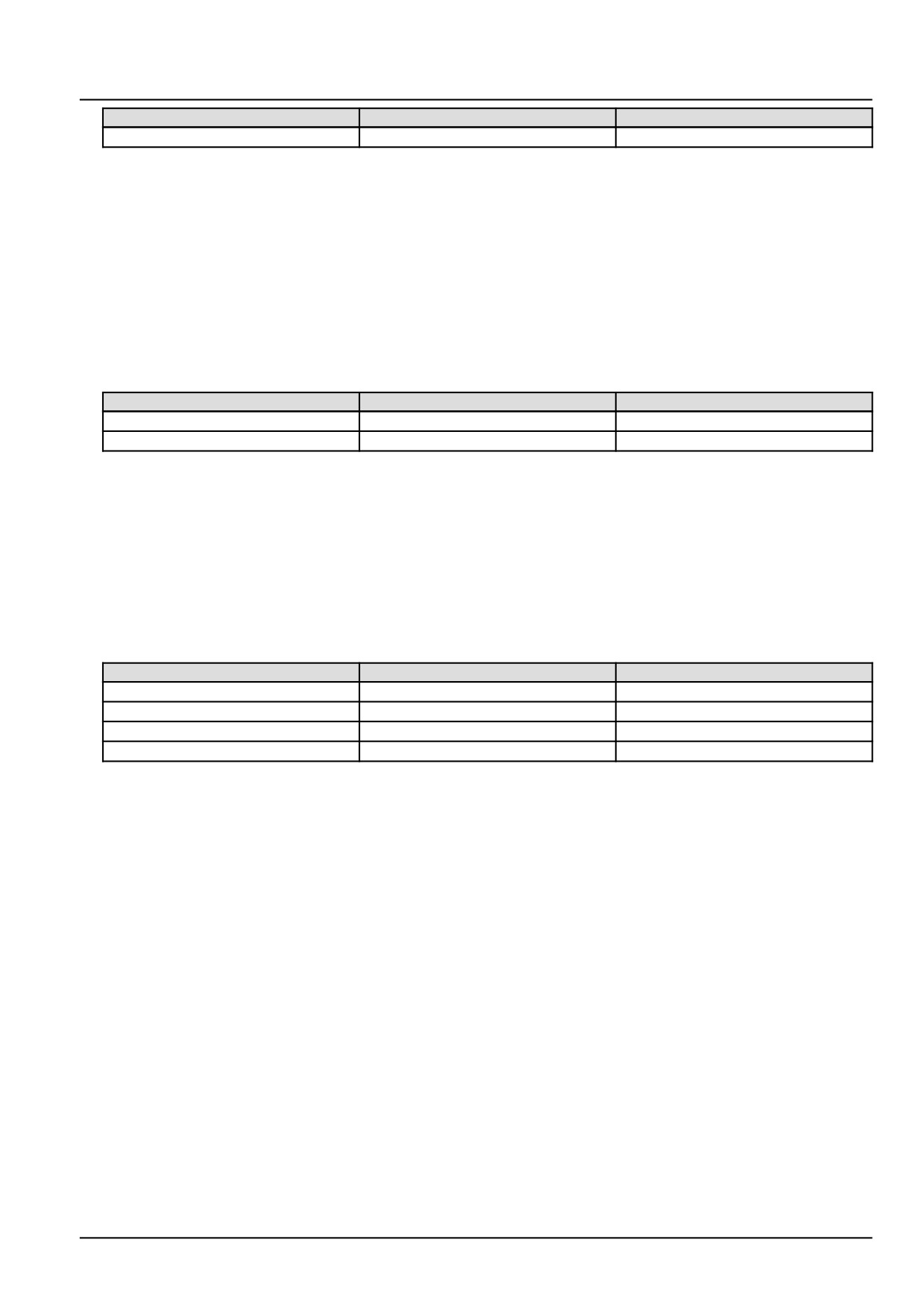
From
To
Value
X-9127 pin 1
Chassis ground
There should be less than 5.5 V
A. If the specified values are not measured, there is a short to battery in the PM catalytic converter inlet tempera-
ture sensor B-9127 wiring. Use the appropriate service manual, if necessary, to locate and repair the shorted
conductor.
B. If the specified values are measured, leave connector X-9127 disconnected and continue to Step 4.
4.
Check the PM catalytic converter inlet temperature sensor B-9127 vehicle harness (VE) wiring for an open circuit
condition.
Disconnect the vehicle harness from the ECU A-9000 at connector X-9102.
With the key in the OFF position, use a multimeter to perform the following continuity check on the vehicle harness
(VE) side :
From
To
Value
X-9127 pin 2
X-9102 pin K83
There should be continuity.
X-9127 pin 1
X-9102 pin K84
There should be continuity.
A. If there is no continuity, there is an open circuit in the PM catalytic converter inlet temperature sensor B-9127
vehicle harness (VE) wiring. Use the appropriate service manual, if necessary, to locate and repair the broken
conductor.
B. If there is continuity, leave connectors X-9102 and X-9127 disconnected and continue to Step 5.
5.
Check the PM catalytic converter inlet temperature sensor B-9127 vehicle harness (VE) wiring for a short circuit
condition.
With the key in the OFF position, use a multimeter to perform the following continuity check on the vehicle harness
(VE) side :
From
To
Value
X-9102 pin K83
All pins in connector X-9102
There should be no continuity.
X-9102 pin K84
All pins in connector X-9102
There should be no continuity.
X-9127 pin 2
X-9127 pin 1
There should be no continuity.
X-9127 pin 1
Chassis ground
There should be no continuity.
A. If there is continuity, there is a short circuit in the PM catalytic converter inlet temperature sensor B-9127 ve-
hicle harness (VE) wiring. Use the appropriate service manual, if necessary, to locate and repair the shorted
conductor.
B. If there is no continuity, check the ECU A-9000 for the appropriate software and re-flash, if necessary.
6.
Visually inspect the relevant harnesses and connectors for damage, bent or dislocated pins, corroded terminals,
or broken wires. Verify that the connectors are fully installed. Flex the harnesses involved to reveal intermittent
breaks or shorts in the wiring concerned. Operate the machine while you monitor the display.
A. If you find damage or the display indicates other than normal display readings, then repair the damage discov-
ered during the inspection or locate and repair the other than normal display condition and verify that the error
has been resolved.
B. If you do not find damage and the display indicates only normal readings, then erase the fault code and continue
operation.
Wiring harnesses - Electrical schematic sheet 02 - Engine Control Unit (ECU) power and after treatment
system (engine schematics) (55.100.DP-C.20.E.02)
139
Electrical systems - FAULT CODES
DTC 1F7-03-PMCat inlet temperature sensor voltage is higher than
expected
Control Module : ECU
Context:
The Engine Control Unit (ECU) A-9000 monitors the Particulate Matter (PM) catalytic converter inlet temperature
sensor B-9127. If the ECU A-9000 detects a voltage greater than 3.59 V in the PM catalytic converter inlet temperature
sensor B-9127 signal circuit, this fault will occur. If this fault is active, the last valid temperature value will be frozen
for a preliminary failure or set to a fixed replacement value of 99.96 °C (211.93 °F) if the failure is validated.
Cause:
The ECU A-9000 has detected a voltage greater than 3.59 V in the PM catalytic converter inlet temperature sensor
B-9127 signal circuit.
Possible failure modes:
1. Faulty PM catalytic converter inlet temperature sensor B-9127 wiring, short to a voltage source.
2. Faulty PM catalytic converter inlet temperature sensor B-9127, internal failure.
3. Faulty ECU A-9000, software.
Solution:
1.
Verify fault is present and active.
Use the Electronic Service Tool (EST) to check the status of this fault.
A. If the fault is present and active, continue with Step 2.
B. If the fault is no longer present or in an inactive state, the fault may be intermittent and not currently active.
Continue with Step 6.
2.
Check the PM catalytic converter inlet temperature sensor B-9127 for an internal failure.
Disconnect the vehicle harness from the PM catalytic converter inlet temperature sensor B-9127 at connector
X-9127.
Use a multimeter to measure the resistance on the PM catalytic converter inlet temperature sensor B-9127 :
From
To
Value
X-9127 pin 1
X-9127 pin 2
There should be between 170.2 -
849.7 Ω.
A. If there is between 170.2 - 849.7 Ω, leave connector X-9127 disconnected and continue to Step 3.
B. If there is between 170.2 - 849.7 Ω, the PM catalytic converter inlet temperature sensor B-9127 has failed.
Replace the PM catalytic converter inlet temperature sensor B-9127.
3.
Check the PM catalytic converter inlet temperature sensor B-9127 vehicle harness (VE) wiring for a short circuit
to battery.
With the key in the OFF position, use a multimeter to perform the following voltage check on the vehicle harness
side :
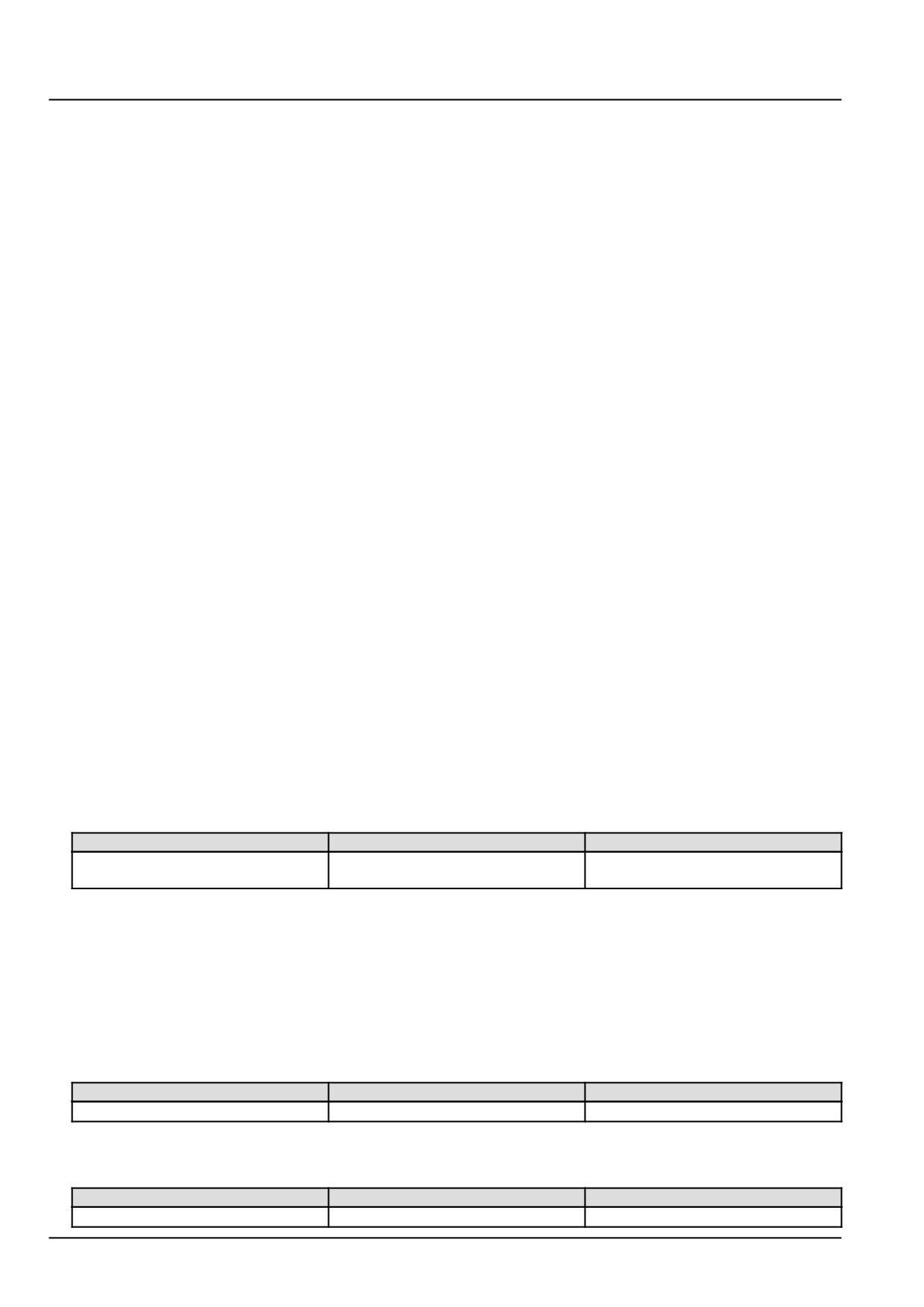
From
To
Value
X-9127 pin 2
Chassis ground
There should be no voltage.
With the key in the ON position, use a multimeter to perform the following voltage check on the vehicle harness
side :
From
To
Value
X-9127 pin 2
Chassis ground
There should be less than 5.5 V
140
Electrical systems - FAULT CODES
A. If the specified values are not measured, there is a short to battery in the PM catalytic converter inlet tempera-
ture sensor B-9127 wiring. Use the appropriate service manual, if necessary, to locate and repair the shorted
conductor.
B. If the specified values are measured, leave connector X-9127 disconnected and continue to Step 4.
4.
Check the PM catalytic converter inlet temperature sensor B-9127 vehicle harness (VE) wiring for an open circuit
condition.
Disconnect the vehicle harness from the ECU A-9000 at connector X-9102.
With the key in the OFF position, use a multimeter to perform the following continuity check on the vehicle harness
(VE) side :
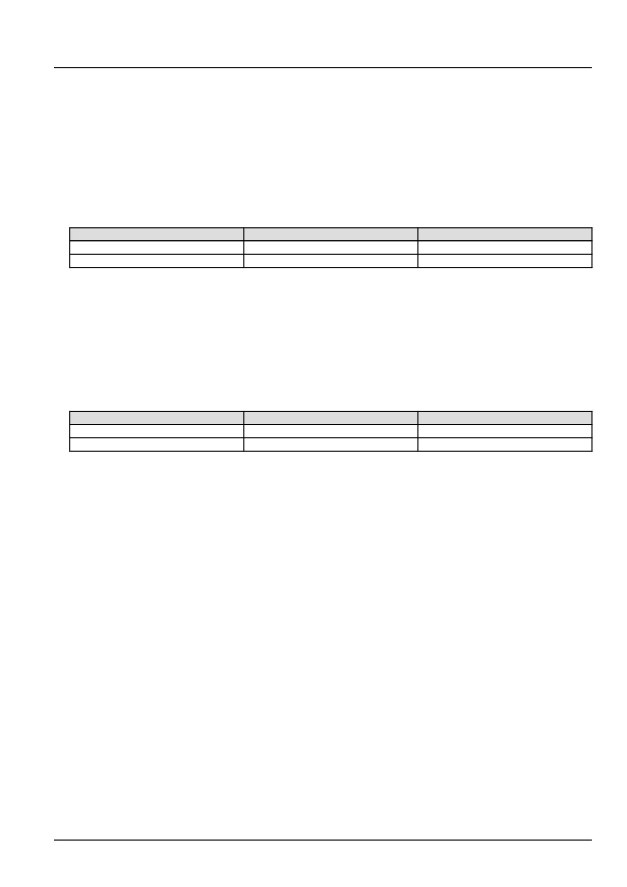
From
To
Value
X-9127 pin 2
X-9102 pin K83
There should be continuity.
X-9127 pin 1
X-9102 pin K84
There should be continuity.
A. If there is no continuity, there is an open circuit in the PM catalytic converter inlet temperature sensor B-9127
vehicle harness (VE) wiring. Use the appropriate service manual, if necessary, to locate and repair the broken
conductor.
B. If there is continuity, leave connectors X-9102 and X-9127 disconnected and continue to Step 5.
5.
Check the PM catalytic converter inlet temperature sensor B-9127 vehicle harness (VE) wiring for a short circuit
condition.
With the key in the OFF position, use a multimeter to perform the following continuity check on the vehicle harness
(VE) side :
From
To
Value
X-9102 pin K83
All pins in connector X-9102
There should be no continuity.
X-9102 pin K84
All pins in connector X-9102
There should be no continuity.
A. If there is continuity, there is a short circuit in the PM catalytic converter inlet temperature sensor B-9127 ve-
hicle harness (VE) wiring. Use the appropriate service manual, if necessary, to locate and repair the shorted
conductor.
B. If there is no continuity, check the ECU A-9000 for the appropriate software and re-flash, if necessary.
6.
Visually inspect the relevant harnesses and connectors for damage, bent or dislocated pins, corroded terminals,
or broken wires. Verify that the connectors are fully installed. Flex the harnesses involved to reveal intermittent
breaks or shorts in the wiring concerned. Operate the machine while you monitor the display.
A. If you find damage or the display indicates other than normal display readings, then repair the damage discov-
ered during the inspection or locate and repair the other than normal display condition and verify that the error
has been resolved.
B. If you do not find damage and the display indicates only normal readings, then erase the fault code and continue
operation.
Wiring harnesses - Electrical schematic sheet 02 - Engine Control Unit (ECU) power and after treatment
system (engine schematics) (55.100.DP-C.20.E.02)
141
Electrical systems - FAULT CODES
DTC 1F7-04-PMCat inlet temperature sensor voltage is lower than
expected
Control Module : ECU
Context:
The Engine Control Unit (ECU) A-9000 monitors the Particulate Matter (PM) catalytic converter inlet temperature sen-
sor B-9127. If the ECU A-9000 detects a voltage less than 459.40 mV in the PM catalytic converter inlet temperature
sensor B-9127 signal circuit, this fault will occur. If this fault is active, the last valid temperature value will be frozen
for a preliminary failure or set to a fixed replacement value of 99.96 °C (211.93 °F) if the failure is validated.
Cause:
The ECU A-9000 has detected a voltage less than 459.40 mV in the PM catalytic converter inlet temperature sensor
B-9127 signal circuit.
Possible failure modes:
1. Faulty PM catalytic converter inlet temperature sensor B-9127 wiring, short to ground condition.
2. Faulty PM catalytic converter inlet temperature sensor B-9127, internal failure.
3. Faulty ECU A-9000, software.
Solution:
1.
Verify fault is present and active.
Use the Electronic Service Tool (EST) to check the status of this fault.
A. If the fault is present and active, continue with Step 2.
B. If the fault is no longer present or in an inactive state, the fault may be intermittent and not currently active.
Continue with Step 5.
2.
Check the PM catalytic converter inlet temperature sensor B-9127 for an internal failure.
Disconnect the vehicle harness from the PM catalytic converter inlet temperature sensor B-9127 at connector
X-9127.
Use a multimeter to measure the resistance on the PM catalytic converter inlet temperature sensor B-9127 pins :
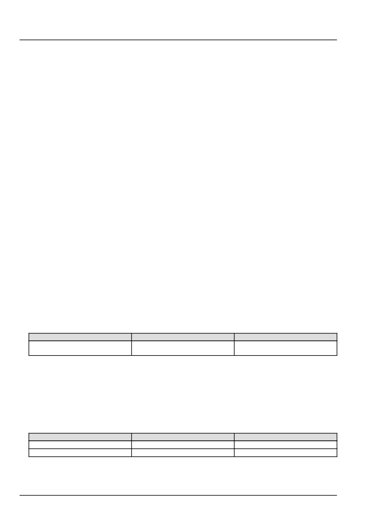
From
To
Value
X-9127 pin 1
X-9127 pin 2
There should be between 170.2 -
849.7 Ω.
A. If there is between 170.2 - 849.7 Ω, leave connector X-9127 pin 2 disconnected and continue to Step 3.
B. If there is between 170.2 - 849.7 Ω, the PM catalytic converter inlet temperature sensor B-9127 has failed.
Replace the PM catalytic converter inlet temperature sensor B-9127.
3.
Check the PM catalytic converter inlet temperature sensor B-9127 vehicle harness (VE) wiring for a short circuit
condition.
With the key in the OFF position, use a multimeter to perform the following continuity check on vehicle harness
(VE) side :
From
To
Value
X-9127 pin 2
X-9127 pin 1
There should be no continuity.
X-9127 pin 2
Chassis ground
There should be no continuity.
A. If there is continuity, there is a short circuit in the PM catalytic converter inlet temperature sensor B-9127 ve-
hicle harness (VE) wiring. Use the appropriate service manual, if necessary, to locate and repair the shorted
conductor.
142
Electrical systems - FAULT CODES
B. If there is no continuity, leave the connectors disconnected and continue to Step 4.
4. Check the PM catalytic converter inlet temperature sensor B-9127 vehicle harness (VE) wiring for a short circuit
condition.
Disconnect the vehicle harness from the ECU A-9000 at connector X-9102.
With the key in the OFF position, use a multimeter to perform the following continuity check at the vehicle harness
(VE) side of the connectors from :
From
To
Value
X-9102 pin K84
All pins in connector X-9102
There should be no continuity.
A. If there is continuity, there is a short circuit in the PM catalytic converter inlet temperature sensor B-9127 ve-
hicle harness (VE) wiring. Use the appropriate service manual, if necessary, to locate and repair the shorted
conductor.
B. If there is no continuity, check the ECU A-9000 for the appropriate software and re-flash, if necessary.
5. Visually inspect the relevant harnesses and connectors for damage, bent or dislocated pins, corroded terminals,
or broken wires. Verify that the connectors are fully installed. Flex the harnesses involved to reveal intermittent
breaks or shorts in the wiring concerned. Operate the machine while you monitor the display.
A. If you find damage or the display indicates other than normal display readings, then repair the damage discov-
ered during the inspection or locate and repair the other than normal display condition and verify that the error
has been resolved.
B. If you do not find damage and the display indicates only normal readings, then erase the fault code and continue
operation.
Wiring harnesses - Electrical schematic sheet 02 - Engine Control Unit (ECU) power and after treatment
system (engine schematics) (55.100.DP-C.20.E.02)
143
Electrical systems - FAULT CODES
DTC 225-03-Main relay stuck error
Control Module : ECU
Context:
The Engine Control Unit A-9000 controls the main relay K-9102. The main relay K-9102 is powered on by the ECU
A-9000 to achieve after-run. The main relay K-9102 is powered off once after-run is completed. If the ECU A-9000
determines that the main relay K-9102 is “stuck” or will not shut off as commanded, this fault will occur.
Cause:
The ECU A-9000 has determined that the main relay K-9102 will not shut off as commanded.
Possible failure modes:
1. Faulty main relay K-9102, wiring.
2. Faulty main relay K-9102, internal failure.
3. Faulty ECU A-9000, software.
Solution:
1.
Verify fault is present and active.
Use the Electronic Service Tool (EST) to check the status of this fault.
A. If the fault is present and active, continue with Step 2.
B. If the fault is no longer present or in an inactive state, the fault may be intermittent and not currently active.
Continue with Step 7.
2.
Check the main relay K-9102 coil for an internal failure.
Remove the main relay K-9102.
Use a multimeter to measure the resistance on the main relay K-9102 pins :
From
To
Value
X-9129 pin 85
X-9129 pin 86
There should be approximately 70 -
130 Ω.
A. If there is approximately 70 - 130 Ω, leave the main relay K-9102 disconnected and continue to Step 3.
B. If there is not approximately 70 - 130 Ω, the main relay K-9102 has failed. Replace the main relay K-9102.
3.
Check the main relay K-9102 low side driver wiring for a short to ground.
With the key in the OFF position, use a multimeter to perform the following continuity check for a short to ground
on the vehicle harness (VE) side :
From
To
Value
X-9129 pin 86
Chassis ground
There should be no continuity.
A. If there is continuity, there is a short circuit in the main relay K-9102 wiring in the vehicle harness (VE). Use the
appropriate service manual, if necessary, to locate and repair the shorted conductor.
B. If there is no continuity, leave the main relay K-9102 disconnected and continue to Step 4.
4.
Check the main relay K-9102 low side driver wiring for a short circuit.
Disconnect the vehicle harness (VE) from the ECU A-9000 at connector X-9102.
With the key in the OFF position, use a multimeter to perform the following continuity checks for a short circuit on
the vehicle harness (VE) side :
144
Electrical systems - FAULT CODES
From
To
Value
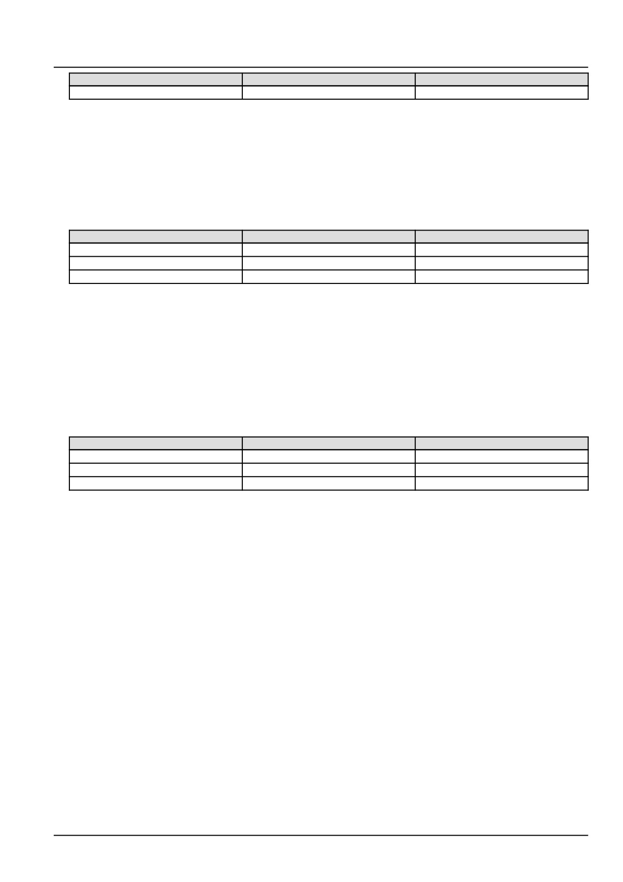
X-9102 pin K28
All pins in connector X-9102
There should be no continuity.
A. If there is continuity, there is a short circuit in the main relay K-9102 wiring in the vehicle harness (VE). Use the
appropriate service manual, if necessary, to locate and repair the shorted conductor.
B. If there is no continuity, leave the main relay K-9102 and connector X-9102 disconnected, then continue to
Step 5.
5.
Check the ECU A-9000 voltage supply wiring for a short to a voltage source.
With the key in the OFF position, use a multimeter to perform the following voltage checks for a short to a voltage
source on the vehicle harness (VE) side :
From
To
Value
X-9102 pin K01
Chassis ground
There should be no voltage.
X-9102 pin K03
Chassis ground
There should be no voltage.
X-9102 pin K05
Chassis ground
There should be no voltage.
A. If there is voltage, there is a short to a voltage source in the ECU A-9000 voltage supply wiring. Use the
appropriate service manual, if necessary, to locate and repair the shorted conductor.
B. If there is no voltage, leave the main relay K-9102 and connector X-9102 disconnected, then continue to Step
6.
6.
Check the ECU A-9000 voltage supply wiring for a short to a voltage source.
Re-connect the main relay K-9102.
With the key in the OFF position, use a multimeter to perform the following voltage checks for a short to a voltage
source on the vehicle harness (VE) side :
From
To
Value
X-9102 pin K01
Chassis ground
There should be no voltage.
X-9102 pin K03
Chassis ground
There should be no voltage.
X-9102 pin K05
Chassis ground
There should be no voltage.
A. If there is voltage, the main relay K-9102 has failed. Replace the main relay K-9102.
B. If there is no voltage, check the ECU A-9000 for the appropriate software and re-flash, if necessary.
7.
Visually inspect the relevant harnesses and connectors for damage, bent or dislocated pins, corroded terminals,
or broken wires. Verify that the connectors are fully installed. Flex the harnesses involved to reveal intermittent
breaks or shorts in the wiring concerned. Operate the machine while you monitor the display.
A. If you find damage or the display indicates other than normal display readings, then repair the damage discov-
ered during the inspection or locate and repair the other than normal display condition and verify that the error
has been resolved.
B. If you do not find damage and the display indicates only normal readings, then erase the fault code and continue
operation.
Wiring harnesses - Electrical schematic sheet 02 - Engine Control Unit (ECU) power and after treatment
system (engine schematics) (55.100.DP-C.20.E.02)
145
Electrical systems - FAULT CODES
DTC 225-03-Main relay stuck error
Control Module : ECU
Context:
The Engine Control Unit A-9000 controls the main relay K-9102. The main relay K-9102 is powered on by the ECU
A-9000 to achieve after-run. The main relay K-9102 is powered off once after-run is completed. If the ECU A-9000
determines that the main relay K-9102 has shut off before commanded, this fault will occur.
Cause:
The ECU A-9000 has determined that the main relay K-9102 has shut off before commanded to shut off.
Possible failure modes:
1. Faulty main relay K-9102, wiring.
2. Faulty main relay K-9102, internal failure.
3. Faulty ECU A-9000, software.
Solution:
1.
Verify fault is present and active.
Use the Electronic Service Tool (EST) to check the status of this fault.
A. If the fault is present and active, continue with Step 2.
B. If the fault is no longer present or in an inactive state, the fault may be intermittent and not currently active.
Continue with Step 9.
2.
Check the main relay K-9102 coil for an internal failure.
Remove the main relay K-9102.
Use a multimeter to measure the resistance on the main relay K-9102 pins :
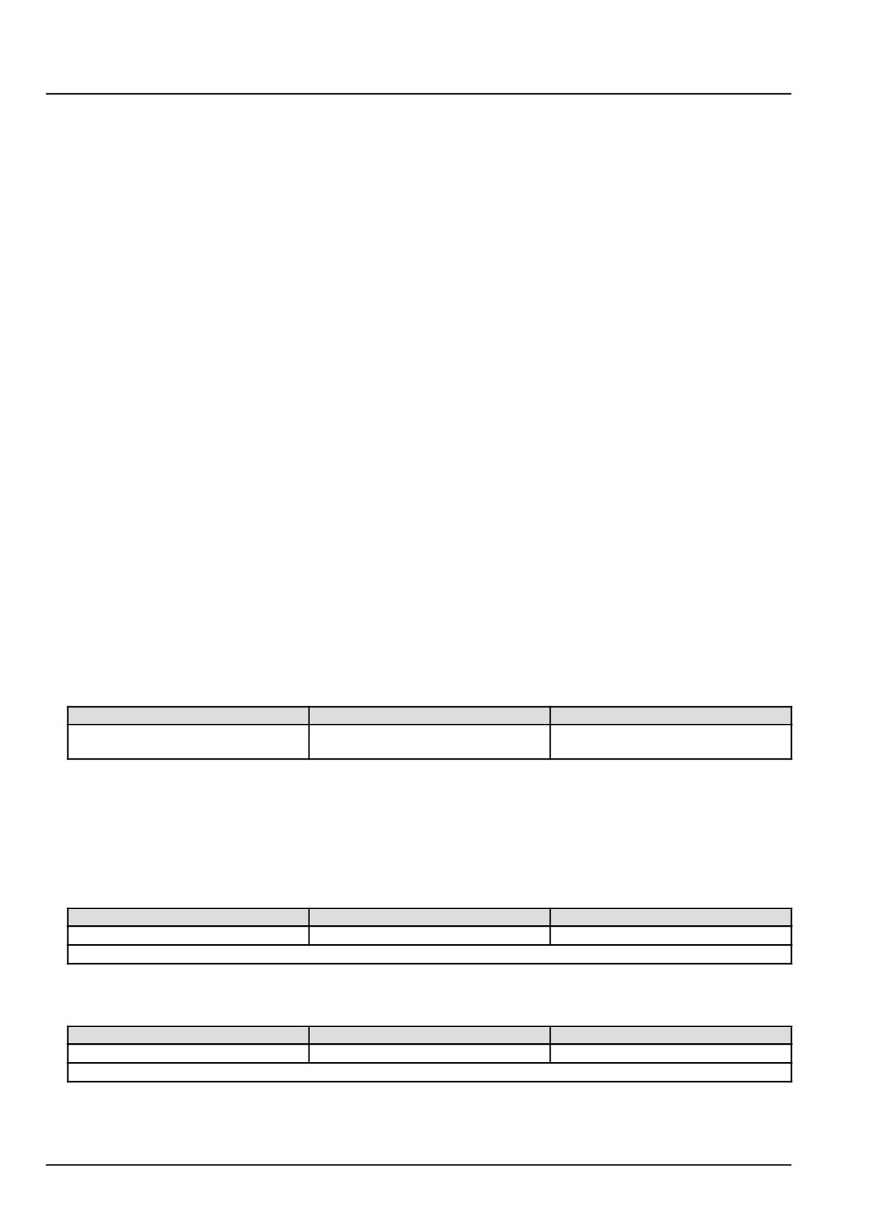
From
To
Value
X-9129 pin 85
X-9129 pin 86
There should be approximately 70 -
130 Ω.
A. If there is approximately 70 - 130 Ω, leave the main relay K-9102 disconnected and continue to Step 3.
B. If there is not approximately 70 - 130 Ω, the main relay K-9102 has failed. Replace the main relay K-9102.
3.
Check the main relay K-9102 vehicle harness (VE) wiring for a short to a voltage source.
With the key in the OFF position, use a multimeter to perform the following voltage check for a short to a voltage
source on the vehicle harness (VE) side :
From
To
Value
X-9129 pin 85
Chassis ground
There should be no voltage.
NOTE: Wiggle the harness during the check to promote an intermittent electrical connection.
With the key in the ON position, use a multimeter to perform the following voltage check for a short to a voltage
source on the vehicle harness (VE) side :
From
To
Value
X-9129 pin 85
Chassis ground
There should be no voltage.
NOTE: Wiggle the harness during the check to promote an intermittent electrical connection.
A. If there is voltage, there is a short to a voltage source in the main relay K-9102 wiring in the vehicle harness
(VE). Use the appropriate service manual, if necessary, to locate and repair the shorted conductor.
146
Electrical systems - FAULT CODES
B. If there is no voltage, leave the main relay K-9102 disconnected and continue to Step 4.
4.
Check the main relay K-9102 vehicle harness (VE) wiring for a short to ground.
With the key in the OFF position, use a multimeter to perform the following continuity check for a short to ground
on the vehicle harness (VE) side :
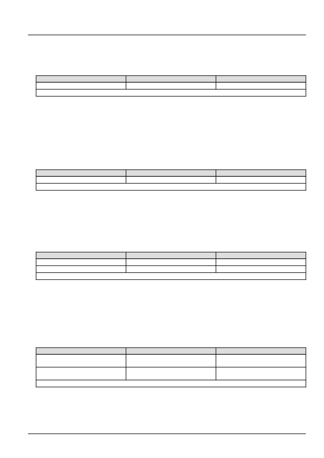
From
To
Value
X-9129 pin 85
Chassis ground
There should be no continuity.
NOTE: Wiggle the harness during the check to promote an intermittent electrical connection.
A. If there is continuity, there is a short to ground in the main relay K-9102 wiring in the vehicle harness (VE). Use
the appropriate service manual, if necessary, to locate and repair the broken or damaged conductor.
B. If there is no continuity, leave the main relay K-9102 disconnected and continue to Step 5.
5.
Check the main relay K-9102 vehicle harness (VE) wiring for an open circuit.
Disconnect the vehicle harness (VE) from the ECU A-9000 at connector X-9102.
With the key in the OFF position, use a multimeter to perform the following continuity check for an open circuit on
the vehicle harness (VE) side :
From
To
Value
X-9129 pin 85
X-9102 pin K28
There should be continuity.
NOTE: Wiggle the harness during the check to promote an intermittent electrical connection.
A. If there is no continuity, there is an open circuit in the main relay K-9102 wiring in the vehicle harness (VE).
Use the appropriate service manual, if necessary, to locate and repair the broken or damaged conductor.
B. If there is continuity, leave the main relay K-9102 and connector X-9102 disconnected, then continue to Step 6.
6.
Check the main relay K-9102 wiring for a short circuit condition.
With the key in the OFF position, use a multimeter to perform the following continuity checks for a short circuit on
the vehicle harness (VE) side :
From
To
Value
X-9129 pin 85
X-9129 pin 86
There should be no continuity.
X-9102 pin K28
All pins in connector X-9102
There should be no continuity.
NOTE: Wiggle the harness during the check to promote an intermittent electrical connection.
A. If there is continuity, there is a short circuit in the main relay K-9102 vehicle harness (VE) wiring. Use the
appropriate service manual, if necessary, to locate and repair the shorted conductor.
B. If there is no continuity, leave the main relay K-9102 and connector X-9102 disconnected, then continue to
Step 7.
7.
Check the main relay K-9102 load-side wiring.
With the key in the ON position, use a multimeter to perform the following voltage checks on the vehicle harness
(VE) side :
From
To
Value
X-9129 pin 86
Chassis ground
There should be approximately
12.0 V.
X-9129 pin 30
Chassis ground
There should be approximately
12.0 V.
NOTE: Wiggle the harness during the check to promote an intermittent electrical connection.
A. If there is not approximately 12.0 V, there is a failure in the main relay K-9102 load-side wiring. Use the appro-
priate service manual, if necessary, to locate and repair the shorted conductor.
B. If there is approximately 12.0 V, leave the main relay K-9102 and connector X-9102 disconnected, then con-
tinue to Step 8.
147
Electrical systems - FAULT CODES
8. Check the main relay K-9102 load-side wiring.
With the key in the OFF position, use a multimeter to perform the following continuity checks on the vehicle harness
(VE) side :
From
To
Value
X-9129 pin 87
X-9102 pin K01
There should be continuity.
X-9129 pin 87
X-9102 pin K03
There should be continuity.
X-9129 pin 87
X-9102 pin K05
There should be continuity.
NOTE: Wiggle the harness during the check to promote an intermittent electrical connection.
A. If there is no continuity, there is an open circuit in the main relay K-9102 load-side wiring or fuse. Use the
appropriate service manual, if necessary, to locate and repair the shorted conductor or open fuse.
B. If there is continuity, check the ECU A-9000 for the appropriate software and re-flash, if necessary.
9. Visually inspect the relevant harnesses and connectors for damage, bent or dislocated pins, corroded terminals,
or broken wires. Verify that the connectors are fully installed. Flex the harnesses involved to reveal intermittent
breaks or shorts in the wiring concerned. Operate the machine while you monitor the display.
A. If you find damage or the display indicates other than normal display readings, then repair the damage discov-
ered during the inspection or locate and repair the other than normal display condition and verify that the error
has been resolved.
B. If you do not find damage and the display indicates only normal readings, then erase the fault code and continue
operation.
Wiring harnesses - Electrical schematic sheet 02 - Engine Control Unit (ECU) power and after treatment
system (engine schematics) (55.100.DP-C.20.E.02)
148
Electrical systems - FAULT CODES
DTC 226-03-Battery voltage is higher than expected
Control Module : ECU
Context:
The Engine Control Unit (ECU) A-9000 monitors the battery voltage. If the ECU A-9000 detects a voltage higher than
expected, this fault will occur.
Cause:
The ECU A-9000 has detected a battery voltage of greater than 28.8 V.
Possible failure modes:
1. Faulty alternator, failed regulator.
2. Faulty ECU A-9000, software.
Solution:
1.
Verify fault is present and active.
Use the Electronic Service Tool (EST) to check the status of this fault.
A. If the fault is present and active, continue with Step 2.
B. If the fault is no longer present or in an inactive state, the fault may be intermittent and not currently active.
Continue with Step 3.
2.
Start the engine and raise the Revolutions Per Minute (RPM) to approximately 1500 RPM for 1.00 min. Lower the
RPM to idle speed and check the battery voltage with the engine running.
With the engine running, use a multimeter to perform the following voltage check on the battery posts :
From
To
Value
Battery +
Battery -
14.8 - 16.2 V
A. If the voltage is high, out of range (normal engine running operating range is approximately 14.8 - 16.2 V, the
alternator has failed. Replace the alternator.
B. If the voltage is within range (normal engine running operating range is approximately 14.8 - 16.2 V, check the
ECU A-9000 for the appropriate software and re-flash, if necessary.
3.
Visually inspect the relevant harnesses and connectors for damage, bent or dislocated pins, corroded terminals,
or broken wires. Verify that the connectors are fully installed. Flex the harnesses involved to reveal intermittent
breaks or shorts in the wiring concerned. Operate the machine while you monitor the display.
A. If you find damage or the display indicates other than normal display readings, then repair the damage discov-
ered during the inspection or locate and repair the other than normal display condition and verify that the error
has been resolved.
B. If you do not find damage and the display indicates only normal readings, then erase the fault code and continue
operation.
149
Electrical systems - FAULT CODES
DTC 226-04-Battery voltage is lower than expected
Control Module : ECU
Context:
The Engine Control Unit (ECU) A-9000 monitors the battery voltage. If the ECU A-9000 detects a voltage lower than
expected, this fault will occur.
Cause:
The ECU A-9000 has detected a battery voltage of less than 8.3 V.
Possible failure modes:
1. Faulty battery.
2. Faulty alternator, failed regulator.
3. Engine started in extreme cold conditions.
4. Faulty ECU A-9000, software.
Solution:
1.
Verify fault is present and active.
Use the Electronic Service Tool (EST) to check the status of this fault.
A. If the fault is present and active, continue with Step 2.
B. If the fault is no longer present or in an inactive state, the fault may be intermittent and not currently active.
Continue with Step 6.
2.
Charge the battery and perform a battery load test.
A. If the pass battery does not pass the load test, replace the battery.
B. If the battery passes the load test, continue to Step 3.
3.
Start the engine and raise the Revolutions Per Minute (RPM) to about 1500 RPM for 1.00 min. Lower the RPM to
idle speed and check the battery voltage with the engine running.
With the engine running, use a multimeter to perform the following voltage check on the battery posts :
From
To
Value
Battery +
Battery -
14.8 - 16.2 V
A. If the voltage is low, out of range (normal engine running operating range is approximately 14.8 - 16.2 V, the
alternator has failed. Replace the alternator.
B. If the voltage is within range (normal engine running operating range is approximately 14.8 - 16.2 V, continue
to Step 4.
4.
Check the ECU A-9000 voltage supply wiring.
Disconnect the vehicle harness (VE) from the ECU A-9000 at connector X-9102.
Place a jumper wire between X-9102 pin K28 and chassis ground. This will energize the main relay K-9102.
With the key in the ON position, use a multimeter to perform the following voltage check on the vehicle harness
(VE) side :
From
To
Value
X-9102 pin K01
Chassis ground
There should be approximately 12 V.
X-9102 pin K03
Chassis ground
There should be approximately 12 V.
X-9102 pin K05
Chassis ground
There should be approximately 12 V.
150
Electrical systems - FAULT CODES
A. If there is less than approximately 12 V, continue to Step 5.
B. If there is approximately 12 V, check the ECU A-9000 for the appropriate software and re-flash, if necessary.
5. Check the ECU A-9000 voltage supply wiring for a short circuit to ground.
With the key in the ON position, use a multimeter to perform the following voltage check on the vehicle harness
(VE) side :
From
To
Value
X-9102 pin K01
Chassis ground
There should be no continuity.
X-9102 pin K03
Chassis ground
There should be no continuity.
X-9102 pin K05
Chassis ground
There should be no continuity.
A. If there is continuity, there is a short circuit to ground condition in the ECU A-9000 voltage supply wiring. Use
the appropriate service manual to locate and repair the shorted conductor.
B. If there is no continuity, check the ECU A-9000 for the appropriate software and re-flash, if necessary.
6. Visually inspect the relevant harnesses and connectors for damage, bent or dislocated pins, corroded terminals,
or broken wires. Verify that the connectors are fully installed. Flex the harnesses involved to reveal intermittent
breaks or shorts in the wiring concerned. Operate the machine while you monitor the display.
A. If you find damage or the display indicates other than normal display readings, then repair the damage discov-
ered during the inspection or locate and repair the other than normal display condition and verify that the error
has been resolved.
B. If you do not find damage and the display indicates only normal readings, then erase the fault code and continue
operation.
Wiring harnesses - Electrical schematic sheet 02 - Engine Control Unit (ECU) power and after treatment
system (engine schematics) (55.100.DP-C.20.E.02)
151
Electrical systems - FAULT CODES
DTC 236-03-Rail pressure sensor value is above maximum offset
Control Module : ECU
NOTE: If the rail pressure sensor B-9004 is replaced, it is necessary to perform the Replacement of the Rail Pressure
sensor - Reset ECU Data with the Electronic Service Tool (EST) before you return the machine to service. See
Common rail pressure sensor - Configure - Reset ECU data (Rail pressure sensor) (55.010), if necessary.
152
Electrical systems - FAULT CODES
DTC 236-03-Rail pressure sensor value is above maximum offset
Control Module : ECU
NOTE: If the Pressure Relief Valve (PRV) is replaced, it is necessary to perform the Replacement of the Rail Pressure
Relief Valve (PRV) - Reset ECU Data with the Electronic Service Tool (EST) before you return the machine to service.
See Common rail Relief valve - Configure - Reset ECU data (10.218), if necessary.
Context:
The Engine Control Unit (ECU) A-9000 monitors the fuel Pressure Relief Valve (PRV). If the ECU A-9000 determines
that the PRV has been open for too long, this fault will occur. The PRV opening duration is monitored by the ECU
A-9000 and stored in the EEPROM during after run. This fault is for informational purposes only. If this fault is active,
other fuel system faults may be active that caused this fault to occur. Diagnose any faults that may have caused
this one to occur first, and then return to this fault, DTC 237-Max - Open time of PRV for wear out monitoring had
exceeded maximum value. For more information regarding fuel system troubleshooting, see Fuel injection system
- Troubleshooting (10.218).
Cause:
The ECU A-9000 has determined that the PRV has reached its maximum allowed open time.
Possible failure modes:
1. Faulty PRV, stuck open or worn.
2. Faulty fuel back-flow, clogged or damaged.
3. Faulty fuel metering unit Y-9000, internal failure.
4. Faulty rail pressure sensor B-9004, internal failure.
5. Faulty ECU A-9000, software.
153
Electrical systems - FAULT CODES
DTC 236-04-Rail pressure sensor value is below minimum offset
Control Module : ECU
NOTE: If the rail pressure sensor B-9004 is replaced, it is necessary to perform the Replacement of the Rail Pressure
sensor - Reset ECU Data with the Electronic Service Tool (EST) before you return the machine to service. See
Common rail pressure sensor - Configure - Reset ECU data (Rail pressure sensor) (55.010), if necessary.
154
Electrical systems - FAULT CODES
DTC 237-04-Fuel pressure relief valve is forced to open, perform
pressure shock
Control Module : ECU
Context:
This fault is intended for information purposes only. Other active faults may have caused this fault to occur. The
Engine Control Unit (ECU) A-9000, if necessary, will set the engine into limp home mode. This process is achieved
in two steps by the ECU A-9000, a pressure increase and a pressure shock. The ECU A-9000 will execute step two
by a fuel pressure shock. This is achieved by setting injection quantity to zero. If this fault is active, the ECU A-9000
has performed step two for achieving limp home mode, a fuel pressure shock.
Cause:
The ECU A-9000 has performed a fuel pressure shock to achieve limp home mode.
155
Electrical systems - FAULT CODES
DTC 237-04-Fuel pressure relief valve is forced to open, perform
pressure shock
Control Module : ECU
Context:
This fault is intended for information purposes only. Other active faults may have caused this fault to occur. The
Engine Control Unit (ECU) A-9000, if necessary, will set the engine into limp home mode. This process is achieved
in two steps by the ECU A-9000, a pressure increase and a pressure shock. The ECU A-9000 will execute step two
by a fuel pressure shock. This is achieved by setting injection quantity to zero. If this fault is active, the ECU A-9000
has performed step two for achieving limp home mode, a fuel pressure shock.
Cause:
The ECU A-9000 has performed a fuel pressure shock to achieve limp home mode.
156
Electrical systems - FAULT CODES
DTC 237-12-Quantity balance check if a successful PRV opening
is ensured
Control Module : ECU
Context:
This fault is intended for information purposes only. Other active faults may have caused this fault to occur. The
Engine Control Unit (ECU) A-9000, monitors the fuel Pressure Relief Valve (PRV). To determine mechanical wear-out
of the PRV, the ECU A-9000 will perform a fuel pressure increase and pressure shock, thus opening the PRV. Both
steps are recorded in the ECU A-9000 failure memory.
157
Electrical systems - FAULT CODES
DTC 237-12-Quantity balance check if a successful PRV opening
is ensured
Control Module : ECU
Context:
This fault is intended for information purposes only. Other active faults may have caused this fault to occur. The
Engine Control Unit (ECU) A-9000, monitors the fuel Pressure Relief Valve (PRV). To determine mechanical wear-out
of the PRV, the ECU A-9000 will perform a fuel pressure increase and pressure shock, thus opening the PRV. Both
steps are recorded in the ECU A-9000 failure memory.
158
Electrical systems - FAULT CODES
DTC 238-03-Oil pressure switch active with engine off
Control Module : ECU
Context:
The Engine Control Unit (ECU) A-9000 monitors the oil pressure switch S-9016 for proper operation. The oil pressure
switch S-9016 changes from its off to on state between 0.6 - 0.9 bar (8.7 - 13.0 psi). If the oil pressure switch S-9016
does not return to its off state, once the engine is switched OFF, this fault will occur.
Cause:
The ECU A-9000 has sensed that the oil pressure switch S-9016 did not return to its off state.
Possible failure modes:
1. Faulty oil pressure switch S-9016, failed internally.
2. Faulty oil pressure switch S-9016 circuit wiring, open circuit.
3. Faulty ECU A-9000, software.
Solution:
1.
Verify that the fault is present and active.
Use the Electronic Service Tool (EST) to check the status of this fault.
A. If the fault is present and active, continue with Step 2.
B. If the fault is no longer present or in an inactive state, the fault may be intermittent and not currently active.
Continue with Step 4.
2.
Check the condition of the oil pressure switch S-9016.
Disconnect the engine harness (EN) from the oil pressure switch S-9016 at connector X-9016.
Use a multimeter to check for continuity on the component side :
From
To
Value
X-9016 pin 1
chassis ground
There should be continuity.
A. If there is continuity, leave connector X-9016 disconnected and continue with Step 3.
B. If there is no continuity, the oil pressure switch S-9016 has failed internally, replace the oil pressure switch
S-9016.
3.
Check the oil pressure switch S-9016 circuit for an open circuit condition.
Carefully disconnect the engine harness (EN) from the ECU A-9000 at connector X-9001.
Place a jumper wire between connector X-9001 pin A06 and chassis ground.
Use a multimeter to check for continuity on the engine harness (EN) side :
From
To
Value
X-9016 pin 1
chassis ground
There should be continuity.
A. If there is no continuity, there is an open circuit in the oil pressure switch S-9016 circuit. Locate and repair the
broken conductor.
B. If there is continuity, check the ECU A-9000 for the appropriate software and re-flash, if necessary.
4.
Visually inspect the relevant harnesses and connectors for damage, bent or dislocated pins, corroded terminals,
or broken wires.
Verify that the connectors are fully installed.
Flex the harnesses involved to reveal intermittent breaks or shorts in the wiring concerned.
159
Electrical systems - FAULT CODES
Operate the machine while you monitor the display.
A. If you find damage or the display indicates other than normal display readings, then repair the damage discov-
ered during the inspection or locate and repair the other than normal display condition and verify that the error
has been resolved.
B. If you do not find damage and the display indicates only normal readings, then erase the fault code and continue
operation.
Wiring harnesses - Electrical schematic sheet 03 - Engine sensors and fuel injection (engine schematics)
(55.100.DP-C.20.E.03)
160
Electrical systems - FAULT CODES
DTC 238-04-Low oil pressure
Control Module : ECU
Context:
The Engine Control Unit (ECU) A-9000 monitors the oil pressure switch S-9016 for proper operation. The oil pressure
switch S-9016 changes from its off to on state between 0.6 - 0.9 bar (8.7 - 13.0 psi). If the oil pressure switch S-9016
does actuate once the engine has been running for 6.0 s at greater than 500.0 RPM, this fault will occur.
Cause:
The ECU A-9000 has determined that the oil pressure switch S-9016 did not actuate.
Possible failure modes:
1. Faulty oil level, too low.
2. Faulty oil pressure switch S-9016, failed internally.
3. Faulty oil pressure switch S-9016 circuit wiring, shorted to chassis ground.
4. Faulty oil pressure, too low or blockage.
5. Faulty ECU A-9000, hardware or software.
Solution:
1.
Verify that the fault is present and active.
Use the Electronic Service Tool (EST) to check the status of this fault.
A. If the fault is present and active, continue with Step 2.
B. If the fault is no longer present or in an inactive state, the fault may be intermittent and not currently active.
Continue with Step 7.
2.
Check oil level.
Use the appropriate operator or service manual, if necessary, to determine if the lubrication system has the ap-
propriate amount of oil.
There should be at least the minimum acceptable level of oil.
A. If there is at least the minimum acceptable level of oil, continue with Step 3.
B. If there less than the minimum acceptable level of oil, use the appropriate operator or service manual, if nec-
essary, to determine the type and quantity of oil required to re-fill the oil system.
3.
Check the condition of the oil pressure switch S-9016.
Disconnect the engine harness (EN) from the oil pressure switch S-9016 at connector X-9016.
With the engine not running, use a multimeter to check for continuity on the component side :
From
To
Result
X-9016 pin 1
chassis ground
There should be continuity.
Start the engine and allow it to run at greater than 500 RPM for at least 6.0 s.
While the engine is running at greater than 500 RPM, use a multimeter to check for continuity on the component
side :
From
To
Result
X-9016 pin 1
chassis ground
There should be no continuity.
A. If the specified values are measured, leave connector X-9016 disconnected and continue with Step 4.
161
Electrical systems - FAULT CODES
B. If the oil pressure switch S-9016 did not change state, leave connector X-9016 disconnected and continue with
Step 6.
4.
Check the oil pressure switch S-9016 circuit for a short to ground condition.
With the key switch in the OFF position, use a multimeter to check for continuity on the engine harness (EN) side :
From
To
Result
X-9016 pin 1
chassis ground
There should be no continuity.
A. If there is continuity, leave connector X-9016 disconnected and continue with Step 5.
B. If there is no continuity, check the ECU A-9000 for the appropriate software and re-flash, if necessary.
5.
Locate the short to ground condition.
Carefully disconnect the engine harness (EN) from the ECU A-9000 at connector X-9001.
With the key in the OFF position, use a multimeter to check for continuity on the engine harness (EN) side :
From
To
Result
X-9001 pin A06
chassis ground
There should be no continuity.
A. If there is continuity, the short to chassis ground condition is in the engine harness (EN) between connector
X-9001 pin A06 and connector X-9016 pin 1. Use the appropriate service manual, if necessary, to locate and
repair the grounded conductor.
B. If there is no continuity, the ECU A-9000 has failed internally, replace the ECU A-9000.
6.
Check lubrication system for blockage.
See Engine lubrication system - Test (10.304), if necessary, to determine if the lubrication system has the ap-
propriate amount of oil pressure.
Between 0.6 - 0.9 bar (8.7 - 13.0 psi) is required to actuate the oil pressure switch S-9016.
There should be at least the minimum acceptable level of oil pressure.
A. If there is adequate oil pressure, the oil pressure switch S-9016 has failed internally replace the switch.
B. If there less than the minimum acceptable level of oil pressure, use the appropriate service manual, if neces-
sary, to locate and restore oil pressure to the lubrication system.
7.
Visually inspect the relevant harnesses and connectors for damage, bent or dislocated pins, corroded terminals,
or broken wires.
Verify that the connectors are fully installed.
Flex the harnesses involved to reveal intermittent breaks or shorts in the wiring concerned.
Operate the machine while you monitor the display.
A. If you find damage or the display indicates other than normal display readings, then repair the damage discov-
ered during the inspection or locate and repair the other than normal display condition and verify that the error
has been resolved.
B. If you do not find damage and the display indicates only normal readings, then erase the fault code and continue
operation.
Wiring harnesses - Electrical schematic sheet 03 - Engine sensors and fuel injection (engine schematics)
(55.100.DP-C.20.E.03)
162
Electrical systems - FAULT CODES
DTC 256-03-Engine speed limitation via fuel injection cut off is
active
Control Module : ECU
Context:
The Engine Control Unit (ECU) A-9000 will perform an injection cut-off to limit the engine speed to a controllable range,
if needed. Implausible signals from certain parameters such as accelerator pedal signal, fuel injection parameters
or engine speed can cause an injection cut-off. If torque or injection quantity are not plausible and engine speed is
greater than 1200 RPM, this fault will occur. Other active faults may have caused this fault to occur.
Solution:
1. Check the ECU A-9000 for the appropriate software and re-flash, if necessary.
A. If the fault has been resolved, return the machine to service.
B. If the fault has not been resolved, escalate an ASIST concern.
163
Electrical systems - FAULT CODES
DTC 259-03-Fuel metering unit is shorted to battery voltage at the
low side
Control Module : ECU
Context:
The Engine Control Unit (ECU) monitors the fuel metering unit Y-9000 signal circuit. If the ECU A-9000 detects a
short to a voltage source in the fuel metering unit Y-9000 low side driver circuit, this fault will occur.
Cause:
There is a short to a voltage source in the fuel metering unit Y-9000 low side driver circuit.
Possible failure modes:
1. Faulty fuel metering unit Y-9000 wiring, short to a voltage source.
2. Faulty fuel metering unit Y-9000, internal failure.
3. Faulty ECU A-9000, software.
Solution:
1.
Verify fault is present and active.
Use the Electronic Service Tool (EST) to check the status of this fault.
A. If the fault is present and active, continue with Step 2.
B. If the fault is no longer present or in an inactive state, the fault may be intermittent and not currently active.
Continue with Step 5.
2.
Test the fuel metering unit Y-9000 internal resistance.
Disconnect the engine harness (EN) from the fuel metering unit Y-9000 at connector X-9007.
Use a multimeter to measure the resistance on the fuel metering unit Y-9000 pins :
From
To
Value
X-9007 pin 1
X-9007 pin 2
There should be between 2.6 - 3.2 Ω
at approximately 20.0 °C (68.0 °F).
A. If there is between 2.6 - 3.2 Ω, leave connector X-9007 disconnected and continue to Step 3.
B. If there is not between 2.6 - 3.2 Ω, the fuel metering unit Y-9000 has failed. Replace the fuel metering unit
Y-9000.
3.
Check the fuel metering unit Y-9000 low side driver wiring for a short to battery condition.
With the key in the OFF position, use a multimeter to perform the following voltage check on the engine harness
(EN) side :
From
To
Value
X-9007 pin 1
Chassis ground
There should be no voltage.
With the key in the ON position, use a multimeter to perform the following voltage check on the engine harness
(EN) side :
From
To
Value
X-9007 pin 1
Chassis ground
There should be no voltage.
A. If there is voltage, there is a short circuit to battery or switched battery in the fuel metering unit Y-9000 low
side driver circuit wiring. Use the appropriate service manual, if necessary, to locate and repair the shorted
conductor.
164